○ ○○○○○○○○○○○○○○○○○○○○○○○○○○○○○○○○○○○○○○○○○○○○○○○○○○○○○○○○○○○○○○○○○○○○○○○○○○○○
Model 75700
Coolant Exchanger
Operating Manual
Before using the coolant exchanger, read, understand, and follow the safety precautions and operating
instructions outlined in this manual. This equipment must be operated by qualified personnel – the operator must be
familiar with vehicle cooling systems, coolants, and the dangers they present.
– If the operator cannot read English, operating instructions and safety precautions must be read and discussed in the
operator's native language.
– Si el operador no puede leer inglés, las instrucciones de operación y las precauciones de seguridad deberán leerse y
comentarse en el idioma nativo del operador.
– Si l'utilisateur ne peut lire l'anglais, les instructions et les consignes de sécurité doivent lui être expliquées dans sa langue
maternelle.
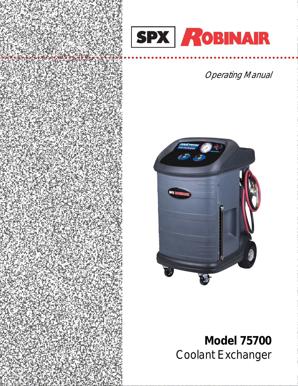
Do not drink antifreeze or solution. Avoid inhaling mist or hot vapors. (Ethylene glycol base.) If swallowed, drink
two glasses of water; induce vomiting; and call a physician. If inhaled, move to fresh air and call a physician. Use the unit
in locations with mechanical ventilation that provides at least four air changes per hour. If accidental system discharge
occurs, ventilate the work area before resuming work.
Do not store ethylene glycol based solutions in open or unlabeled containers. Ethylene glycol causes birth defects
in laboratory animals; solution may taste pleasant to animals, but is poisonous to them.
Contact with antifreeze/coolant may cause injury. Hot antifreeze/coolant can burn skin and injure eyes. Wear
protective equipment, including safety goggles and gloves, when operating this equipment. If contact with eyes occurs,
call a physician immediately, and flush eyes with cold water for 30 minutes. If contact with skin occurs, thoroughly wash
area with soap and water.
Vehicle cooling systems which are hot, are under pressure — opening a hot system, except as described in this
manual, can cause an uncontrolled release of engine coolant. Do not open the radiator cap, and do not remove hoses
from a hot system except as directed in this manual.
Do not pressurize the vehicle cooling system above its pressure rating. Doing so may result in cooling system failure
and the release of engine coolant.
Never run a vehicle engine without adequate ventilation. Breathing vehicle emissions can cause sickness, injury, or
death.
Working in the vicinity of a lead-acid or other automotive battery is dangerous. Wear eye protection. NEVER smoke,
or allow a spark or flame in the vicinity of a battery. Batteries generate explosive gases during normal battery operation.
This equipment is not designed for any other purposes than testing cooling systems and exchanging used antifreeze/
coolant with new or recycled product.
The operator is responsible for complying with any and all applicable laws and regulations governing the use of this type
of equipment, as well as disposal of used antifreeze/coolant and used equipment and components.
Model 75700
Coolant Exchanger
SAFETY DEFINITIONS: Follow all WARNING, CAUTION, IMPORTANT, and NOTE messages in this manual. These messages are
defined as follows: WARNING means you may risk death or serious personal injury; CAUTION means you may risk personal injury,
property damage, or serious unit damage; IMPORTANT means you may risk unit damage; and NOTEs provide clarity and helpful
tips. These safety messages cover situations ROBINAIR is aware of. ROBINAIR cannot know, evaluate, and advise you regarding all
possible hazards. You must make sure all conditions and procedures do not jeopardize your personal safety.
DISCLAIMER: All information, illustrations, and specifications contained in this manual are based on the latest information available
at the time of publication. The right is reserved to make changes at any time without obligation to notify any person or organization of
such revisions or changes. Further, ROBINAIR shall not be liable for errors contained herein or for incidental or consequential damages
(including lost profits) in connection with the furnishing, performance, or use of this material. If necessary, obtain additional health and
safety information from the appropriate government agencies, and the vehicle and coolant manufacturers.
Warning

1
Cool Tech 75700 CoolXchange
Table of Contents
Introduction . . . . . . . . . . . . . . . . . . . . . . . . . . . . . . . . . . . . . . . . . . . . . . . . . . 2
Technical Specifications . . . . . . . . . . . . . . . . . . . . . . . . . . . . . . . . . . . . 2
Glossary . . . . . . . . . . . . . . . . . . . . . . . . . . . . . . . . . . . . . . . . . . . . . . . . 2
Setup . . . . . . . . . . . . . . . . . . . . . . . . . . . . . . . . . . . . . . . . . . . . . . . . . . . . . . . 3
Attach Hoses . . . . . . . . . . . . . . . . . . . . . . . . . . . . . . . . . . . . . . . . . . . . 3
Assemble Supply Tanks . . . . . . . . . . . . . . . . . . . . . . . . . . . . . . . . . . . . 3
Relieve Cooling System Pressure . . . . . . . . . . . . . . . . . . . . . . . . . . . . . . . . . . 4
System Inspection . . . . . . . . . . . . . . . . . . . . . . . . . . . . . . . . . . . . . . . . 4
Relieve Pressure on a Hot System that has a Radiator Cap . . . . . . . . . 4
Lower the Coolant Level . . . . . . . . . . . . . . . . . . . . . . . . . . . . . . . . . . . . . . . . 5
Vehicle Connections . . . . . . . . . . . . . . . . . . . . . . . . . . . . . . . . . . . . . . . . . . . . 6
Pressure Test . . . . . . . . . . . . . . . . . . . . . . . . . . . . . . . . . . . . . . . . . . . . . . . . . . 7
Exchange Process . . . . . . . . . . . . . . . . . . . . . . . . . . . . . . . . . . . . . . . . . . . . . . 8
Complete the Exchange Process . . . . . . . . . . . . . . . . . . . . . . . . . . . . . 8
Maintenance . . . . . . . . . . . . . . . . . . . . . . . . . . . . . . . . . . . . . . . . . . . . . . . . . . 9
Changing Supply Tanks . . . . . . . . . . . . . . . . . . . . . . . . . . . . . . . . . . . . 9
Emptying the Waste Tank . . . . . . . . . . . . . . . . . . . . . . . . . . . . . . . . . . . 9
Cleaning the Filter . . . . . . . . . . . . . . . . . . . . . . . . . . . . . . . . . . . . . . . 10
Troubleshooting . . . . . . . . . . . . . . . . . . . . . . . . . . . . . . . . . . . . . . . . . . . . . . 11
Flow Chart . . . . . . . . . . . . . . . . . . . . . . . . . . . . . . . . . . . . . . . . . . . . . . . . . . 13
Accessories . . . . . . . . . . . . . . . . . . . . . . . . . . . . . . . . . . . . . . . . . . . . . . . . . . 14
Replacement Parts List . . . . . . . . . . . . . . . . . . . . . . . . . . . . . . . . . . . . . . . . . 16
Safety Precautions . . . . . . . . . . . . . . . . . . . . . . . . . . . . . . . Inside Front Cover
Warranty Statement . . . . . . . . . . . . . . . . . . . . . . . . . . . . . . Inside Back Cover
2
© 2003 SPX Corporation
Introduction
The 75700 COOLXCHANGE offers everything you need to quickly remove and replace coolant in a vehicle:
drain and fill, and pressure test for leaks. Two external, new coolant supply tanks allow on-board storage of
two different coolant types.
No electricity is needed—shop air powers the unit. No hoses to cut. No additional ventilation is required—the
service procedure is performed with the engine off. The coolant transfer process is “hands off”—simply make
the correct connections and watch it happen. A typical exchange procedure may take only 10 minutes!
Technical Specifications
Power Supply : 80–120 psi shop air
Internal Tank : 15-gallon capacity waste tank
External Tanks : Two 7-gallon capacity supply tanks
Dimensions : 47" H x 26" W x 33" D
(119 cm x 66 cm x 84 cm)
Glossary
Antifreeze : Substance used to lower the freezing
point of another liquid; has not yet
been mixed with water.
Coolant : A mixture of antifreeze and water.
System : The cooling system of the vehicle
being serviced.
Unit : The 75700 COOLXCHANGE.
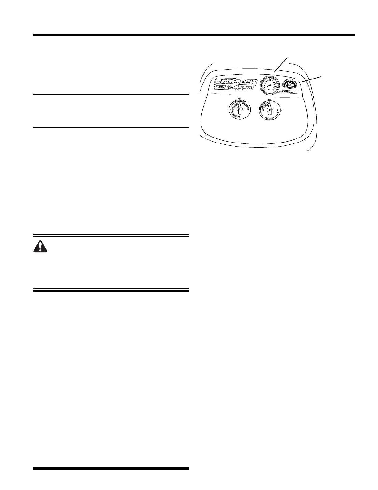
IMPORTANT : For
correct operation of
the 75700 unit, adjust
Valve 1 and Valve 2
in the sequence
specified in these
instructions.
ll
ll
l
ll
ll
l
ll
ll
l
ll
ll
l
ll
ll
l
ll
ll
l
ll
ll
l
ll
ll
l
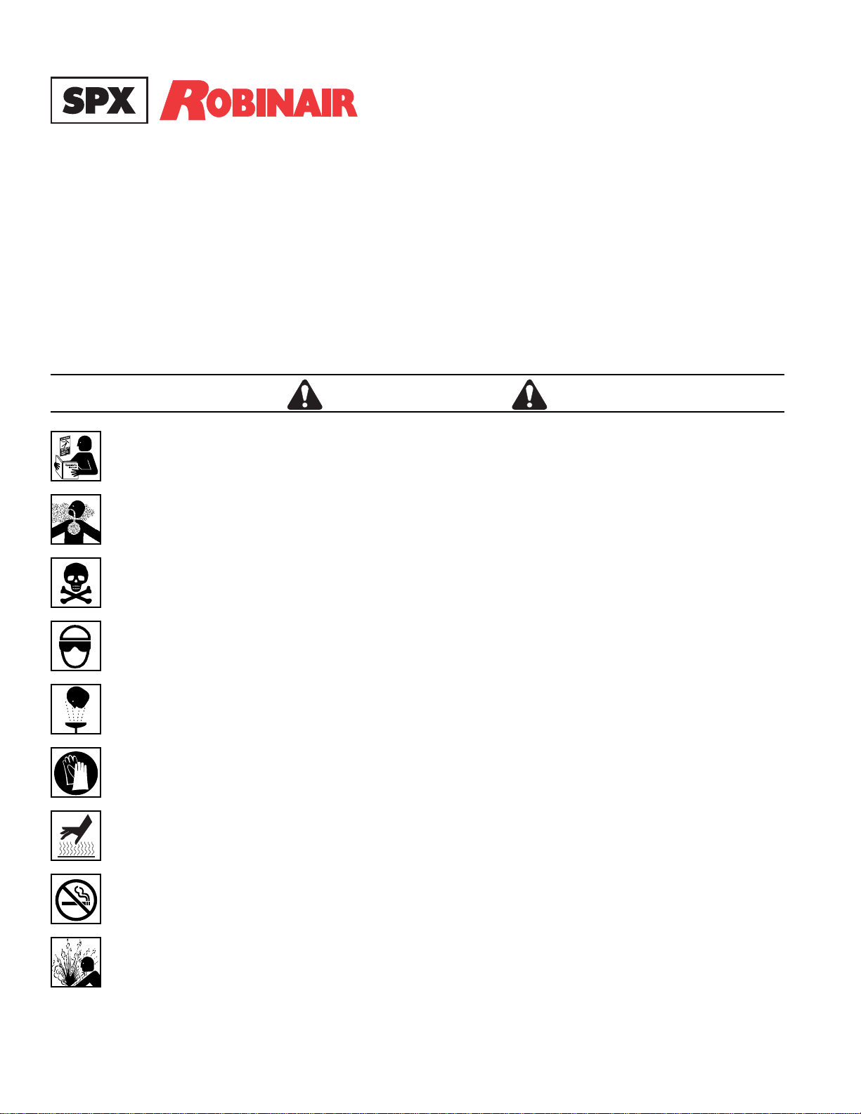
Valve 1
Valve 2
ll
ll
l
ll
ll
l
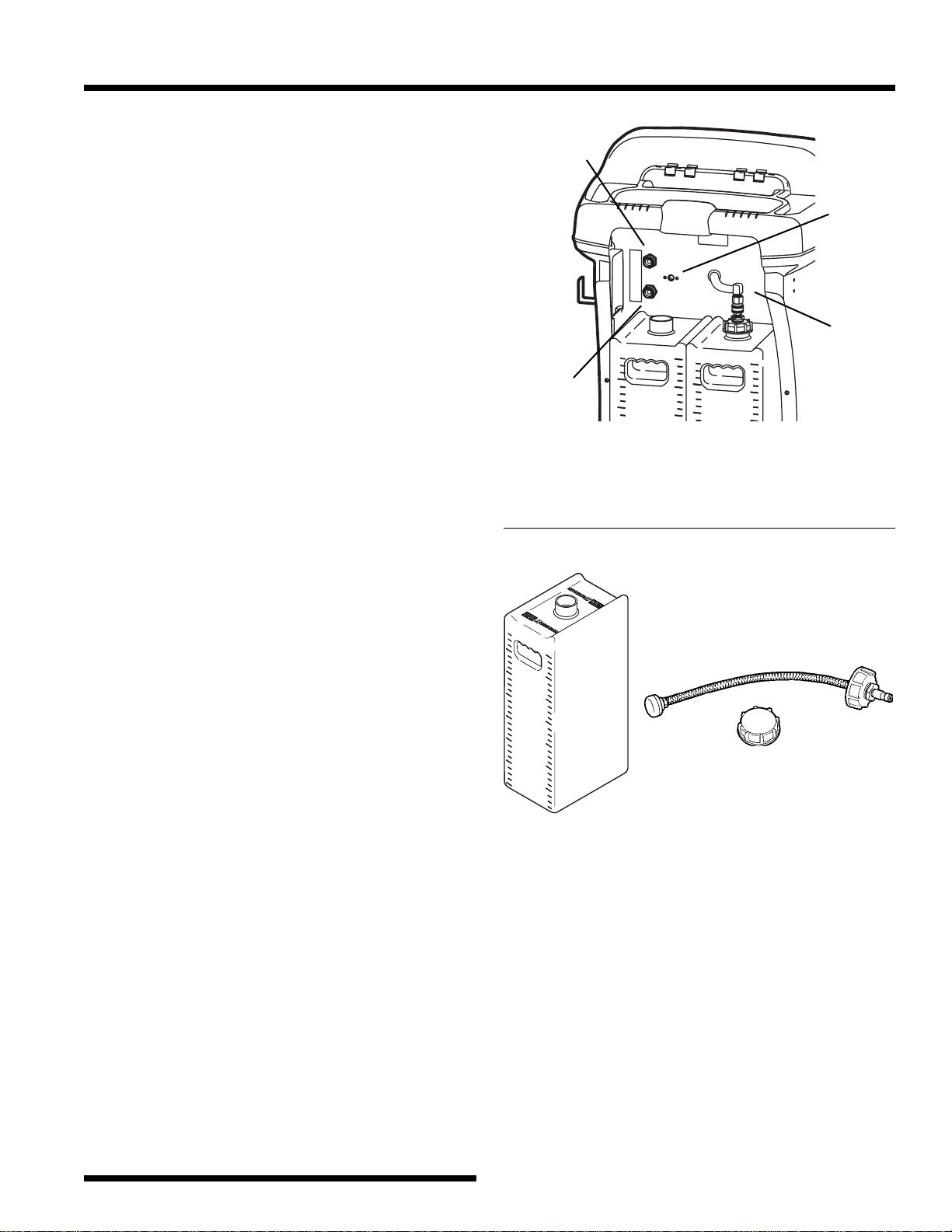
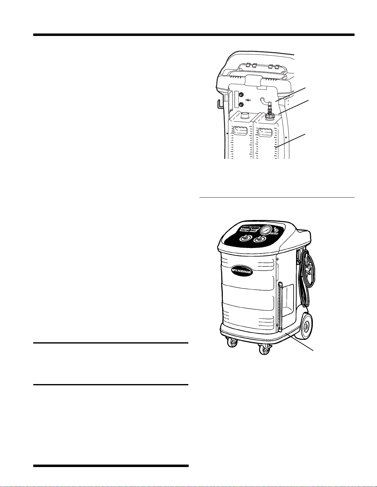
Pressure Regulator
Sight Gauge for Waste Tank
Impact-resistant
Polypropylene Cabinet
Hoses may be
stored on unit.
Pressure Gauge
3
Cool Tech 75700 CoolXchange
Setup
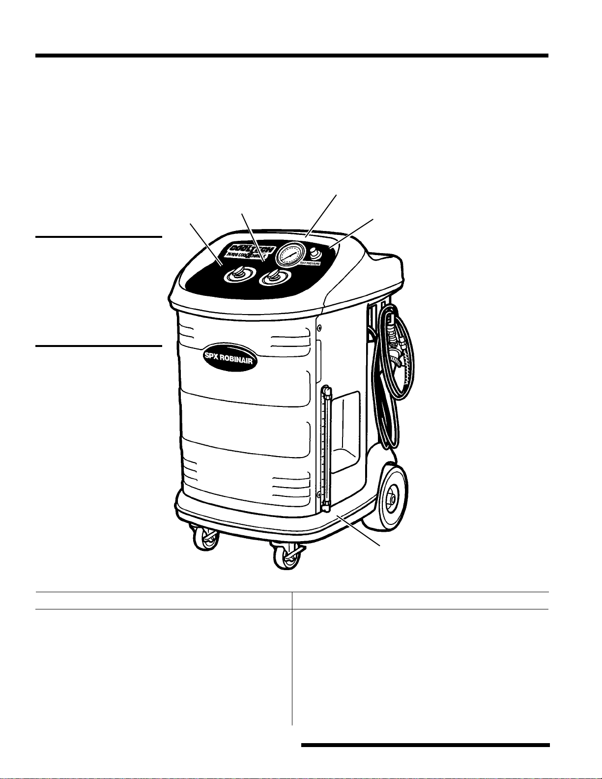
Attach Hoses
1. Attach the black hose (new coolant) to the top
coupler on the upper left side of the unit’s rear
panel. The decal next to the coupler is marked
“Coolant Outlet to Car.” See Figure 1.
2. Attach the clear hose (waste coolant) to the
bottom coupler marked “Coolant Inlet from Car.”
3. Verify Valve 1 and Valve 2 on the 75700 unit are
in the OFF position.
4. Connect an air coupler fitting (user-supplied) to
the air supply inlet. Attach a shop air line to the
fitting that is regulated to supply 80–120 psi of
clean compressed air.
Assemble Supply Tanks
The 75700 is shipped with two empty supply tanks,
which will be filled with new coolant and strapped
to the back of the unit.
1. Fill one supply tank with new coolant. Install the
dip tube cap on the tank. See Figure 2.
Note: You may fill the second supply tank with a
different type of coolant, or you may leave it
empty at this time. Install the solid cap on the
second tank.
2. Place both tanks side-by-side on the back of the
unit, and secure them with the Velcro
®
strap.
4. Attach the supply hose coupler to the dip tube
cap as shown in Figure 1.
ll
ll
l
Figure 2
Supply
Hose
Attach air
coupler
fitting (not
supplied).
Supply Tank
Dip Tube Cap
for Supply Tank
Solid Cap
for Supply Tank
20
28
24
20
28
24
20
20
28
24
20
28
24
20
27
27
Figure 1
Black Hose
(new coolant)
Clear
Hose
(waste
coolant)
2
0
1
6
1
2
8
4
2
8
2
4
2
0
1
6
1
2
8
4
Q
U
A
R
T
S
L
I
T
E
R
S
2
8
2
4
2
0
1
6
1
2
8
4
Q
U
A
R
T
S
L
I
T
E
R
S
2
7
ll
ll
l
ll
ll
l
ll
ll
l
4
© 2003 SPX Corporation
Relieve Cooling System Pressure
On some systems it is necessary to allow the cooling
system to cool before servicing the vehicle. On
vehicles that have a radiator cap, it is possible to relieve
pressure by drawing a vacuum on the overflow port.
System Inspection
Before starting the service procedure, verify :
•
the 75700 unit is connected to a supply tank
holding the correct amount and type of new
coolant for the vehicle being serviced.
•
the waste coolant tank has enough capacity to
exchange the desired amount of coolant.
Note: Running the unit with a full waste tank will
degrade the performance of the unit.
•
the vehicle ignition is in the OFF position.
•
valves 1 and 2 on the 75700 unit are OFF.
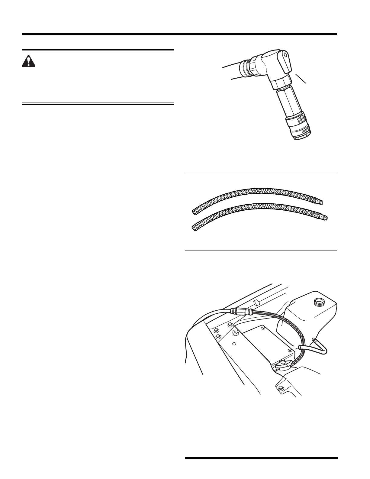
•
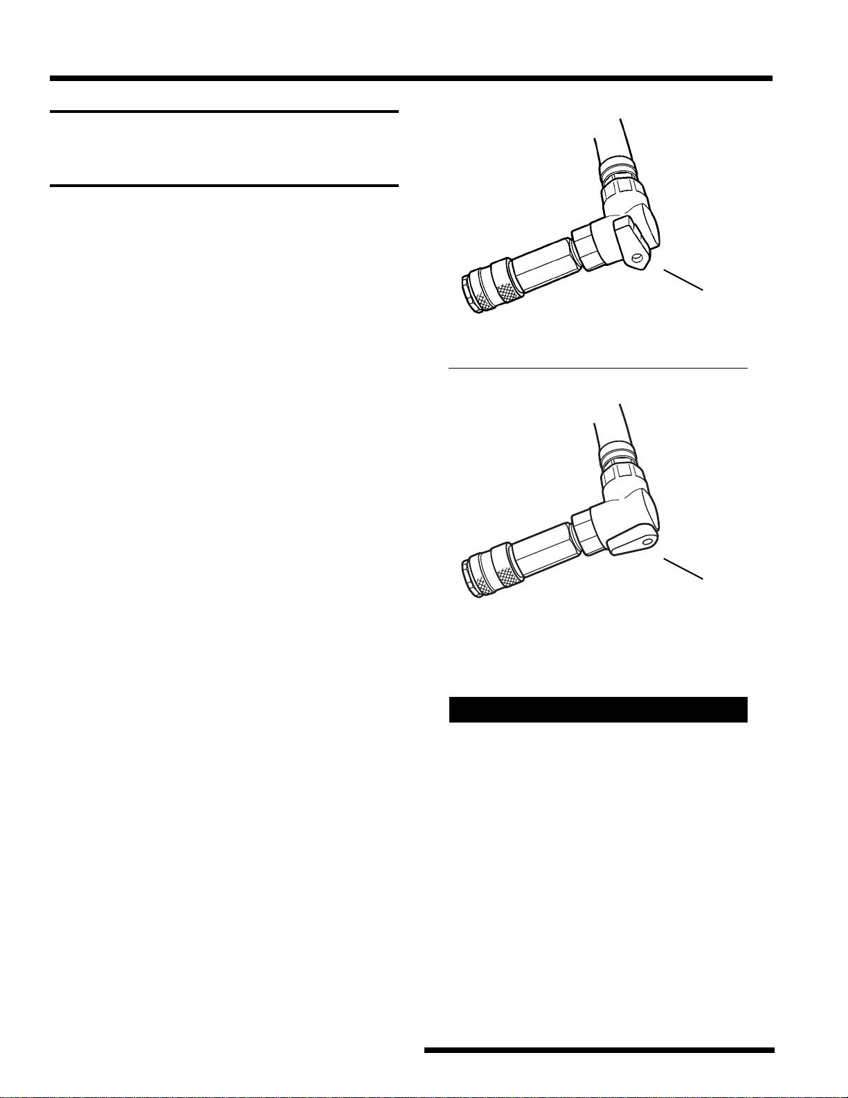
the valve on the black hose is open. See Figure 3.
•
the filter screen on the clear hose is clean.
Relieve Pressure on a Hot System
that has a Radiator Cap :
1. Remove the vehicle’s overflow tank hose from
the coolant overflow barb on the radiator neck.
2.
Two sizes of siphon tubes have been included with
the 75700 unit. See Fig. 4. Select the siphon tube
which most closely matches the size of the coolant
overflow barb on the vehicle’s radiator neck.
3. Slide the siphon tube onto the coolant overflow
barb on the radiator neck.
4. Connect the coupler end of the siphon tube to the
clear hose from the 75700 unit. See Figure 5.
5. Turn both valves on the unit to VACUUM. As the
valve in the radiator cap releases pressure,
coolant may be seen in the siphon tube.
6. After pressure is relieved, turn both valves OFF.
Figure 3
ll
ll
l
Figure 4
Figure 5
Black Hose
(new coolant)
Valve in
OPEN
position.
Siphon Tubes
Siphon tube
assembled
between clear
hose and
overflow barb
on radiator.
WARNING: Cooling systems that are hot,
are under pressure. Working on a hot cooling
system without first relieving the pressure
will result in serious personal injury.
5
Cool Tech 75700 CoolXchange
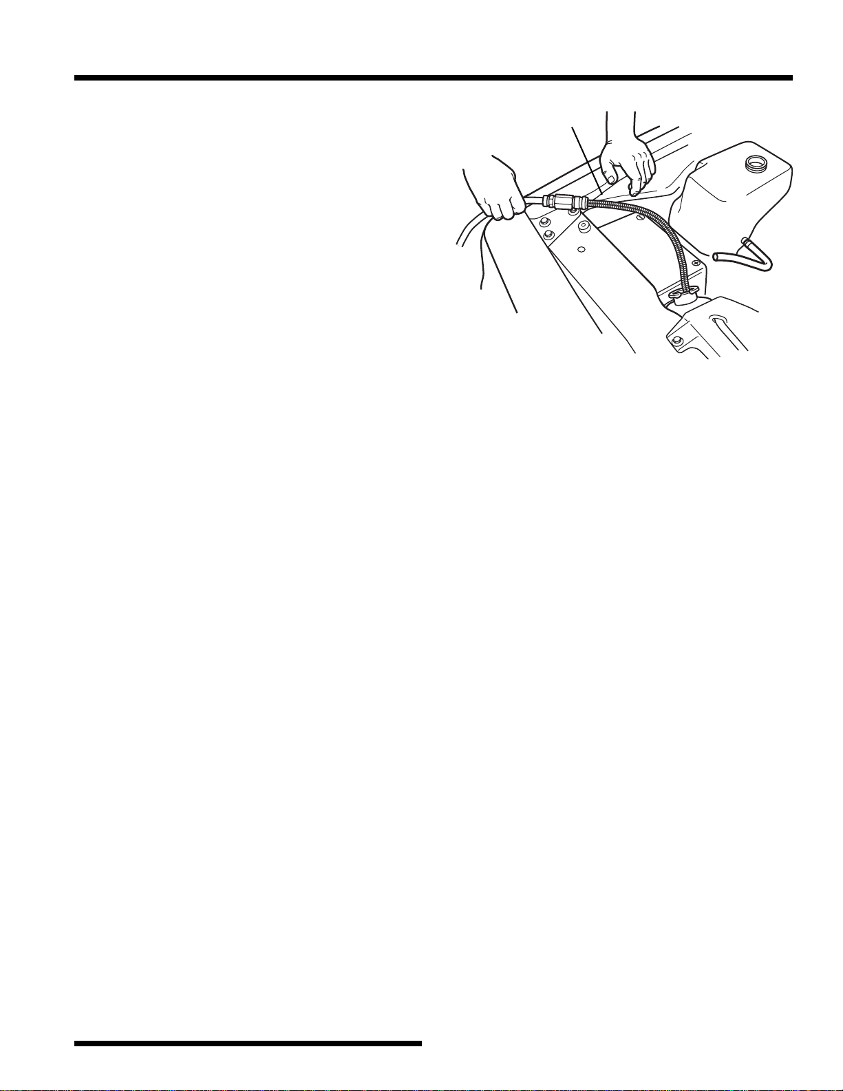
Lower the Coolant Level
1. After the cooling system has been depressurized
or cooled down, CAREFULLY remove the
coolant reservoir cap and the radiator cap.
2. With the coupler end of the siphon tube
connected to the clear hose (waste coolant) from
the 75700 unit, insert the other end of the siphon
tube into the coolant reservoir.
3. Turn both valves on the unit to VACUUM to
empty the coolant reservoir.
4. Insert the siphon tube into the radiator, and lower
the coolant level in the radiator to a level below
the upper radiator hose.
5. Turn both valves on the 75700 unit OFF.
6. Remove the siphon tube from the radiator, and
disconnect it from the clear hose.
7. Reinstall any disconnected hoses on the vehicle.
8. Reinstall the radiator cap and coolant reservoir
cap.
Figure 6
ll
ll
l
Siphon Tube
Use siphon tube to
lower coolant level
in radiator.
6
© 2003 SPX Corporation
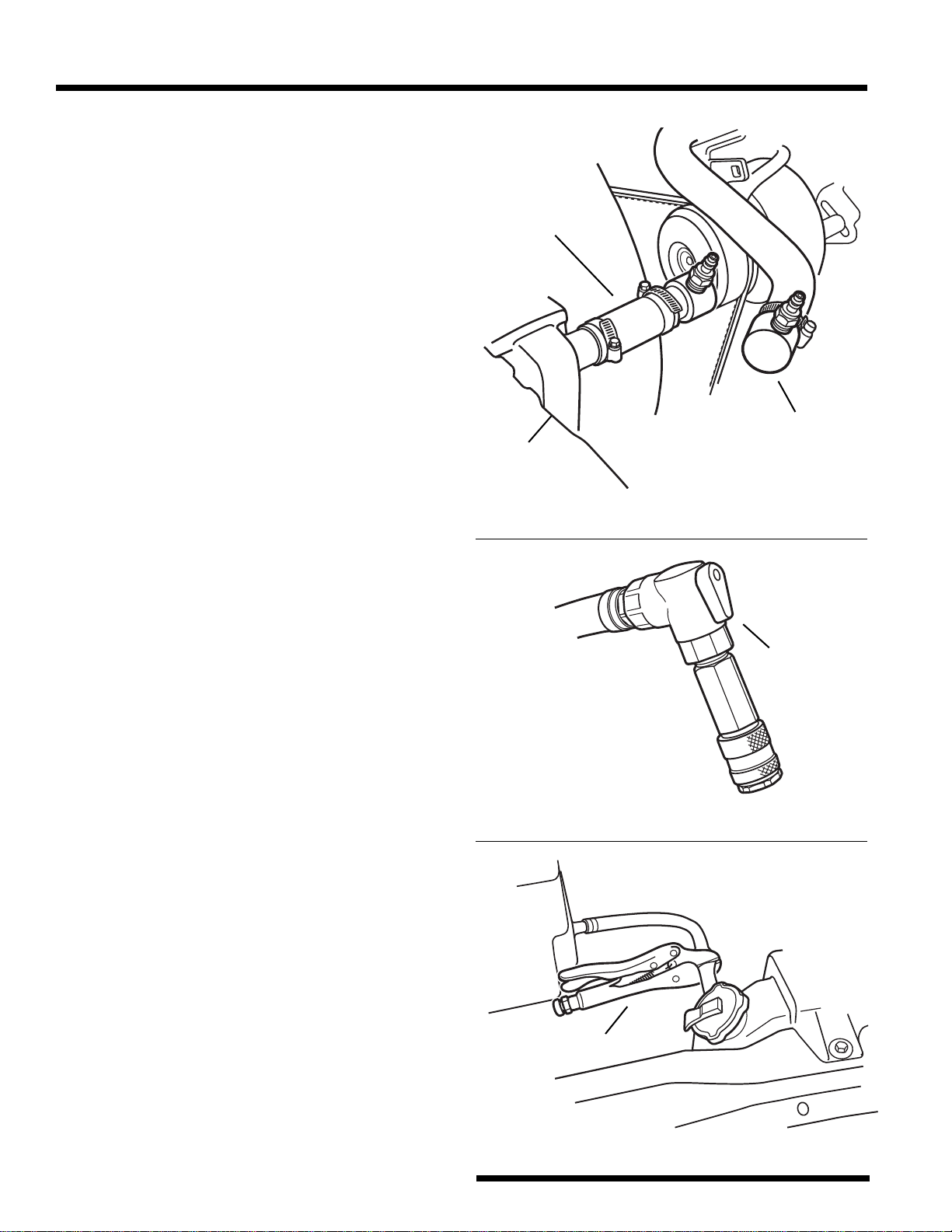
Vehicle Connections
The upper radiator hose may be disconnected either
where it connects to the radiator or where it
connects to the engine, whichever is most
convenient on the vehicle being serviced.
1. Disconnect the upper radiator hose from the
radiator or the engine.
2. Insert a step adapter into the radiator hose. See
Figure 7.
3. Select an adapter hose that has the same inner
diameter as the radiator hose. Clamp a step
adapter to the hose, and then clamp the assembly
to the hose barb where the upper radiator hose
was connected.
4. Connect the clear hose (waste coolant) to the step
adapter leading into the radiator.
5. Connect the black hose (new coolant) to the step
adapter leading into the engine. The valve on the
black hose should be OPEN. See Figure 8.
6. Pinch off the coolant overflow hose and any
other hoses connected to the coolant reservoir.
See Figure 9.
Figure 7
ll
ll
l
ll
ll
l
Figure 8
ll
ll
l
Figure 9
ll
ll
l
Hose / Step
Adapter
Assembly
Step
Adapter
Radiator
Black Hose
(new coolant)
Valve in
OPEN
position.
Coolant overflow
hose pinched off.
ll
ll
l
7
Cool Tech 75700 CoolXchange
Pressure Test
This procedure checks the coolant system for leaks.
A drop in pressure indicates a leak in the system
that must be repaired before refilling the system
with coolant.
IMPORTANT: For correct operation of the
75700 unit, adjust Valve 1 and Valve 2 in the
sequence specified in these instructions.
1. Turn the regulator on the 75700 control panel
counterclockwise (CCW) to lower the test
pressure. See Figure 10.
Note: Adjusting the regulator requires pulling up
on the regulator knob, and then turning the knob.
2. Turn Valve 1 to PRESSURE TEST.
3. Turn Valve 2 to PRESSURIZE.
4. Adjust the regulator clockwise to the correct test
pressure.
ll
ll
l
Figure 10
ll
ll
l
Valve 1
Valve 2
CAUTION: To prevent damage to the
vehicle, test pressure must range BELOW the
pressure indicated on the radiator cap,
overflow cap, or vehicle specifications.
Pressure Gauge
Regulator
5. Turn Valve 2 to HOLD.
6. Observe the pressure gauge on the control panel:
•
a constant pressure reading indicates no leaks
in the system;
•
a drop in pressure indicates a leak in the system
that must be repaired.
Note: The cooling system may need to be
pressurized more than once to equalize test
pressure throughout the system.
7. If a leak must be repaired, turn both valves to
VACUUM to relieve pressure. Perform repairs,
and repeat the Pressure Test.
If no repairs are needed, proceed to the Exchange
Procedure.
8
© 2003 SPX Corporation
Exchange Process
IMPORTANT: For correct operation of the
75700 unit, adjust Valve 1 and Valve 2 in the
sequence specified in these instructions.
1. Note the level of coolant in either the sight gauge
for the waste coolant tank or the new coolant
tank on the back of the unit.
2. Turn Valve 1 to EXCHANGE.
3. Turn Valve 2 to EXCHANGE.
4. Watch the fluid level indicator. After exchanging
the correct amount of coolant (based on the
vehicle’s cooling system capacity), turn Valve 1
OFF. Turn Valve 2 OFF.
Note: The coolant running through the waste
hose at this time should be clean. If not, continue
the exchange process until the coolant running
through the waste hose is clean.
Complete the Exchange Process
This procedure will top off the coolant in the
radiator and fill the coolant overflow reservoir.
1. Remove the step adapters and hoses. Reassemble
the upper radiator hose to the vehicle.
2. Release any pinched-off hoses.
3. Connect the siphon tube to the black hose (new
coolant).
4. Remove the radiator cap and/or coolant reservoir
cap.
5. Close the valve on the end of the black hose
(new coolant). See Figure 11.
6. Turn both valves on the 75700 to EXCHANGE.
7. Insert the siphon hose into the radiator and/or
coolant overflow reservoir, and open the valve on
the end of the black hose. Top off the coolant in
the radiator, and fill the coolant overflow
reservoir to the FULL indicator.
8. Replace the radiator cap and coolant reservoir
cap.
9. Start the engine to purge any air in the system.
Repeat the procedure to top off the coolant
system as needed.
Figure 11
ll
ll
l
ll
ll
l
Valve in
CLOSED
position.
Valve in
OPEN
position.
Black Hose
(new coolant)
Black Hose
(new coolant)
Tech Tip
Some vehicles require a different vehicle hookup
due to the way the coolant flows through the
system.
If, during the exchange process, you can’t hear
the pump running, and the flow rate is slower than
usual, it may be necessary to change the way the
hoses are connected to the vehicle.
1. Connect the clear hose (waste coolant) to the
step adapter leading into the engine.
2. Connect the black hose (new coolant) to the
step adapter leading into the radiator. The valve
on the black hose should be OPEN.
3. Leave the coolant overflow hose and any other
hoses connected to the coolant reservoir
pinched off.
4. Repeat the Exchange Process.
9
Cool Tech 75700 CoolXchange
Maintenance
Changing Supply Tanks
This procedure outlines how to switch supply tanks
so the 75700 will exchange the correct type of
coolant for the vehicle being serviced.
1. Disconnect the supply hose from the dip tube
cap. See Figure 12. Remove the dip tube cap.
2. Connect the siphon tube to the black hose (new
coolant).
3. Insert the other end of the siphon tube into the
supply tank.
4. Turn the valves on the 75700 to EXCHANGE
until coolant stops flowing in the siphon tube.
5. Turn the valves on the 75700 OFF.
6. Connect the dip tube cap to a supply tank
containing the type of coolant that is correct for
the vehicle being serviced.
7. Connect the supply hose to the dip tube cap.
Emptying the Waste Tank
Running the 75700 unit with a full waste tank will
degrade the performance of the unit.
1. Connect the siphon tube to the black hose (new
coolant).
2. Insert the other end of the siphon tube into a
waste barrel.
3. Turn both valves on the 75700 to EMPTY
WASTE.
4. Watch the sight glass for the waste tank. See
Figure 13. Empty the tank completely.
IMPORTANT: Do not leave any waste
coolant in the black hose because it
functions as the new coolant hose when
servicing a vehicle.
Figure 12
ll
ll
l
ll
ll
l
Figure 13
Supply Hose
Waste Tank
Sight Glass
2
0
1
6
2
8
2
4
2
0
1
6
Q
U
L
I
2
8
2
4
2
0
1
6
Q
U
L
I
2
0
1
6
2
8
2
4
2
0
1
6
Q
U
A
L
I
T
2
8
2
4
2
0
1
6
Q
U
A
L
I
T
2
7
2
7
Dip Tube Cap
ll
ll
l
Supply Tank
ll
ll
l
10
© 2003 SPX Corporation
Maintenance
Cleaning the Filter
Sediment will collect in the filter that is installed on
the waste hose. See Figure 14. Routinely clean the
filter to keep the unit operating correctly.
1. Unthread the cap from the filter body.
2. Rinse the screen and the inside of the cap under
running water.
3. Reassemble the filter.
Figure 14
Filter
Clear Hose
(waste coolant)
11
Cool Tech 75700 CoolXchange
Troubleshooting
Coolant exchanger does not
operate.
Unit does not relieve pressure
in vehicle cooling system.
OR
Unit does not lower coolant
level in radiator or coolant
reservoir.
Unit does not hold pressure
during pressure test.
No, or slow, exchange.
1. Air supply is not connected to
unit.
1. Filter screen on waste coolant
hose is plugged.
2. Waste coolant tank is full.
3. Air supply pressure is too low.
4. Unit hoses are assembled
incorrectly.
1. Hoses connected to coolant
reservoir not pinched closed.
2. Test pressure is too high.
3. Leak in cooling system.
1. Vehicle requires a different
hookup.
2. Valve on new coolant hose not
completely OPEN.
3. Filter screen on waste coolant
hose is plugged.
1. Attach shop air line to unit that
is regulated to supply 80–120 psi
of clean compressed air. Refer
to “Setup” in this manual.
1. Unthread cap from filter; rinse
screen and inside of cap under
running water. See “Mainte-
nance.”
2. Connect siphon tube to black
hose; insert tube into waste
barrel; turn valves to EMPTY
WASTE. See “Maintenance.”
3. Regulate shop air line to 80–
120 psi of clean compressed air.
See “Setup.”
4. Attach black hose to top
coupler; attach clear hose to
bottom coupler. See “Setup.”
1. Use pliers to pinch off coolant
overflow hose and other hoses
connected to coolant reservoir.
Refer to “Vehicle Connections.”
2. Test pressure must be below
pressure indicated on radiator
cap, overflow cap, or vehicle
specs. See “Pressure Test.”
3. Repair leak and repeat “Pres-
sure Test.”
1. Connect clear hose to engine;
connect black hose to radiator.
See Tech Tip in “Exchange
Process.”
2. Open valve. See “Exchange
Process.”
3. Unthread cap from filter; rinse
screen and inside of cap under
running water. See “Mainte-
nance.”
contd.
Symptom Cause Solution
12
© 2003 SPX Corporation
Troubleshooting
Symptom Cause Solution
No, or slow, exchange
contd.
Coolant level in coolant
reservoir rising or overflowing
during exchange procedure.
Fluid level in new coolant tank
does not decrease during
exchange.
4. Waste coolant tank is full.
5. Air supply pressure to unit is
too low.
6. Hoses are incorrectly
assembled to 75700 unit.
1. Hoses connected to coolant
reservoir not pinched closed.
1. Coolant supply hose not
connected to new tank.
2. Valve on new coolant hose not
completely OPEN.
4. Connect siphon tube to black
hose; insert tube into waste
barrel; turn valves to EMPTY
WASTE. See “Maintenance.”
5. Regulate shop air line to 80–
120 psi of clean compressed air.
See “Setup.”
6. Attach black hose to top
coupler; attach clear hose to
bottom coupler. See “Setup.”
1. Use pliers to pinch off coolant
overflow hose and other hoses
connected to coolant reservoir.
Refer to “Vehicle Connections.”
1. Attach coolant supply hose to
dip tube cap on supply tank. See
“Setup.”
2. Open valve. See “Exchange
Process.”
13
Cool Tech 75700 CoolXchange
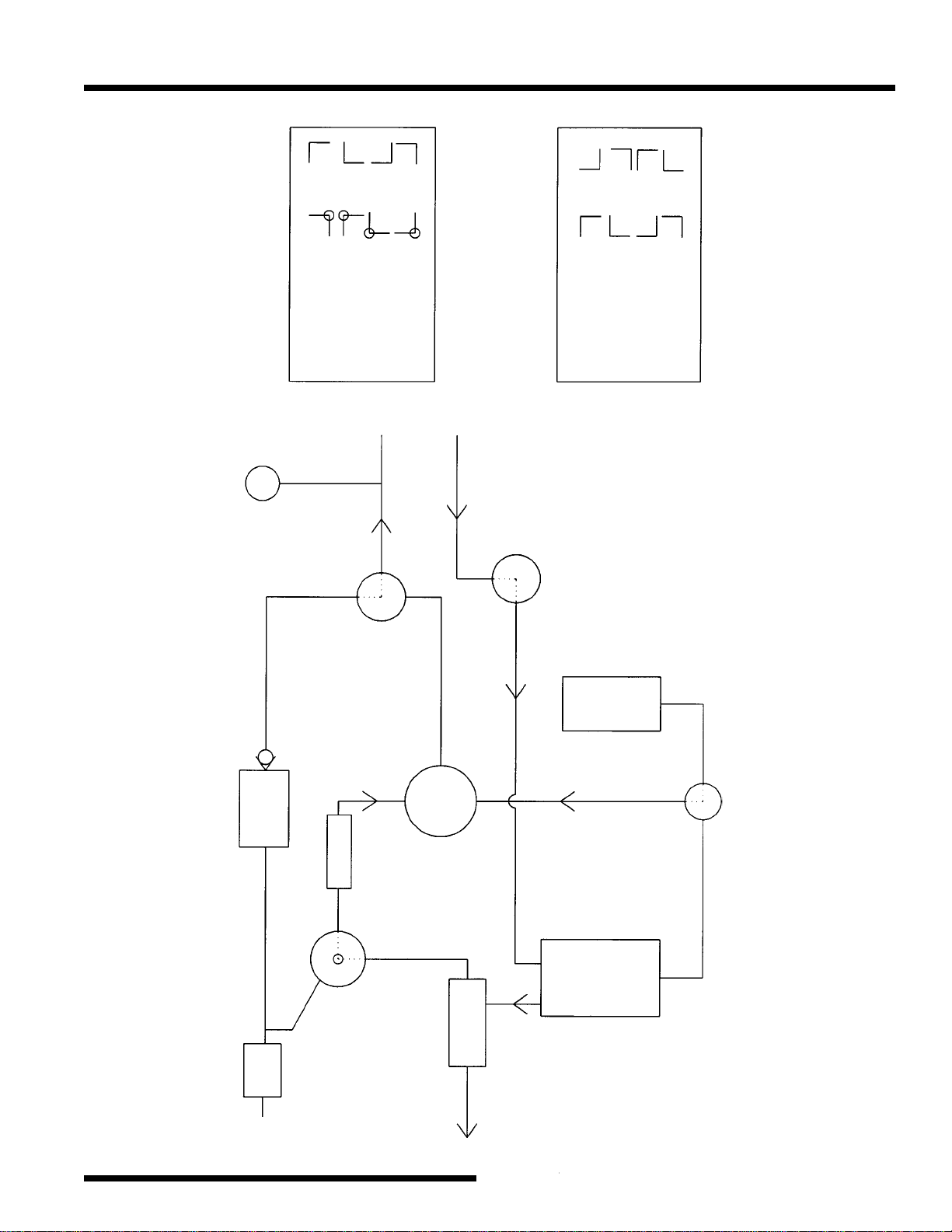
Flow Chart
Air In
Filter /
Reg
Air
Regulator
Valve 1
Bottom
Valve 2
Top
Venturi
Pump
Waste Tank
New
Tank
Valve 1
Top
Regulator
P
Valve 1 Flow Paths
OFF / Pressure Test
Vacuum
Exchange
Empty Waste
Valve 2 Flow Paths
OFF
Exchange / Vacuum
Pressurize
Hold
Bottom Top
Top Bottom
Valve 2
Bottom
Exhaust
14
© 2003 SPX Corporation
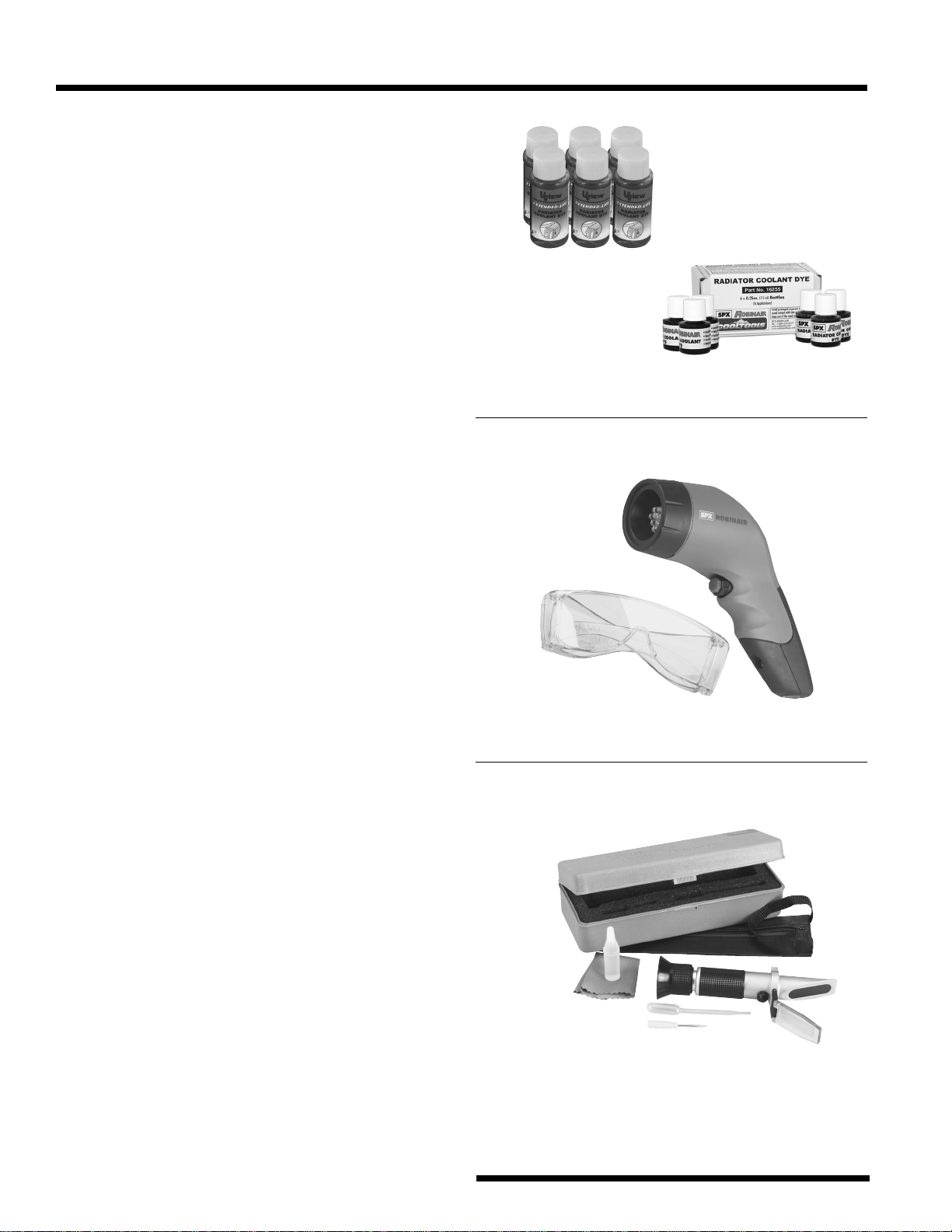
Accessories
Here are some optional accessories, available from
SPX Robinair, to help you take the guesswork out
of servicing cooling systems.
Radiator Coolant Dye
•
Pinpoint leaks in radiators, water pumps, head
gaskets, and hoses and fittings.
•
Extended-life dye is formulated for use in
extended-life coolants, which elimates the color
distortion problem found with existing radiator
coolant dyes.
•
Extended-life dye is for use with red, orange, or
yellow extended-life coolants.
•
Each bottle services one vehicle.
No. 16266 – Extended-life radiator coolant dye.
Six (1 oz. / 30 ml) bottles.
No. 16255 – Standard radiator coolant dye.
Six (.25 oz. / 7.5 ml) bottles.
Cordless / Rechargeable True UV Light
•
12 LEDs produce high-intensity true UV light.
(100,000 hour LED bulbs.)
•
Nickel metal hydride battery (does not develop a
memory). Battery life is 3 hours (continuously
ON). Includes battery charger and UV-enhancing
glasses.
•
1-year warranty.
No. 16345 – Cordless & rechargeable true UV
light. Wt., 9 oz.
Coolant and Battery Refractometer
•
Measures the freezing point of either propylene
or ethylene-glycol based cooling systems.
•
Checks electrolyte solution strength in batteries.
•
Features high-quality optics with ultra-smooth
focus.
No. 75240 – Coolant and battery refractometer.
Coolant scale range: 32° F to -60° F.
No. 75245 – Coolant and battery refractometer.
Coolant scale range: 0° C to -50° C.
16266
16255
16345
75240
75245
15
Cool Tech 75700 CoolXchange
Accessories
4510-8
4510-10
4510-12
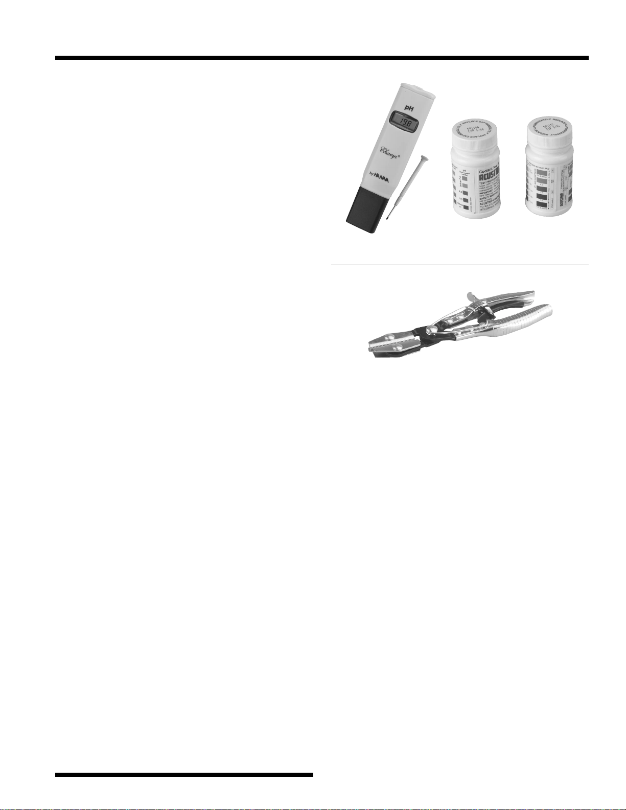
Econo-Clean Coolant Service Accessories
•
To ensure coolant will provide adequate
protection to the vehicle, the coolant should be
adjusted to the manufacturer’s specifications.
These accessories will help you quickly test
coolant.
No. 75133 – Pocket pH pen. Quickly shows the pH
level of the coolant, whether used or recycled.
No. 75134 – Coolant test strips. Bottle of 70 strips;
just dip a strip in coolant, and it shows freezing
point and pH.
No. 75234 – 3-Way coolant test strips for the
heavy-duty truck market. Just dip a strip in coolant,
and it shows freezing point, pH, and nitrite.
Hose Pinch-off Pliers
•
Shuts off flow through vacuum lines, fuel lines,
coolant lines, etc.
•
Ratchet mechanism holds pivoting jaws tightly in
place. Heavy-duty swivel jaws pivot to ensure
parallel pinching.
•
Three different sizes of pliers are available.
No. 4510-8 – 8 in. tool for small hoses & tight
areas.
No. 4510-10 – 10 in. tool for radiator & vacuum
lines.
No. 4510-12 – 12 in. tool for radiator & vacuum
lines.
75133
75234 75134
16
© 2003 SPX Corporation
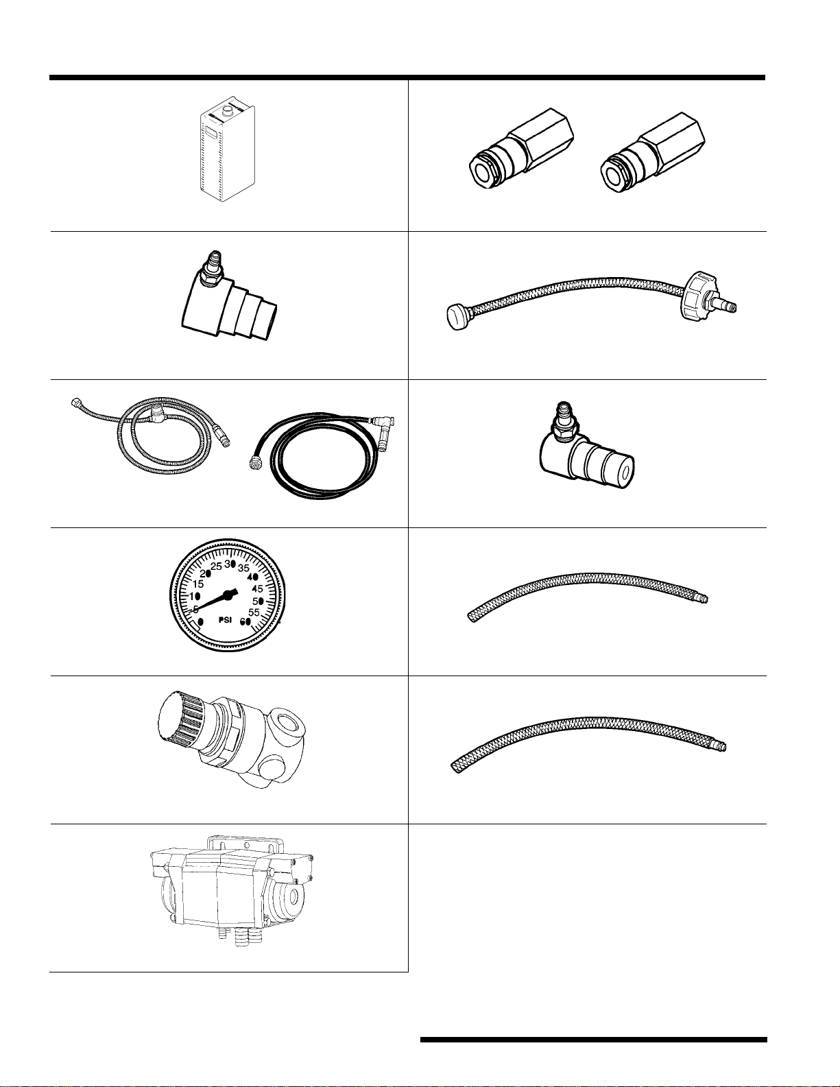
Replacement Parts List
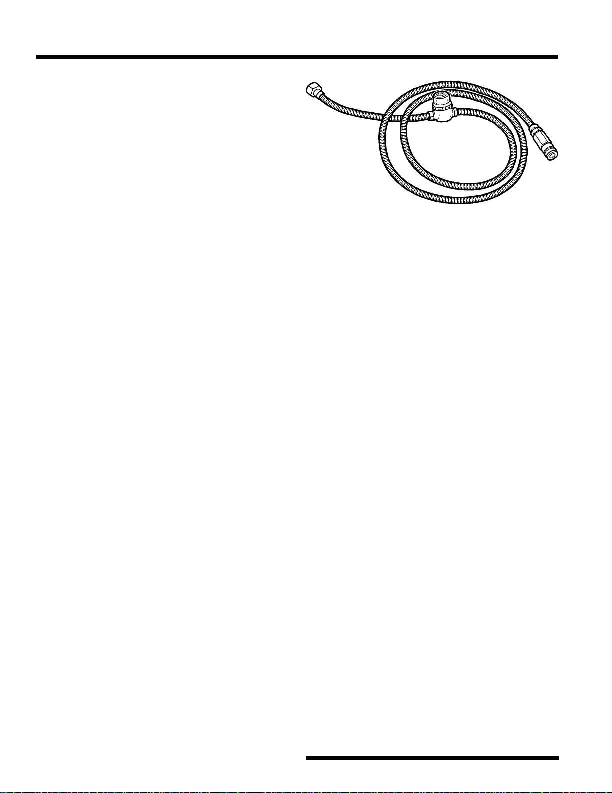
No. 75117 Replacement Hose Set
No. 75118 Replacement Pressure Gauge
No. 75119 Replacement Pressure Regulator
No. 75123 Replacement Pump Assembly
No. 75370 Replacement Supply Tank (7 gal.) No. 75125 Quick Coupler Set
No. 75116 Step Adapter (2.25
{
2
{
1.75) No. 75130 Dip Tube Assembly
No. 75491 Step Adapter (1.5
{
1.375
{
1.25)
No. 75492 Siphon Hose (5/16")
No. 75493 Siphon Hose (3/8")
(1) Clear hose
(waste coolant)
(1) Black hose
(new coolant)
2
0
1
6
1
2
8
4
2
8
2
4
2
0
1
6
1
2
8
4
Q
U
A
R
T
S
L
I
T
E
R
S
2
8
2
4
2
0
1
6
1
2
8
4
Q
U
A
R
T
S
L
I
T
E
R
S
2
7

Limited
Warranty
This product is warranted to be free from defects in workmanship, materials, and
components for a period of one year from date of purchase. All parts and labor
required to repair defective products covered under the warranty will be at no
charge.
The following restrictions apply:
1. The limited warranty applies to the original purchaser only.
2. The warranty applies to the product in normal usage situations only, as de-
scribed in the Operating Manual. The product must also be serviced and main-
tained as specified.
3. If the product fails, it will be repaired or replaced at the option of the manufac-
turer.
4. Transportation charges for warranty service will be reimbursed by the factory
upon verification of the warranty claim and submission of a freight bill for
normal ground service. Approval from the manufacturer must be obtained prior
to shipping to an authorized service center.
5. Warranty service claims are subject to authorized inspection for product
defect(s).
6. The manufacturer shall not be responsible for any additional costs associated
with a product failure including, but not limited to, loss of work time, loss of
coolant, and unauthorized shipping and/or labor charges.
7. All warranty service claims must be made within the specified warranty period.
Proof-of-purchase date must be supplied to the manufacturer.
This Limited Warranty does NOT apply if:
• The product, or product part, is broken by accident.
• The product is misused, tampered with, or modified.
• The product has been used for any purpose other than exchanging and testing
engine coolant.
521723 (Rev. C, 9-08-04) 75700 Coolant Exchanger © 2003 SPX Corporation
Visit our web site at
www.robinair.com
or
Call toll-free
1-800-822-5561
in the continental U.S. and Canada.
In all other locations, contact your local distributor.
To help us serve you better,
be prepared to provide the model number,
serial number, and date of purchase of your unit.
To validate your warranty,
complete the warranty card attached to your unit,
and return it within ten days from date of purchase.
If your unit needs repairs or replacement parts,
please contact a service center in your area.
For help locating a service center, visit our web site at
www.robinair.com
%
Due to ongoing product improvements,
we reserve the right
to change design, specifications, and materials without notice.
SPX Corporation
655 Eisenhower Drive
Owatonna MN 55060
Customer Service: 1-800-533-6127
Fax : 1-800-322-2890
Technical Service : 1-800-822-5561
Fax : 1-800-822-7805
Website : www.robinair.com
