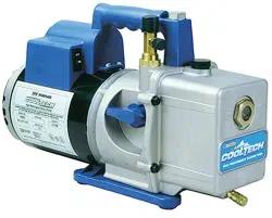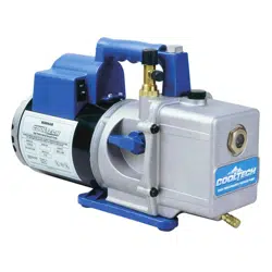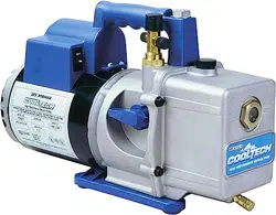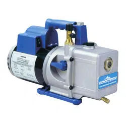
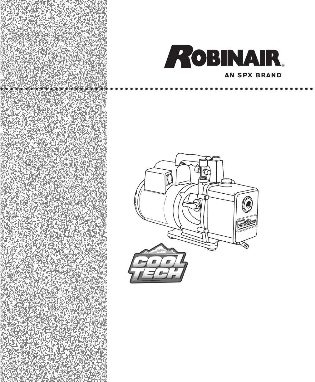
High Performance Vacuum Pump
Models 15400 and 15600
Operating
M
anual
Pump Specications
Model 15400 15600
Free Air Displacement 4 CFM 6 CFM
Stages 2 2
Motor Speed 1725 RPM 1725 RPM
Voltage +10% 115V 60 HZ 115V 60 HZ
Factory Micron Rating 15 microns 15 microns
Approximate Oil Capacity 15 oz. 15 oz.
Weight 27 lbs. 27 lbs.
Width 5
5
/8 in. 5
5
/8 in.
Height 9
3
/4 in. 9
3
/4 in.
Length 15
1
/2 in. 15
1
/2 in.
Intake
1
/2" and
1
/4"
1
/4",
3
/8", and
1
/2"
SAE MFL SAE MFL
Min. Starting Temp.
(at 90% Voltage) 32
°
F 32
°
F
Motor Size
1
/3 hp
1
/3 hp
Capacitor Start Capacitor Start
Operating Temp. 155
o
F 155
o
F
Note: 1. All motors are internally protected (automatic reset).
2. Operating temperatures are typical for normal operating conditions.
Due to ongoing product improvements, we reserve the right
to change design, specications, and materials without notice.
SPX
655 EiSEnhowEr DrivE
owatonna, Mn 55060-0995 USa
tEchnical SErvicES: 1-800-822-5561
FaX: 1-866-259-1241
cUStoMEr SErvicE: 1-800-533-6127
FaX: 1-800-283-8665
wEb SitE: www.robinair. coM
110973 Rev. E November 16, 2011 © SPX

1
CoolTech
®
High Performance Vacuum Pumps
CongratulationsonpurchasingoneofRobinair’stopqualityCoolTech
®
vacuumpumps.Yourpumphasbeenengineeredspecicallyforair
conditioningandrefrigerationservice,andisbuiltwithRobinair’s
provenoffsetrotaryvaneforfast,thoroughevacuation.You’llappreciate
thesekeyfeatures...
Iso-Valve
TM
AllowsthepumptobeshutoffwhilestillconnectedtotheA/C-R
system,whichishandyforcheckingrateofrise.Withthevalvehandlein
theOPENposition,thepumpisopentothesystembeingevacuated.In
theCLOSEDposition,thepumpisisolatedfromthesystem.
Thetwo-stage,offset,rotaryvanedesignprovidespowerful,quiet,
highvacuumcapabilityandensuresmoistureremoval,whilethehigh
pumpingcapacityreducesevacuationtime.
Theintakelterpreventsforeignmatterfromenteringthepumping
chamber,andaninternalexhaustlterseparatesoilvaporfromthe
exhaustow.
Exhaustisexpelledthroughthehandletodirectitawayfromtheservice
technician.
Apreciseamountofatmosphericairisintroducedintothepump,
preventingcondensationofmoisturevaporandhelpingmaintainthe
purityofthepumpoil.Byusingthegasballast,thepumpoperatesmore
efcientlyandpumplifeisextended.
Theone-piece,moldedhandlemakesiteasytocarrythepumptoand
fromjobsites,andthehandlestayscooltothetouchduringoperation.
Thepumpmeasuresjust15
1
/2"long,whilealuminumhousingandoffset
rotaryvaneskeepthepumpweightlow,makingiteasytocarry.
High
Vacuum
Rating
Lifetime
Filtration
Directed
Exhaust
Gas
Ballast
Sure-Grip
Handle
Compact
Design
For use on A/C-R systems using CFCs, HCFCs, and HFCs in conjunction
with mineral oil, ester oil, alkylbenzene oil, and PAG oil as lubricants.
Not for use with ammonia or lithium bromide systems. Not for use with
ammable refrigerants.
2
WARNING!
Wear safety goggles when working with refrigerants. Contact with
refrigerants may cause eye injury.
Incorrect use or electrical connections may cause electrical shock.
Read and follow instructions carefully, and take precautions to avoid
electrical shock hazards. All associated devices must be correctly
grounded before energizing circuits.
The normal operating temperature will cause certain external
portions of the pump to be hot to the touch. Do not touch the pump
housing or motor during operation.
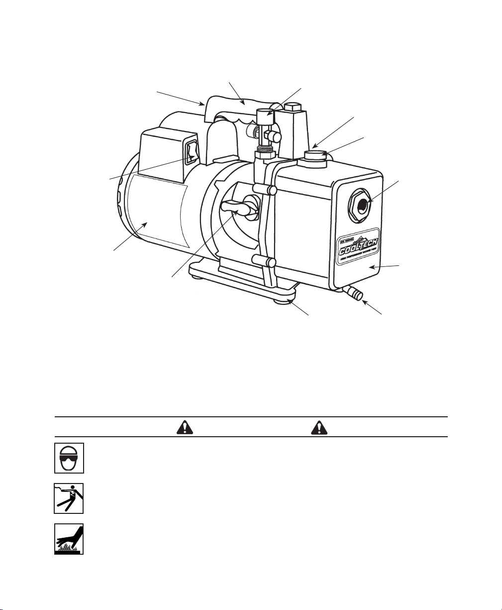
Pump
Components
1. IntakeFitting
2. GasBallastValve
(locatedbesidehandlebase)
3. OilFillPort
4. SightGlass
5. Die-CastAluminumHousing
6. OilDrain
7. MoldedPolycarbonateBase
8. Iso-Valve
TM
(isolatesthepumpfromthesystem)
9. High-TorqueMotor
10. PowerSwitch
11. Through-The-HandleExhaust
12. Sure-GripHandle
1
2
3
4
5
6
7
8
9
10
11
12

3
Before using your vacuum pump...
Note on Motor Voltage Connections:
Inallcases,motorsaredesignedforoperatingvoltages,plusorminus
10%ofthenormalrating(seeSPECIFICATIONS).Singlevoltage
motorsaresuppliedfullyconnectedandreadytooperate.
1.Verifythatthevoltageandfrequencyattheoutletmatchthe
specicationsonthepumpmotordecal.PlacetheON/OFFswitchin
theOFFpositionbeforeyouplugthepumpintoanoutlet.Verifythegas
ballastvalveisclosed.Removeanddiscardtheexhaustplugfromthe
endofthepump’shandle.
2.Thepumpisshippedwithoutoilinthereservoir.Beforestartingthe
pump,llitwithoil.RemovetheOILFILLcap(blackplasticplug
directlyinfrontofthehandle),andaddoiluntiltheoiljustshowsinthe
bottomofthesightglass.Theapproximateoilcapacityofthepumpis
15ounces.
3.ReplacetheOILFILLcap,andremovethecapfromoneoftheinlet
ports.OPENtheIso-Valve™.TurnONthemotorswitch.Whenthe
pumprunssmoothly,CLOSEtheIso-Valve™,andreplacethecaponthe
inletport.Thismaytakefromtwoto30secondsdependingonambient
temperature.Afterthepumprunsforapproximatelyoneminute,check
thesightglassforthecorrectoillevel—theoilshouldbeevenwiththe
sightglassOILLEVELline.Addoilifnecessary.
Note:Whenthepumpisrunning,theoillevelshouldbeevenwith
thelineonthesightglass.Underllingwillresultinpoorvacuum
performance;overllingcanresultinoilblowingfromtheexhaust.
Yourpumpisnowreadytoevacuateairconditioningandrefrigeration
systems.FollownormalserviceproceduresandtheA/C-R
manufacturer’sinstructionsforconnectionstothesystem.
CAUTION Before connecting your vacuum pump to an A/C-R system,
remove refrigerant from the system in an accepted manner.
Damage to the pump may occur if evacuation is started while
the system is under high pressure. Robinair recommends the
use of our Refrigerant Recovery and Recycling equipment.

4
To use the gas ballast feature...
MoisturefromtheA/C-Rsystemthatiscarriedintothepumpasavapor
tendstocondenseintoaliquidandcombinewiththevacuumpumpoil.
Whenmoisturecontaminatesthepumpoil,itreducesthepump’sability
toreachitsultimatedeepvacuumlevel.
Thegasballastvalvepurgesasmallamountofatmosphericairthrough
theexhaustchamber.Thisextravolumeofairmixeswiththevapor
fromtherefrigerantsystemtopreventcondensationandtohelpexhaust
moistureintheformofvaporfromthepump.
Thegasballastvalveislocatedbesidethehandle,oppositetheinlet
tting.Tousethegasballast,startthepumpandopenthegasballast
valveuntilthesystemhasreached1000–3000microns.Closethevalve
toallowthepumptopulldowntoitsultimatevacuumlevel.
Thegasballastvalvemaybeopenedorclosedatanytimeduringpump
operation.Itisfullyopenattwoturnscounterclockwise.
Note:Robinairrecommendstheuseofathermistorvacuumgaugeto
mostaccuratelymeasurevacuumlevels.
To shut down the pump after use...
Tohelpprolongpumplifeandpromoteeasystarting,followthese
proceduresforshutdown:
1.Closethemanifoldvalvebetweenthepumpandthesystem.
2.TurntheIso-Valve™totheCLOSEDposition.
3.Removethehosefromthepumpinlet.
4.TurnthepumppowerswitchtoOFF.ReturntheIso-Valve™tothe
OPENpositionforafewsecondstorelieveanyvacuuminsidethepump.
5.Captheinletporttopreventanycontaminationorlooseparticlesfrom
enteringtheport.

5
To maintain the high vacuum pump...
Formaximumperformance,Robinairrecommendschangingvacuum
pumpoilaftereachuse.
Theconditionandtypeofoilusedinanyhighvacuumpumpare
extremelyimportantindeterminingtheultimateattainablevacuum.
RobinairrecommendstheuseofourPremiumHighVacuumPumpOil.
Thisoilhasbeenspecicallyblendedtomaintainmaximumviscosityat
normalrunningtemperaturesandtoimprovecoldweatherstarts.
RobinairPremiumHighVacuumPumpOilisavailableinhandyquart
containersorinconvenientgalloncontainers.Orderbypartnumber:
13203—Quart(shipped12quartspercase)
13204—Gallon(shipped4gallonspercase)
1.Allowthepumptorununtilitiswarmedup.
2.RemovetheOILDRAINcap.Draincontaminatedoilintoasuitable
containeranddisposeofcorrectly.Oilcanbeforcedfromthepumpby
openingtheinletandpartiallyblockingtheexhaustwithaclothwhile
thepumpisrunning.Donotoperatethepumpformorethan20seconds
usingthismethod.
3.Whentheowofoilhasstopped,tiltthepumpforwardtodrain
residualoil.
4.ReplacetheOILDRAINcap.RemovetheOILFILLcap,andllthe
reservoirwithnewvacuumpumpoiluntiltheoiljustshowsatthe
bottomofthesightglass.Theapproximateoilcapacityofthepump
is15ounces.
5.Verifytheinletportsarecapped,andturnONthepump.Allowittorun
foroneminute,andchecktheoillevel.Iftheoilisbelowthesightglass
OILLEVELline,addoilslowly(withthepumprunning)untiltheoil
reachestheOILLEVELline.ReplacetheOILFILLcap,makingsurethe
inletiscappedandthedraincapistight.
6.a)Iftheoilisbadlycontaminatedwiththesludgethatformswhen
waterisallowedtocollectintheoil,youmayneedtoremovetheoil
reservoircoverandwipeitout.
Vacuum
Pump Oil
Oil
Change
Procedure

6
b)Anothermethodofdealingwithheavilycontaminatedoilistoforce
theoilfromthepumpreservoir.Todothis,allowthepumptorun
untilitiswarmedup.Whilethepumpisstillrunning,removetheoil
draincap.Slightlyrestricttheexhaust.Thiswillback-pressuretheoil
reservoirandforcetheoilfromit,carryingmorecontaminants.When
theoilceasestoow,turnoffthepump.
Repeatthisprocedureasrequireduntilthecontaminationisremoved.
ReplacetheOILDRAINcap,andrellthereservoirtothecorrectlevel
withfreshpumpoil(seeStep4).
Cleanthepumpusingonlysoapandwater.Donotusecommercial
cleanerscontainingdegreasingagentsthatcandamagepolycarbonates.
ThepumphandleandbasearemadeofLexan
®
,oneofthetoughest
polycarbonateplasticsavailable,butitissensitivetodegreasingagents.
*LexanisaregisteredtrademarkofGeneralElectric.
Troubleshooting Guide
YourCoolTech
®
pumphasbeendesignedfordependableuseandlong
life.Ifsomethingshouldgowrong,however,thefollowingguidewill
helpyougetthepumpbackintoserviceasquicklyaspossible.
Ifdisassemblyofthepumpisrequired,rstcheckyourwarranty.The
warrantymaybevoidedbymisuseorcustomertamperingthatresultsin
thepumpbeinginoperable.
Checklinevoltage.Robinairpumpsaredesignedtostartat+10%line
voltage(loaded)at32
o
F.Atextremes,however,switchingbetweenthe
startandrunwindingsmayoccur.
1.Verifytheoilisnotaresidualaccumulationfromspillage,etc.
2.Ifleakageexists,themodulecovergasketortheshaftsealmayneed
replacing.FollowtheinstructionssuppliedwithSealReplacementKit
No.15367.Ifleakageexistsintheareaoftheoildrainplug,youmay
needtoresealtheplugusingacommercialpipethreadsealer.
1.VerifytheIso-Valve™onthepumpisintheOPENposition.
2.Verifythevacuumgaugeandallconnectionsareingoodconditonand
leak-free.Conrmleakagebymonitoringthevacuumwithathermistor
gaugewhileapplyingvacuumpumpoilatconnectionsorsuspectedleak
points.Vacuumwillimprovebrieywhiletheoilissealingtheleak.
Cleaning
the Pump
Failure
To Start
Oil
Leakage
Failure
To Pull
A Good
Vacuum
7
3.Verifythepumpoilisclean.Abadlycontaminatedpumpmayrequire
severaloilushes.SeeOILCHANGEPROCEDURE.
Note:UseonlyhighvacuumpumpoilsuchasRobinair’sPremiumHigh
VacuumPumpOil.Otheroilswillpreventpull-downtoadeepvacuum.
4.Verifythegasballastknobistightlyclosed.
5.Verifytheoilisatthecorrectlevel.Formaximumpumpoperation,the
oilmustbeevenwiththeOILLEVELlineonthesightglasswhenthe
pumpisrunning.SeeOILCHANGEPROCEDURE.Donotoverll—
operatingtemperatureswillcausetheoiltoexpandsoitwillappearata
higherlevelthanwhenthepumpisnotrunning.Tochecktheoillevel,
startthepumpwiththeinletcapped.Checktheoillevelinthesight
glass.Addoilifnecessary.
Iftheseproceduresdonotcorrecttheproblem,
contactyournearestRobinairdistributor.The
distributormayrecommendanadditional
replacementpart(thismanualcontainsaparts
list)orsuggestyousendyourpumptothenearest
authorizedservicecenter.CallRobinair’stoll-free
ServiceLineforfurtherinformation:
Warranty Coverage
RobinairCoolTech
®
vacuumpumpsarewarrantedagainstdefectsin
materialandworkmanshipforoneyearofnormalusefromthedateof
purchase.Seeyourdistributorforwarrantydetails.
Apumpthatisnolongercoveredbytheone-yearwarrantyperiod,and
whichfailstooperatecorrectly,shouldbereturnedtothedistributorwith
afullwrittenexplanationoftheproblem,oryoumayreturnityourselfto
oneoftheauthorizedRobinairServiceCentersforrepair.
Priortoreturninganout-of-warrantypump,reviewallmaintenance
procedurestoavoidanunnecessaryreturn.Notethatcontaminated
oiloranincorrectoillevelwilladverselyaffectpumpperformance.
Replacementpartsareavailablefordoingyourownservice.However,
thisshouldbeconsideredonlyinout-of-warrantysituations.
Registeryourvacuumpumpatwww.robinair.com.
800-822-5561
When You
Need Help
Out of
Warranty
Product
Registration
8
INST0026
1
2
3
4
5
6
7
9
8
11
12
13
16
15
17
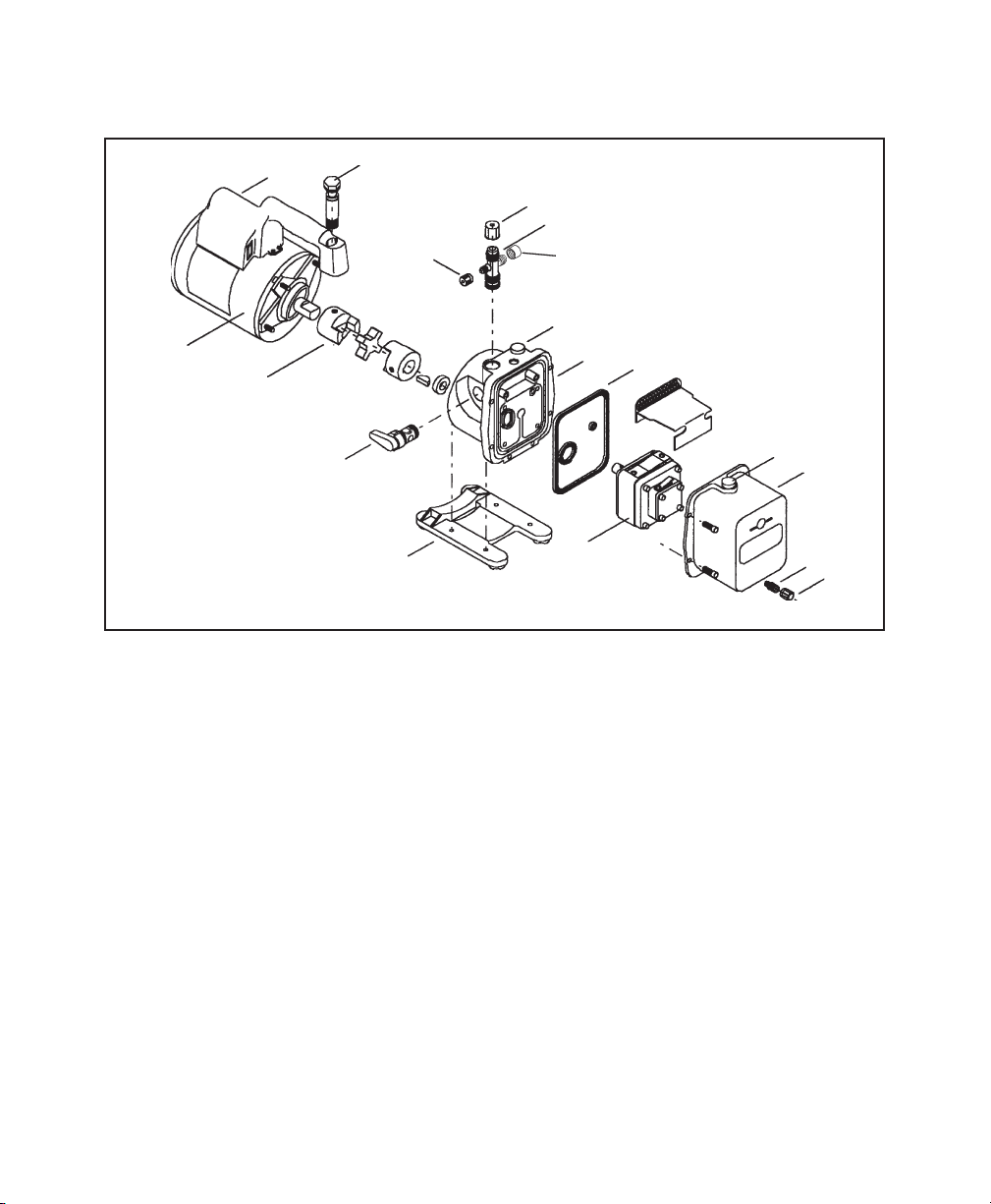
Replacement Parts
Part Figure 15400 15600
OilDrainCap(6) 1 40572 40572
OilDrainKit(includesItemNo.1) 2 48116 48116
ModuleCoverKit(includesNos.2,4,and5) 3 15337 15337
OilFillCap(includesNo.7) 4 15371 15371
IntakeFitting(includesNo.9) 8 15364 555124
IntakeCaps(
1
/4",
3
/8",and
1
/2"are;1ea.) 9 555133 555133
VentBolt(includeso-rings) 11 15338 15338
Handle,PowerCord,andSwitchAssembly 12 15366 15366
Motor 13 15365 15370
Coupling 14 48103 48103
Iso-Valve™Assembly 15 15368 15368
BaseandFootAssembly 16 15369 15369
ReplacementModule(includesNos.1through7) 17 15547 15548
SealReplacementKit(notshown) -- 15367 15367
14
99

High Performance Vacuum Pump
Models 15400 and 15600
Operating
M
anual
Pump Specications
Model 15400 15600
Free Air Displacement 4 CFM 6 CFM
Stages 2 2
Motor Speed 1725 RPM 1725 RPM
Voltage +10% 115V 60 HZ 115V 60 HZ
Factory Micron Rating 15 microns 15 microns
Approximate Oil Capacity 15 oz. 15 oz.
Weight 27 lbs. 27 lbs.
Width 5
5
/8 in. 5
5
/8 in.
Height 9
3
/4 in. 9
3
/4 in.
Length 15
1
/2 in. 15
1
/2 in.
Intake
1
/2" and
1
/4"
1
/4",
3
/8", and
1
/2"
SAE MFL SAE MFL
Min. Starting Temp.
(at 90% Voltage) 32
°
F 32
°
F
Motor Size
1
/3 hp
1
/3 hp
Capacitor Start Capacitor Start
Operating Temp. 155
o
F 155
o
F
Note: 1. All motors are internally protected (automatic reset).
2. Operating temperatures are typical for normal operating conditions.
Due to ongoing product improvements, we reserve the right
to change design, specications, and materials without notice.
SPX
655 EiSEnhowEr DrivE
owatonna, Mn 55060-0995 USa
tEchnical SErvicES: 1-800-822-5561
FaX: 1-866-259-1241
cUStoMEr SErvicE: 1-800-533-6127
FaX: 1-800-283-8665
wEb SitE: www.robinair. coM
110973 Rev. E November 16, 2011 © SPX