Loading ...
Loading ...
Loading ...
4
4. Setup
Caution! Read All Instructions and Warnings Before Installation!
Warning: Charging stations can be extremely heavy. Do not attempt to unpack or mount the charging station without
assistance. Use extreme caution when handling the charging station and be sure to follow all handling and installation
instructions. Do not attempt to install equipment without first stabilizing the charging station.
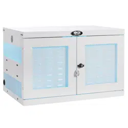
4.1 Adjusting Storage Shelf Dividers
4.2 Powering the USB Charger/Hub Unit
Your charging station comes with a storage
shelf containing adjustable dividers that can
accommodate up to 16 personal electronic
devices.
Remove any personal electronic devices stored
on the shelf tray. Then remove the blanking
panel by inserting your fingers into its left and
right holes, and lifting the blanking panel up
and pulling out
A
. To remove the shelf tray
from the cabinet, push the shelf tray forward to
disengage from the mounting hook, then pull
the tray up and out. Once the shelf is removed,
remove or rearrange a spring-wire divider by
first pulling it gently forward to disengage it
from the rear end
B
, then pull it up from the
front of the tray
C
. Repeat as necessary for
additional shelf dividers.
Once the blanking panel has been removed as shown in Section 4.1, find the USB Charger/Hub
unit’s input plug and cable located in the charging station’s bottom compartment. Push the input
plug through one of the power cord access holes located on either side of the charging station
cabinet (using the power cord access hole on the same side as the power cord manager is
recommended). Plug the power cord into the nearest 3-prong, grounded wall outlet.
Note: The power cord can optionally be routed through the charging station’s rear panel. To do so, first remove
the rubber grommet from either power cord access hole and attach it to the cable lock routing hole on the
back of the unit (see 3. Feature Identification for routing locations).
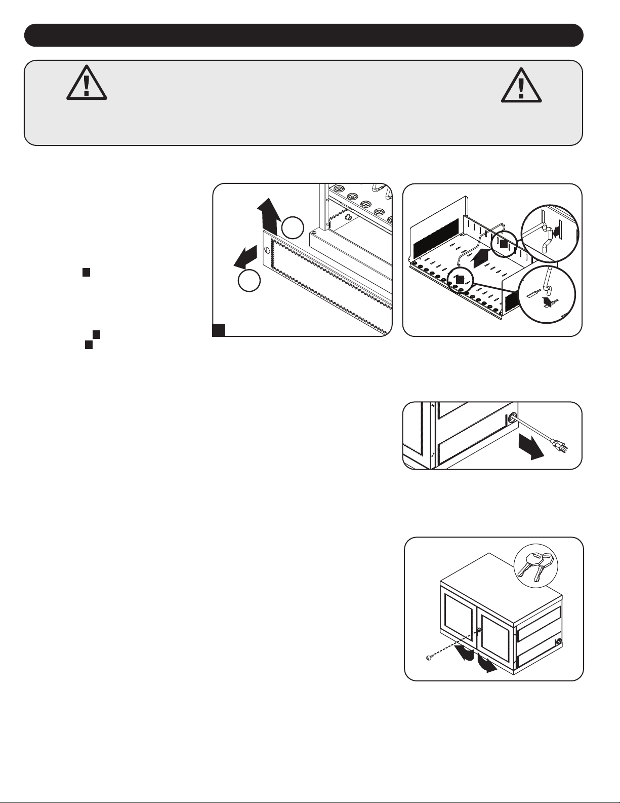
4.3 Door Locks
The split doors contain a lock that is accessible with the included keys.
B
C
1
2
A
Loading ...
Loading ...
Loading ...