Loading ...
Loading ...
Loading ...
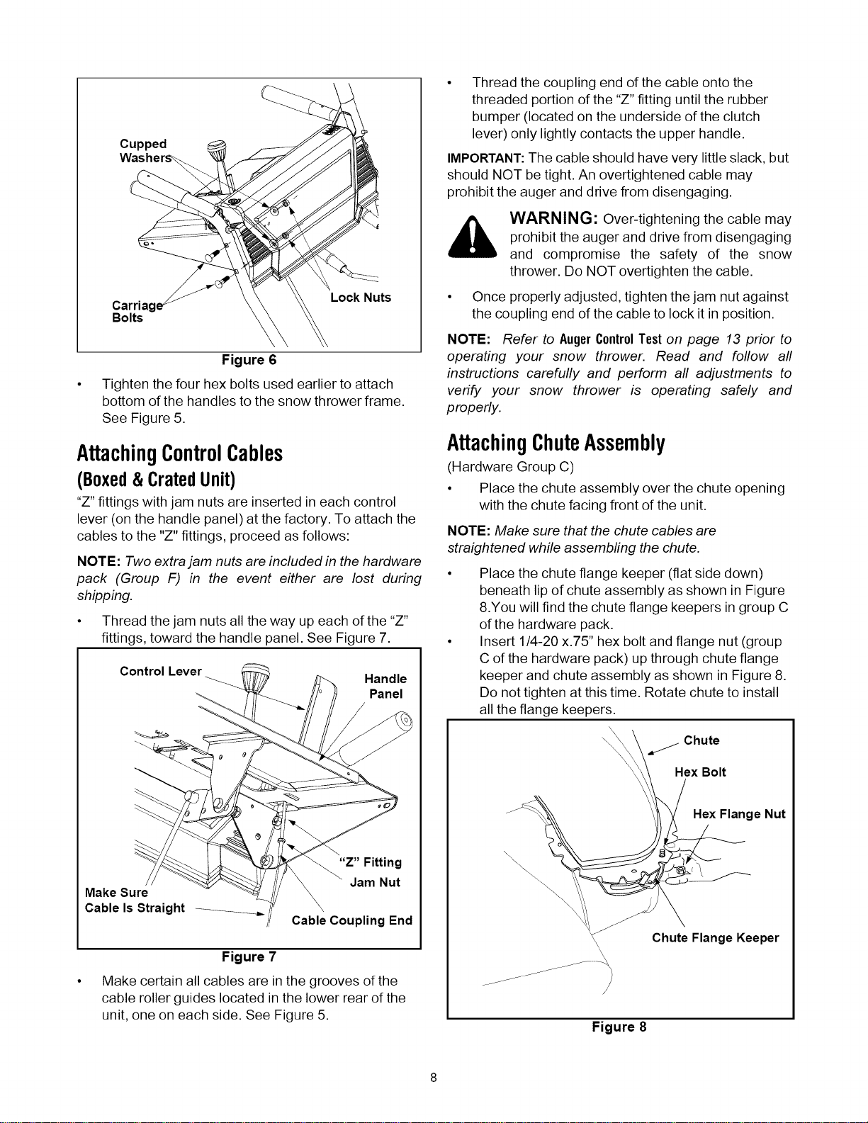
Cupped
Carriag
Bolts
Lock Nuts
Figure 6
Tighten the four hex bolts used earlier to attach
bottom of the handles to the snow thrower frame.
See Figure 5.
AttachingControlCables
(Boxed&CratedUnit)
"Z" fittings with jam nuts are inserted in each control
lever (on the handle panel) at the factory. To attach the
cables to the "Z" fittings, proceed as follows:
NOTE: Two extra jam nuts are included in the hardware
pack (Group F) in the event either are lost during
shipping.
• Thread the jam nuts all the way up each of the "Z"
fittings, toward the handle panel. See Figure 7.
Control Lever
Handle
Panel
Make Sure
Cable Is Straight
"Z" Fitting
Jam Nut
Cable Coupling End
Figure 7
Make certain all cables are in the grooves of the
cable roller guides located in the lower rear of the
unit, one on each side. See Figure 5.
Thread the coupling end of the cable onto the
threaded portion of the "Z" fitting until the rubber
bumper (located on the underside of the clutch
lever) only lightly contacts the upper handle.
IMPORTANT:The cable should have very little slack, but
should NOT be tight. An overtightened cable may
prohibit the auger and drive from disengaging.
WARNING: Over-tightening the cable may
prohibit the auger and drive from disengaging
and compromise the safety of the snow
thrower. Do NOT overtighten the cable.
• Once properly adjusted, tighten the jam nut against
the coupling end of the cable to lock it in position.
NOTE: Refer to AugerControlTeston page 13 prior to
operating your snow thrower. Read and follow all
instructions carefully and perform all adjustments to
verify your snow thrower is operating safely and
properly.
AttachingChuteAssembly
(Hardware Group C)
• Place the chute assembly over the chute opening
with the chute facing front of the unit.
NOTE: Make sure that the chute cables are
straightened while assembling the chute.
Place the chute flange keeper (flat side down)
beneath lip of chute assembly as shown in Figure
8.You will find the chute flange keepers in group C
of the hardware pack.
Insert 1/4-20 x.75" hex bolt and flange nut (group
C of the hardware pack) up through chute flange
keeper and chute assembly as shown in Figure 8.
Do not tighten at this time. Rotate chute to install
all the flange keepers.
Chute
Hex Bolt
Hex Flange Nut
\\\\\
\
Chute Flange Keeper
\
Figure 8
Loading ...
Loading ...
Loading ...