Loading ...
Loading ...
Loading ...
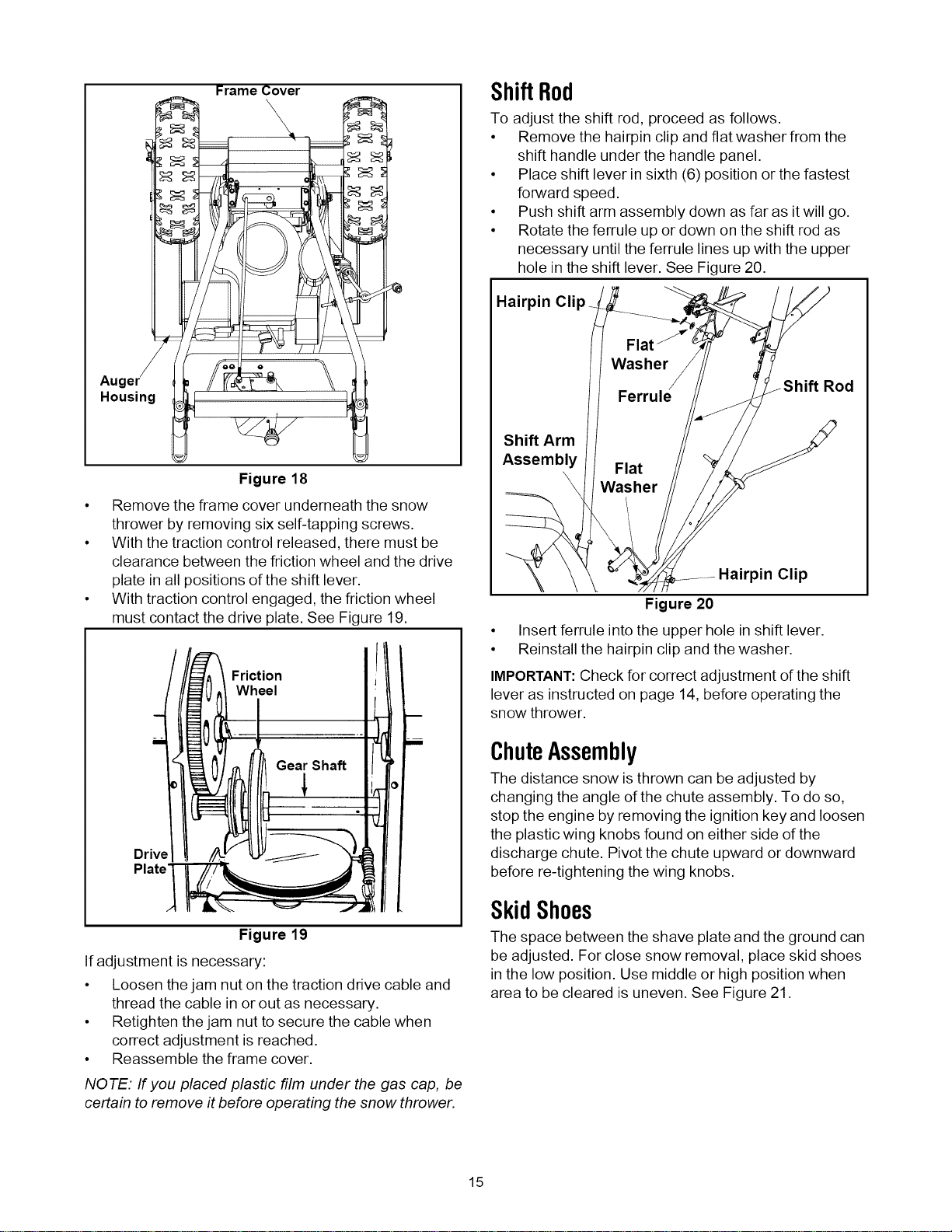
Frame Cover
Auger
Housing
Figure 18
• Remove the frame cover underneath the snow
thrower by removing six self-tapping screws.
• With the traction control released, there must be
clearance between the friction wheel and the drive
plate in all positions of the shift lever.
• With traction control engaged, the friction wheel
must contact the drive plate. See Figure 19.
Friction
Wheel
Gear Shaft
Driv_
Plate'_
Figure 19
If adjustment is necessary:
• Loosen the jam nut on the traction drive cable and
thread the cable in or out as necessary.
• Retighten the jam nut to secure the cable when
correct adjustment is reached.
• Reassemble the frame cover.
NOTE: If you placed plastic film under the gas cap, be
certain to remove it before operating the snow thrower.
ShiftRod
To adjust the shift rod, proceed as follows.
• Remove the hairpin clip and flat washer from the
shift handle under the handle panel.
• Place shift lever in sixth (6) position or the fastest
forward speed.
• Push shift arm assembly down as far as it will go.
• Rotate the ferrule up or down on the shift rod as
necessary until the ferrule lines up with the upper
hole in the shift lever. See Figure 20.
Hairpin Clip
_Shift Rod
Shift Arm
Assembly
Clip
Figure 20
• Insert ferrule into the upper hole in shift lever.
• Reinstall the hairpin clip and the washer.
IMPORTANT:Check for correct adjustment of the shift
lever as instructed on page 14, before operating the
snow thrower.
ChuteAssembly
The distance snow is thrown can be adjusted by
changing the angle of the chute assembly. To do so,
stop the engine by removing the ignition key and loosen
the plastic wing knobs found on either side of the
discharge chute. Pivot the chute upward or downward
before re-tightening the wing knobs.
SkidShoes
The space between the shave plate and the ground can
be adjusted. For close snow removal, place skid shoes
in the low position. Use middle or high position when
area to be cleared is uneven. See Figure 21.
15
Loading ...
Loading ...
Loading ...