®
Gourmet
Freestanding Range
Gas Cooktop
Electric Oven
User Manual
&
Installation Instructions
IMPORTANT SAFETY INSTRUCTIONS
Carefully read the important information
regarding installation, safety and maintenance.
Keep these instructions for future reference.
— 2 —
INSTALLERS - Start Here
Safety Instructions are on pages 4 to 10 and
Installation Instructions are on pages 11 to 23.
Please perform these steps:
1. Read the safety instructions.
2. Read all instructions in the Installation section of this
manual BEFORE installing the range.
3. Remove all packing materials from the oven before
connecting the gas supply.
4. Observe all governing codes and ordinances.
5. When nished, make sure to leave these instructions with the consumer.
6. Installation is only to be done by a qualied technician, but ultimately proper
installation is the responsibility of the installer.
7. Product failure due to improper installation is not covered under the Warranty.
CONSUMERS - Start Here
Safety Instructions are on pages 24 to 26 and
Operating Instructions are on pages 27 to 33.
Please perform these steps:
1. Read the safety instructions.
2. Read all instructions in the manual BEFORE
operating the range.
3. Remove all packing materials from the oven before using.
4. Observe all governing codes and ordinances.
5. Installation is only to be done by a qualied technician, but ultimately proper
installation is the responsibility of the installer.
6. Product failure due to improper installation is not covered under the Warranty.
Before You Begin

— 3 —
Before You Begin ..................................................................................................................................... 2
Table of Contents
.................................................................................................................................... 3
Important Safety Information
.................................................................................................................. 4
Installation
............................................................................................................................................. 11
Pipe Selection ................................................................................................................................. 11
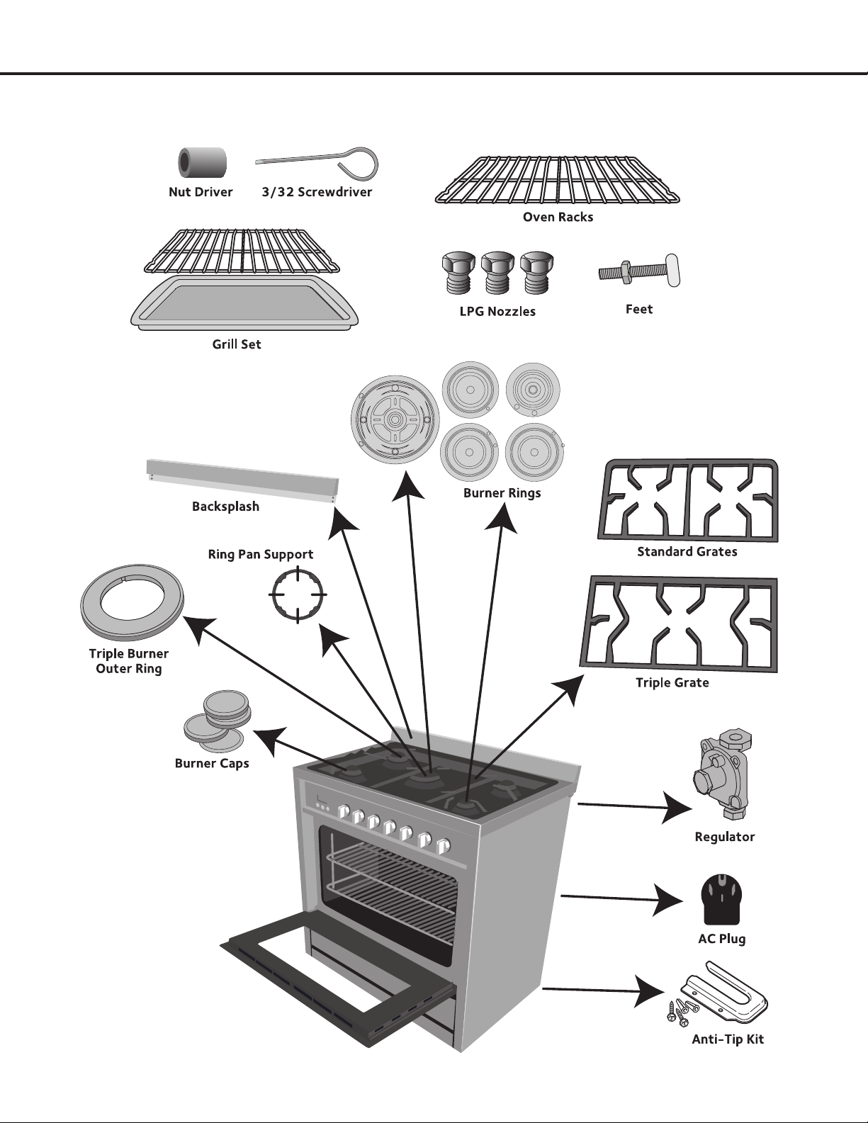
Included Parts ................................................................................................................................. 12
Tools and Additional Parts Needed ................................................................................................. 13
Range Dimensions .......................................................................................................................... 14
Step 1 - Read the Safety Precautions ............................................................................................. 15
Step 2 - Plan Desired Location, Unpack the Range and Prepare Tools ......................................... 15
Step 3 - Install Leveling Feet and Back Splash .............................................................................. 15
Step 4 - Gas Connection ................................................................................................................ 16
Step 5 - Liqueed Petroleum (Propane) Gas Conversion ............................................................... 18
Adjusting the Regulator Pressure ...................................................................................... 18
Changing Burner Nozzles .................................................................................................. 19
Adjusting the Burner Flames ............................................................................................. 19
Testing Flame Stability ....................................................................................................... 20
Electrical Specications ..................................................................................................... 20
Step 6 - Install Anti-Tip Bracket ...................................................................................................... 21
Step 7 - Burner Rings and Caps Placement ................................................................................... 22
Step 8 - Connect to AC................................................................................................................... 23
Safety Before Operating
........................................................................................................................ 24
Operation
............................................................................................................................................... 27
Location of Controls ........................................................................................................................ 27
Setting the Clock............................................................................................................................. 28
Setting the Timer ............................................................................................................................. 28
Oven Timed Cooking ...................................................................................................................... 28
Burners and Cookware ................................................................................................................... 29
Burner Cooking ............................................................................................................................... 30
Oven Racks ..................................................................................................................................... 30
Oven Controls ................................................................................................................................. 31
Oven Cooking Modes ..................................................................................................................... 31
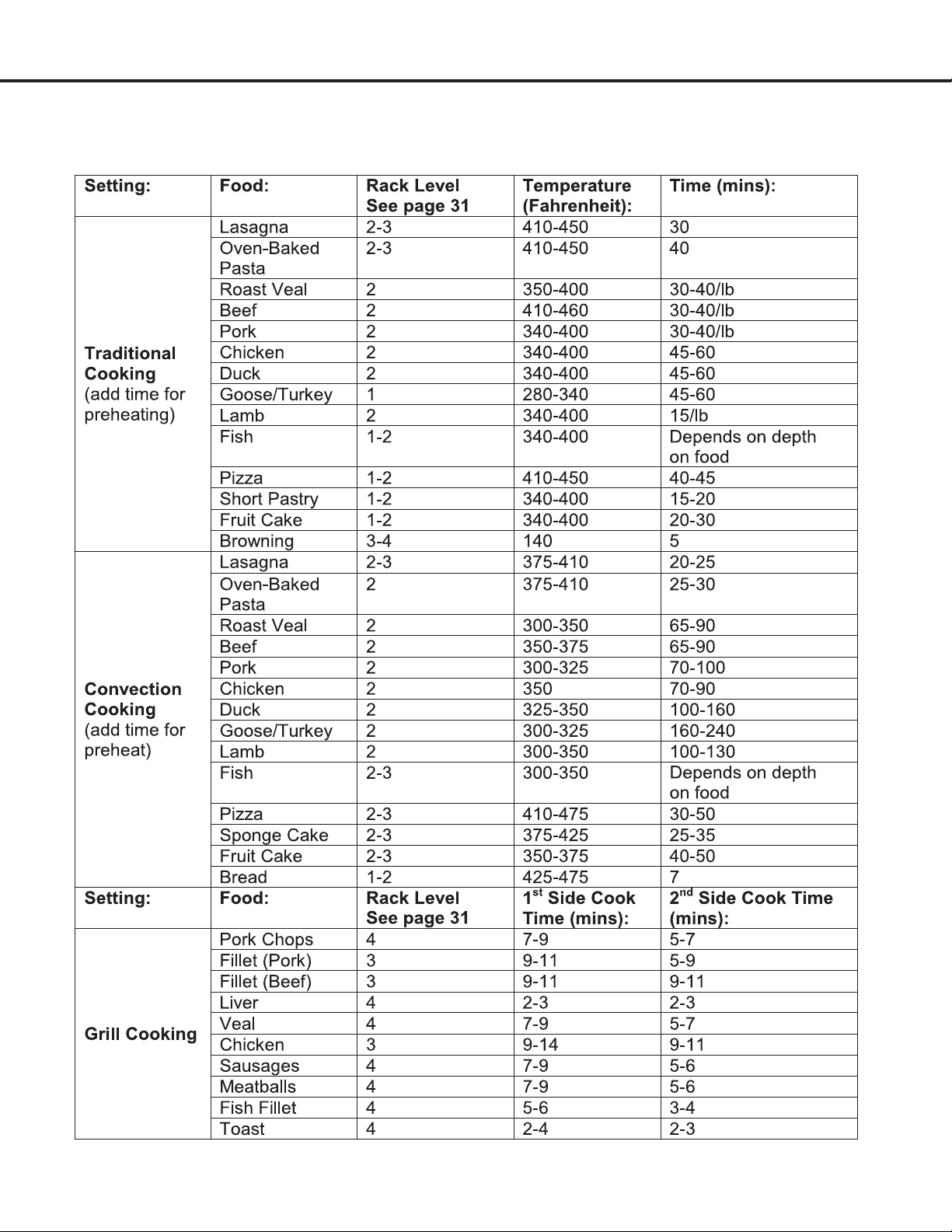
Cooking Chart ................................................................................................................................. 33
Care and Maintenance
.......................................................................................................................... 34
Removing the Oven Door ................................................................................................................ 35
Replacing the Light Bulb ................................................................................................................. 36
Adjusting the Burner Flames ........................................................................................................... 36
Before Calling for Service
...................................................................................................................... 37
Table of Contents
— 4 —
Important Safety Information
READ ALL INSTRUCTIONS BEFORE USE
Read and follow all instructions before using your oven to prevent the risk of re, electric shock, personal
injury, or damage when using the range. This guide does not cover all possible conditions that may occur.
Always contact your service technician or manufacturer about problems that you do not understand.
DANGER: When you see this symbol in the instructions, it indicates a hazardous
situation which, if not avoided, could result in death or serious injury.
WARNING: When you see this symbol in the instructions, it indicates a hazardous
situation which, if not avoided, could result in minor or moderate injury.
WHAT TO DO IF YOU SMELL GAS
•Openallwindowsstartingwiththoseclosesttotherange.
•DONOTtrytolightanyappliance.
•DONOTtouchanyelectricalswitchoroutlet.
•DONOTuseanyphoneinyourhome/building.
•Immediatelycallyourgassupplierfromaneighbor’sphone.Followthegassupplier’sinstructions.
•Ifyoucannotreachyourgassupplier,calltheredepartment.
INSTALLATION
•Removealltapeandpackagingbeforeusingtheappliance.Neverallowchildrentoplaywithpackagingmaterial.
•Donotremovethemodel/serialplateattachedtotheappliance.
•BesureyourapplianceisproperlyinstalledandgroundedbyaQUALIFIEDTECHNICIANinaccordancewithalllocal
codes and ordinances and with the National Fuel Gas Code ANSI Z223.1—latest edition and the National Electrical
CodeANSI/NFPANo.70—latesteditioninUnitedStates,orCAN/CGAB149.1,B149.2,andtheCanadianElectrical
Code, Part 1, in Canada.

— 5 —
Important Safety Information
WARNINGS
•Donotstoreorusegasolineorotherammablevapors
and liquids in the vicinity of this or any other appliance.
•Gasleakscannotalwaysbedetectedbysmell.
•Gassuppliersrecommendthatyouuseagasdetector
approved by UL or CSA. For more information, contact
your gas supplier.
•Ifagasleakisdetected,followthe“Whattodoifyou
smell gas” instructions on the previous page.
•Installationandservicemustbeperformedbyaqualied
installer, servicer or the gas supplier. Ask your dealer
to recommend a qualied technician and an authorized
repair service. Know how to shut off gas supply at
the meter and disconnect the electrical power to the
appliance at the circuit breaker or fuse box in case of an
emergency. Have the installer show you the location of
the range gas shut-off valve and how to shut it off
if necessary.
•Donotrepairorreplaceanypartoftheapplianceunless
specically recommended in this manual. All other
servicing should be done only by a qualied technician.
This may reduce the risk of personal injury and damage
to the appliance.
•Proper Installation: The range, when installed, must
be electrically grounded in accordance with local codes
or, in the absence of local codes, with the National
ElectricalCode,ANSI/NFPA70.InCanada,therange
must be electrically grounded in accordance with
Canadian Electrical Code. Be sure the range is properly
installed and grounded by a qualied technician.
•Disconnectpowerbeforeservicing.
•Nevermodifyoraltertheconstructionoftheappliance
by removing panels, wire covers or any other part of
the product.
•Injuriesmayresultfromthemisuseofappliancedoors
or drawers such as stepping, leaning, or sitting on the
doors or drawers.
•Overheadrangehoods,whichoperatebyblowinga
downwardairowontoarange,shallnotbeusedin
conjunction with gas ranges other than when the hood
and range have been designed, tested and listed by an
independent test laboratory for use in combination with
each other.
•Ifrangeislocatednearawindow,NEVERhanglong
curtains or paper blinds on that window. They could
blow over the surface burners and ignite, causing a
re hazard.
•Ensurethattheroomiswellventilatedbykeepingtheair
intakes open and in good working order or by installing
an extractor hood with discharge pipe. If the appliance
is used intensively for a long time the effectiveness of
the ventilation will have to be increased, for example
by opening a window or increasing the power of any
electric extractor fan.
•Flammablematerialsshouldnotbestoredonthe
appliance or near surface units. This includes paper,
plastic and cloth items, such as cookbooks, plastic
wareandtowels,aswellasammableliquids.Donot
store explosives, such as aerosol cans, on or near the
appliance. Flammable materials may explode and result
in re or property damage.
•Maintenance: Keep range area clear and free from
combustiblematerials,gasoline,andotherammable
vapors and liquids.
•Storage in or on the Range: Flammable materials
should not be stored in an oven or near surface units.
IN THE STATE OF MASSACHUSETTS, THE FOLLOWING
INSTALLATION INSTRUCTIONS APPLY:
•Installationsandrepairsmustbeperformedbya
qualied or licensed contractor, plumber, or gas-tter
qualied or licensed by the State of Massachusetts.
•Ifusingaballvalve,itshallbeaT-handletype.
•Aexiblegasconnector,whenused,mustnotexceed
three feet.
STATE OF CALIFORNIA PROPOSITION 65 WARNINGS:
•TheCaliforniaSafeDrinkingWaterandToxic
Enforcement Act requires the Governor of California to
publish a list of substances known to the state to cause
birth defects or other reproductive harm and requires
businesses to warn customers of potential exposure to
such substances.
•Gasappliancescancauseminorexposuretothree
of these substances, namely, carbon monoxide,
formaldehyde and soot, caused primarily by the
incomplete combustion of natural gas or LP fuels.
Properly adjusted burners, indicated by a bluish rather
thanyellowame,willminimizeincompletecombustion.
Exposure to these substances can be minimized by
venting with an open window or by using a ventilation
fan or hood.

— 6 —
Important Safety Information
DANGER
•Donotstoreitemsofinteresttochildreninthecabinets
above the appliance or on the back splash of a range.
Children should not be left alone or unattended in the
area where appliance is in use. Do not allow children to
climb or play around the appliance. They should never
be allowed to sit or stand on any part of the appliance.
Children climbing on the appliance to reach items could
be seriously injured.
•DONOTTOUCHTHECOOKINGSURFACE,THE
BURNERS,GRATES,ORANYAREASNEARTHEM.
Surface burners or appliance may be hot even though
amesarenotvisible.Areasnearsurfaceburnersor
appliance may become hot enough to cause burns.
During and after use, do not touch, or let clothing or
otherammablematerialstouchtheseareasuntilthey
have had sufcient time to cool.
•Donotwearloose-ttingorhanginggarmentswhile
using the appliance. Do not let clothing or other
ammablematerialscontacthotsurfaces.
•Smothergreasereswithapanlid,orusebakingsoda,
a dry chemical or foam-type extinguisher.
•UseanextinguisherONLYif:
- You know you have a Class A, B or C extinguisher, and
you already know how to operate it.
- The re is small and contained in the area where it
is started.
-Theredepartmentisbeing/hasbeencalled.
- You can ght the re with your back to an exit.
•Whenheatingfatorgrease,watchitclosely.Fator
grease may catch re if allowed to become too hot.
•Useonlydrypotholders.Moistordamppotholderson
hot surfaces may result in burns from steam. Do not
letpotholderstouchhotheatingelements,theameor
burners. Do not use a towel or other bulky cloth instead
of a potholder.
•Donotheatunopenedfoodcontainers.Buildupof
pressure may cause the container to burst and result
in injury.
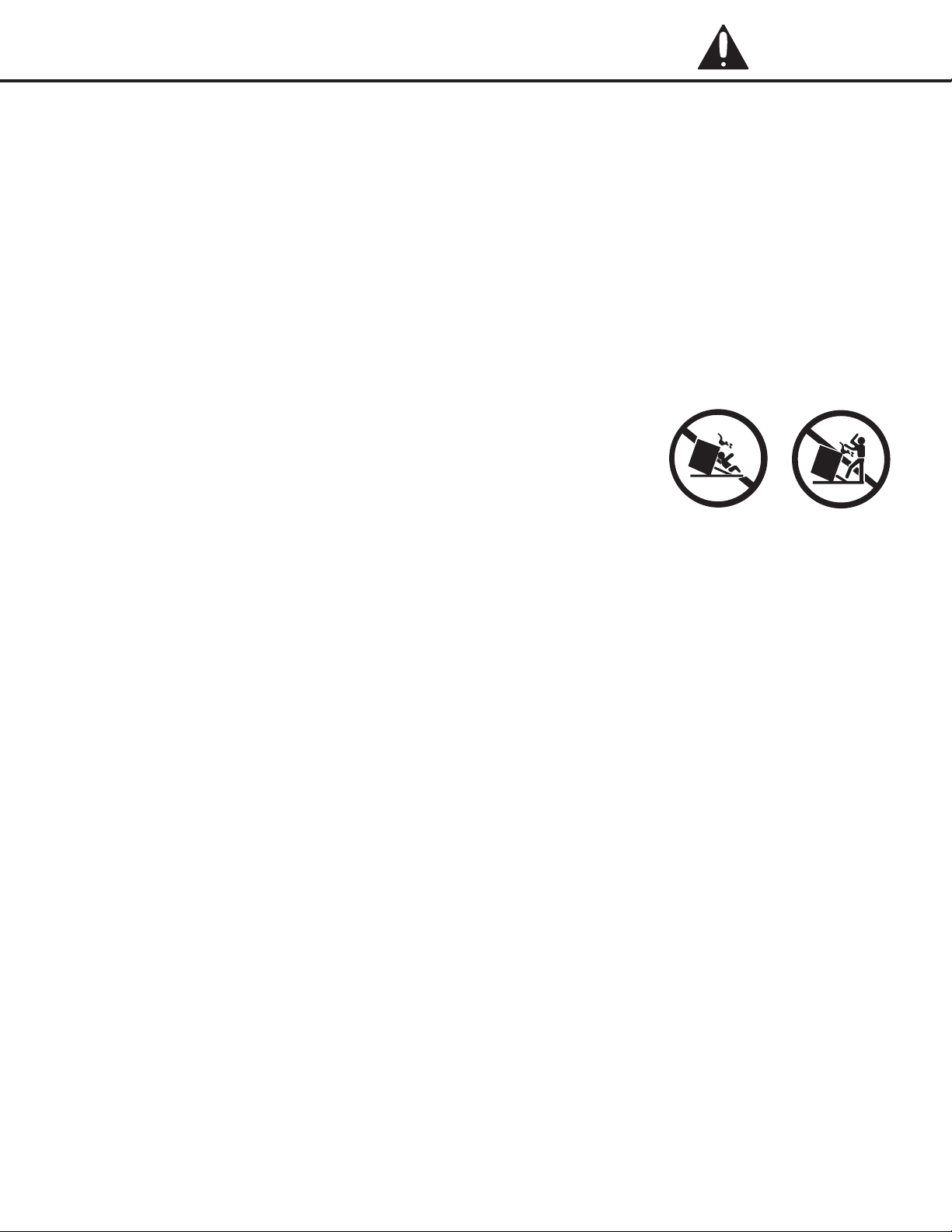
•Stepping,leaningorsittingonthisappliancecanresultin
serious injuries and also cause damage to the appliance.
•Neverusethisapplianceasaspaceheatertoheator
warm the room. Doing so may result in carbon monoxide
poisoning and overheating of the oven.
•Knowwhichknobcontrolswhichsurfaceburner.Visually
checkthattheburnerhaslit.Thenadjusttheamesoit
doesnotextendbeyondtheedgeofthepot/pan.
•Cleantheapplianceregularlytokeepallpartsfreeof
grease that could catch re. Exhaust fan ventilation
hoods and grease lters should be kept clean. Do not
allow grease to accumulate on hood or lter. Greasy
deposits in the fan could catch re. When cooking food,
turnthehoodfanon.Refertohoodmanufacturer’s
instructions for cleaning.
•
Pot/panhandlesshouldbeturnedinwardandnot
extend over adjacent surface burners. To reduce the
riskofburns,ignitionofammablematerials,and
spillageduetounintentionalcontactwiththepot/pan,
the handle of the utensil should be positioned so that
it is turned inward, and does not extend over adjacent
surface burners.
•Neverleavesurfaceburnersunattendedathighheat
settings. Boilovers cause smoke and greasy spillovers
that may ignite, or a pan that has boiled dry may melt.
•Donotusealuminumfoiltolineanypartofthe
appliance. Use aluminum foil only to cover food during
cooking. Improper installation of these liners may result
in risk of electric shock or re.
•Onlycertaintypesofglass,glass/ceramic,ceramic,
earthenware, or other glazed utensils are suitable for
appliance service without breaking due to the sudden
changeintemperature.Checkthemanufacturer’s
recommendations for appliance use.
•Donotusedecorativesurfaceburnercovers.Ifa
burner is accidentally turned on, the decorative cover
will become hot and possibly melt. You will not be able
to see that the burner is on. Burns will occur if the hot
covers are touched. Damage may also be done to
the range or burners because the covers may cause
overheating. Air will be blocked from the burner and
cause combustion problems.
•Alwaysuseproperamesize.Adjustamesizesoit
doesnotextendbeyondtheedgeofthepot/pan.The
useofundersizedpots/panswillexposeaportionofthe
burnerametodirectcontactandmayresultinignition
ofclothing.Properrelationshipofpot/pantoamewill
also improve efciency.
•Topburneramesizeshouldbeadjustedsoitdoesnot
extend beyond the edge of the cooking utensil.
— 7 —
Important Safety Information
DANGER
•Usetheproperpot/pansizes.Thisapplianceis
equipped with surface units of different sizes. Select
pots/panshavingatbottomslargeenoughtocoverthe
surface unit. The use of undersized utensils will expose a
portion of the surface heating unit to direct contact and
may result in ignition of clothing. Proper relationship of
utensil to the surface unit will also improve efciency.
•Donotusestovetopgrillsonyourgasappliance.Ifyou
use a stove top grill on a sealed gas burner, it will cause
incomplete combustion and can result in exposure
to carbon monoxide levels above allowable current
standards. This can be hazardous to your health.
•Removeallpackagingmaterialsfromtherangebefore
operating it. These materials can ignite, causing smoke
and/orredamage.
TIPPING DANGER
•TIPPINGRANGESCANCAUSESERIOUSPERSONALINJURYORDEATH.
•TOREDUCETHERISKOFTIPPINGOFTHERANGE,THERANGEMUSTBE
SECUREDWITHAPROPERLYINSTALLEDANTI-TIPDEVICE.
•FAILURETOPROPERLYINSTALLTHEANTI-TIPBRACKETCOULDRESULTIN
THEDEATHOFACHILDORADULT.
•Tocheckifthedevicehasbeenproperlyinstalled,sliderangeforward,lookforanti-tipbracketsecurelyattachedtooor
or wall then slide range back so rear range foot is under anti-tip bracket.
•Carefullypullontherangefromtherear.Ifthebracketisinstalledcorrectly,therangewillnottipmorethan4inchesfrom
the wall. If it tips forward more than 4 inches, the anti-tip device has not been has not been installed correctly.
•CAUTION:DONOTTIPTHERANGEMORETHAN4INCHESFROMTHEWALLASITCOULDTIPOVERANDCAUSE
INJURY.
•Iftherangeispulledfromthewallforanyreason,alwaysrepeatthisproceduretoverifytherangeisproperlysecured
by the anti-tip bracket.
•Nevercompletelyremovethelevelinglegsortherangewillnotbesecuredtotheanti-tipdeviceproperly.
•NEVERsteporsitonthedoor.
•Therangewillnottipduringnormaluse.However,withoutaproperlyfastenedanti-tipbracket,therangecantipiftoo
much force or weight is applied to the open door.
•Seepage21forinstructionsonhowtoinstalltheAnti-TipBracket.
— 8 —
Important Safety Information
VENTILATION WARNINGS
•Therangeshouldhaveproperventilationinorderto
keep the unit operating properly and maintain the
temperature of immediate surroundings within safe
limits. Check your local building codes as they may vary
from the general rules outlined in this guide.
•Observeallgoverningcodesandordinances.Donot
obstructowofcombustionandventilationair.
•Itistheinstaller’sresponsibilitytocomplywith
installationclearancesspeciedonthemodel/serial
rating plate.
•Forproperoperationofagasappliance,theair
necessary for the combustion of the gas must be able
toowintotheroomnaturally.Theairmustowinto
the room directly through openings in the outside walls.
These openings must have an unobstructed cross-
sectionnotlessthan2m3/hforeachkwofpower(see
total power in kw on the appliance).
•Thisopeningmustbeconstructedsothatitwill
not be obstructed from inside or outside, and not
beconstructedclosetotheoor.Theopeningis
recommended to be on the side opposite to that on
whichtheuegasesaredischarged.
•
The range should be located for convenient use in
the kitchen.
•Recessedinstallationsmustprovidecompleteenclosure
of the sides and rear of the range.
•Toeliminatetheriskofburnsorrebyreaching
overheated surface units, cabinet storage space located
above the surface units should be avoided. If cabinet
storage is to be provided, the risk can be reduced by
installing a range hood or microwave hood combination
with minimum 400 CFM that projects horizontally a
minimum of 5” (12.7 cm) beyond the bottom of
the cabinets.
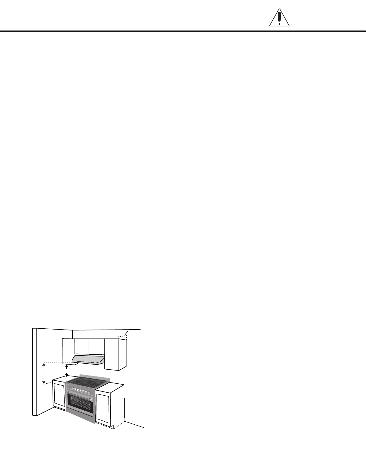
•Ifarangehoodisinstalledabovetheappliance,
maintain a 30” minimum clearance between cooking
surface and bottom of range hood. The range hood
mustbeconnecteddirectlytouesortotheoutside.
•Avoidplacingcabinetrydirectlyabovetheappliance
when possible. If cabinetry is used above the cooking
surface, use cabinets no more than 13” deep. Make
sure the wall coverings, countertop and cabinets around
the appliance can withstand heat up to 200º F (93°C)
generated by the appliance.
•Cabinetopeningdimensionsthatareshownmustbe
used. Given dimensions are minimum clearances.
•
Working areas adjacent to the range should have
18” minimum clearance between countertop and
cabinet bottom. (See Figure 1)
•Allopeningsinthewalloroorwhererangeistobe
installed must be sealed.
•Contactaqualiedoorcoveringinstallertocheckthat
theoorcoveringcanwithstandatleast200°F(93°C).
•Useaninsulatedpador1/4”(0.64cm)plywoodunder
range if installing range over carpeting.
•Theooranti-tipbracketmustbeinstalled.Toinstallthe
anti-tipbracketshippedwiththerange,see“InstallAnti-
Tip Bracket” section on page 21.
•Groundedelectricalsupplyisrequired.See“Connect
to AC” section on page 23, as well as the safety
precautions on page 10.
•Propergassupplyconnectionmustbeavailable.See
“GasConnection”sectiononpages16and17,aswell
as the safety precautions on page 9.
30”(76.2 cm)
Min.
18” (45.7 cm) Min.
13” (33 cm) Max.
Figure 1
— 9 —
Important Safety Information
INSTALLATION WARNINGS
To avoid damage to your cabinets, check with
your builder or cabinet supplier to make sure that
the materials used will not discolor, delaminate or
sustain other damage. This oven has been designed
in accordance with the requirements of UL and CSA
International and complies with the maximum allowable
wood cabinet temperatures of 194°F (90°C).
MOBILE HOME – ADDITIONAL INSTALLATION
REQUIREMENTS:
The installation of this range must conform to the
ManufacturedHomeConstructionandSafetyStandard,
Title 24 CFR, Part 3280 (formerly the Federal Standard
forMobileHomeConstructionandSafety,Title24,HUD
Part 280).
When such standard is not applicable, use the Standard
forManufacturedHomeInstallations,ANSIA225.1/NFPA
501A or with local codes.
In Canada, the installation of this range must conform
withthecurrentstandardsCAN/CSA-A240-latest
edition, or with local codes.
MOBILE HOME INSTALLATIONS REQUIRE:
When this range is installed in a mobile home, it must
besecuredtotheoorduringtransit.Anymethodof
securing the range is adequate as long as it conforms to
the standards listed above.
GAS DANGER
Explosion hazard conditions will exist unless
you perform ALL of the following:
•UseanewCSAInternationalapprovedgas
supply line.
•Installashut-offvalve.
•Securelytightenallgasconnections.
•IfconnectedtoLP,haveaqualiedpersonmakesure
gas pressure does not exceed 14” (36 cm) water column.
•Examplesofaqualiedpersoninclude:
- Licensed heating personnel
- Authorized gas company personnel
- Authorized service personnel
Failure to do so can result in death, explosion, or re.
•Observeallgoverningcodesandordinances.
IMPORTANT: This installation must conform with all
local codes and ordinances. In the absence of local
codes, installation must conform with American National
Standard, National Fuel Gas Code ANSI Z223.1 - latest
edition,orCAN/CGAB149-latestedition.
IMPORTANT: Leak testing of the range must be
conductedaccordingtothemanufacturer’sinstructions.
•Provideagassupplylineof3/4”(1.9cm)rigidpipetothe
range location. A smaller size pipe on longer runs may
result in insufcient gas supply. Pipe-joint compounds
that resist the action of LP gas must be used. Do not use
TEFLON® tape. With LP gas, piping or tubing size must
be1/2”(1.3cm)minimum.Usually,LPgassuppliers
determine the size and materials used in the system.
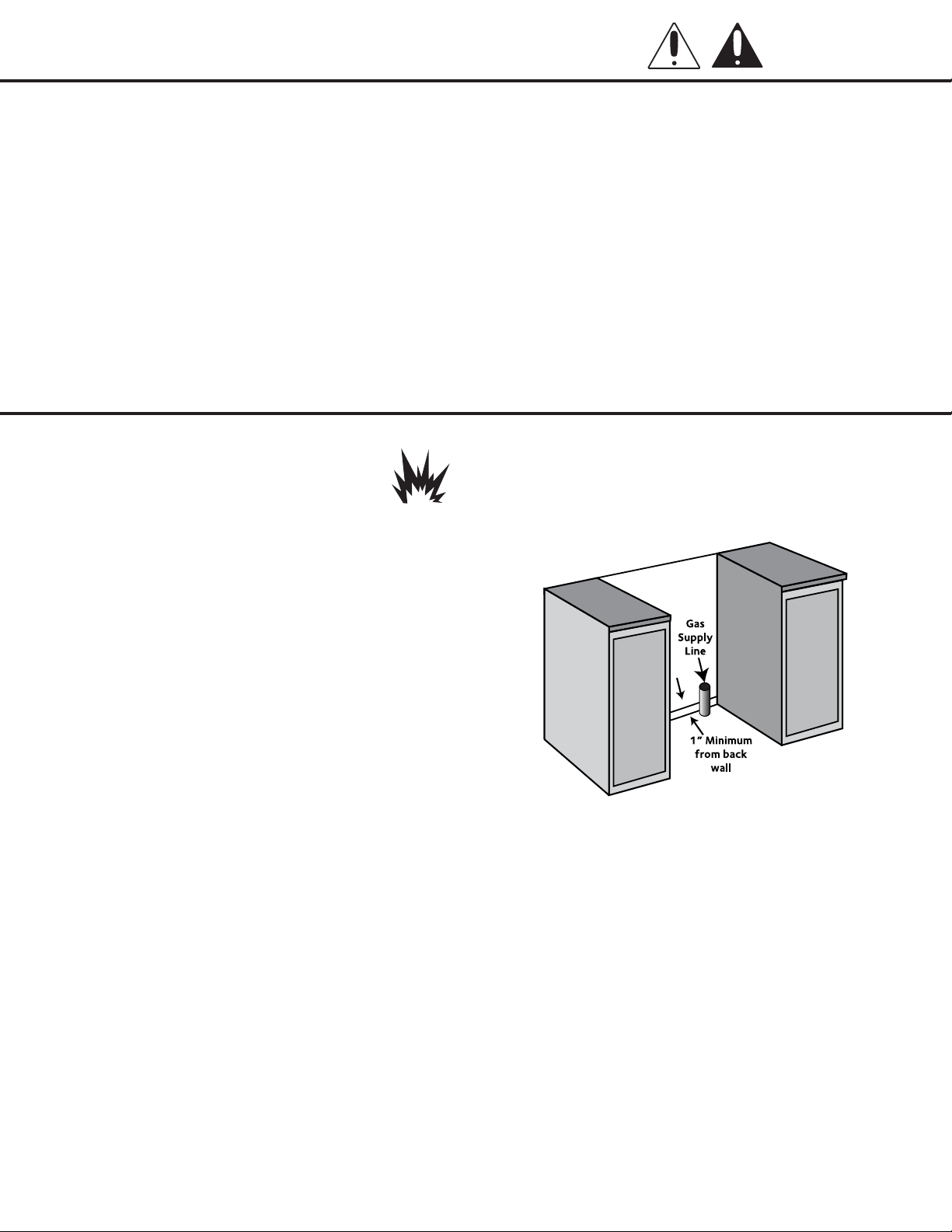
•Gassupplyshouldbelocatedneartheopeningforthis
appliance and be a minimum of 1” from the back wall
(See Figure 2):
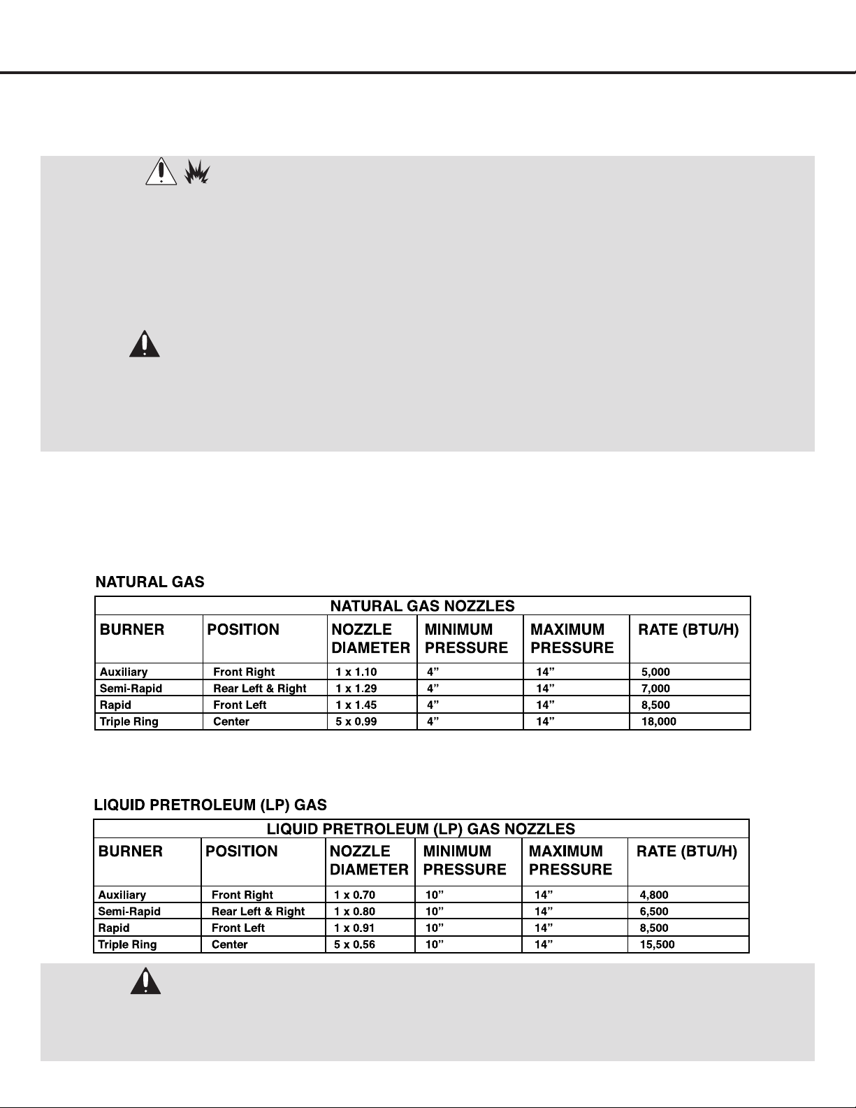
Types of Gas
NATURAL GAS:
•ThisrangeisdesignedforusewithNaturalgasor,after
proper conversion, for use with LP gas.
•ThisrangeisfactorysetforusewithNaturalgas.The
model/serialratingplatehasinformationonthetypes
of gas that can be used. If the types of gas listed do not
include the type of gas available, check with the local
gas supplier.
LP GAS CONVERSION:
•
Conversion must be done by a qualied service technician.
•Noattemptshallbemadetoconverttheappliancefrom
thegasspeciedonthemodel/serialratingplatefor
use with a different gas without consulting the serving
gas supplier.
Figure 2

— 10 —
Important Safety Information
ELECTRICAL DANGER
Electrical Shock Hazard.
Do not use an extension cord.
Failure to follow these instructions can result in death,
re, or electrical shock.
•Anyadditions,changesorconversionsrequiredinorder
for this appliance to satisfactorily meet the application
needs must be made by a qualied service technician
inaccordancewiththemanufacturer’sinstructions
and all codes and requirements of the authority having
jurisdiction. Failure to follow the instructions could
result in serious injury or property damage. The qualied
agency performing this work assumes responsibility for
the conversion.
•DONOToperatethisapplianceusinga2-prongadapter
or an extension cord. If a 2-prong wall receptacle is the
only available outlet, it is the personal responsibility
of the consumer to have it replaced with a properly
grounded 4-prong wall receptacle installed by a
qualied electrician.
•Severeshock,ordamagetotherangemayoccurifthe
range is not installed by a qualied installer or electrician.
•Thisappliancefeaturesapilot-lesselectricignitionfor
energysavingsandreliability.Itis220-240V/50-60Hz.
It is recommended to connect to a 50 Amp power
supply.
•TotalInputPoweris3.5kw(14.59A).Adedicatedcircuit,
protected by a minimum 15 to 30 amp time delay fuse
or circuit breaker is required.
•Forpersonalsafety,theappliancemustbe
properly grounded.
— 11 —
Installation
OPTION 1: FLEXIBLE METAL APPLIANCE CONNECTOR:
•Neverreuseoldexibleconnectors.Theuseofold
exibleconnectorscancausegasleakageandpersonal
injury.Alwaysusenewexibleconnectorswheninstalling
a gas appliance. To reduce the possibility of gas leakage,
applyTeontapeorathreadcompoundapprovedforuse
with LP or Natural gases to all threaded connections.
•
If local codes permit, a new CSA design-certied, 4 to 5
ft(122to152.4cm)long,1/2”(1.3cm)or3/4”(1.9cm)
I.D.,exiblemetalapplianceconnectormaybeusedfor
connecting range to the gas supply line.
•
A1/2”(1.3cm)malepipethread/adapterisneededfor
connection to the female pipe threads of the inlet to the
appliance pressure regulator.
•Donotkinkordamagetheexiblemetaltubingwhen
moving the range.
OPTION 2: RIGID PIPE CONNECTOR:
•Therigidpipeconnectionrequiresacombinationofpipe
ttings to obtain an in-line connection to the range. The
rigid pipe must be level with the range connection. All
strains must be removed from the supply and fuel lines so
range will be level and in line.
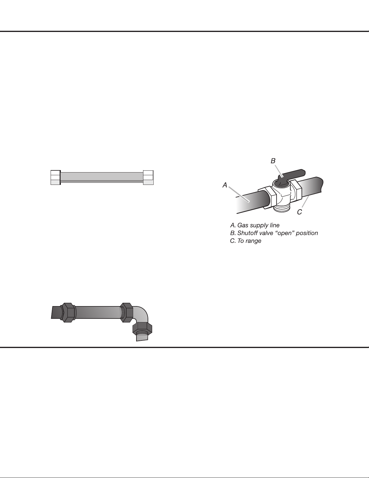
MUST INCLUDE A SHUT-OFF VALVE:
•Besureyouknowwhereandhowtoshutoffthegas
supply to the range.
•Thesupplylinemustbeequippedwithamanualshut-off
valve. This valve should be located in the same room but
external to the range in an easily accessible location. It
should be in a location that allows ease of opening and
closing. Do not block access to shut-off valve. The valve
is for turning on or shutting off gas to the range. (See
Figure 3)
Pipe Selection
BURNER INPUT REQUIREMENTS:
•Inputratingsshownonthemodel/serialratingplateare
for elevations up to 2,000 ft (609.6 m).
•Forelevationsabove2,000ft(609.6m),ratingsare
reduced at a rate of 4% for each 1,000 ft (304.8 m) above
sea level (not applicable for Canada).
GAS SUPPLY PRESSURE TESTING:
Line pressure testing above 1/2 psi gauge (14” WCP):
•Therangeanditsindividualshut-offvalvemustbe
disconnected from the gas supply piping system during
any pressure testing of that system at test pressures in
excessof1/2psi(3.5kPa).
Line pressure testing at 1/2 psi gauge (14” WCP) or lower:
•Therangemustbeisolatedfromthegassupplypiping
system by closing its individual manual shut-off valve during
any pressure testing of the gas supply piping system at test
pressuresequaltoorlessthan1/2psi(3.5kPa).
Figure 3
— 12 —
Installation
Included Parts
— 13 —
Installation
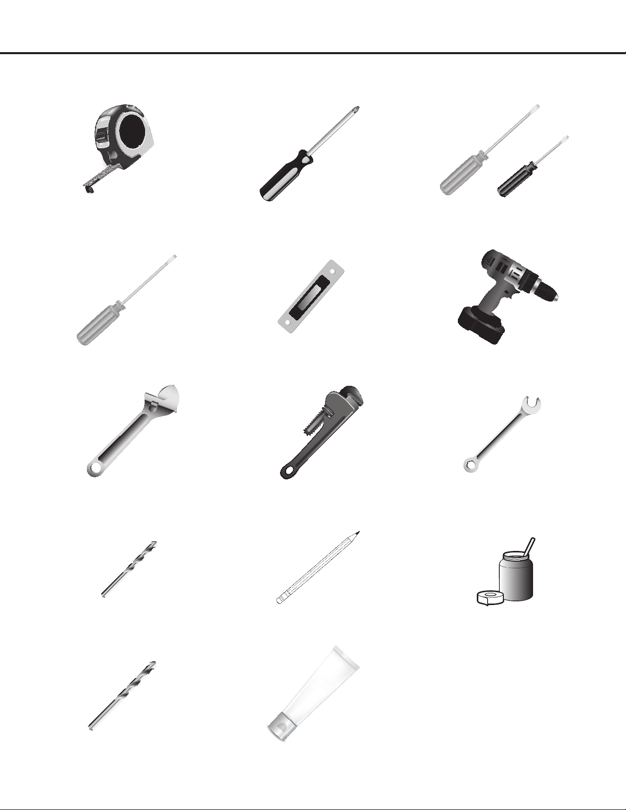
Tools and Additional Parts Needed
Tape measure Phillips screwdriver Flat blade screwdriver
1/8”atbladescrewdriver
HexscrewdriverLevel Handorelectricdrill
Wrench or pliers Pipe wrench 15/16”combinationwrench
1/8”(3.2mm)drillbit(forwoodoors)Marker or pencil
Pipe-joint compound resistant to
LP gas
3/16”(4.8mm)carbide-tippedmasonry
drillbit(forconcrete/ceramicoors)
Noncorrosive leak-detection solution
For Additional Parts:
Check local codes, consult gas
supplierandcheckexistinggas/
electricalsupply.See“Electrical
Requirements”and“GasSupply
Requirements” sections.
— 14 —
Installation
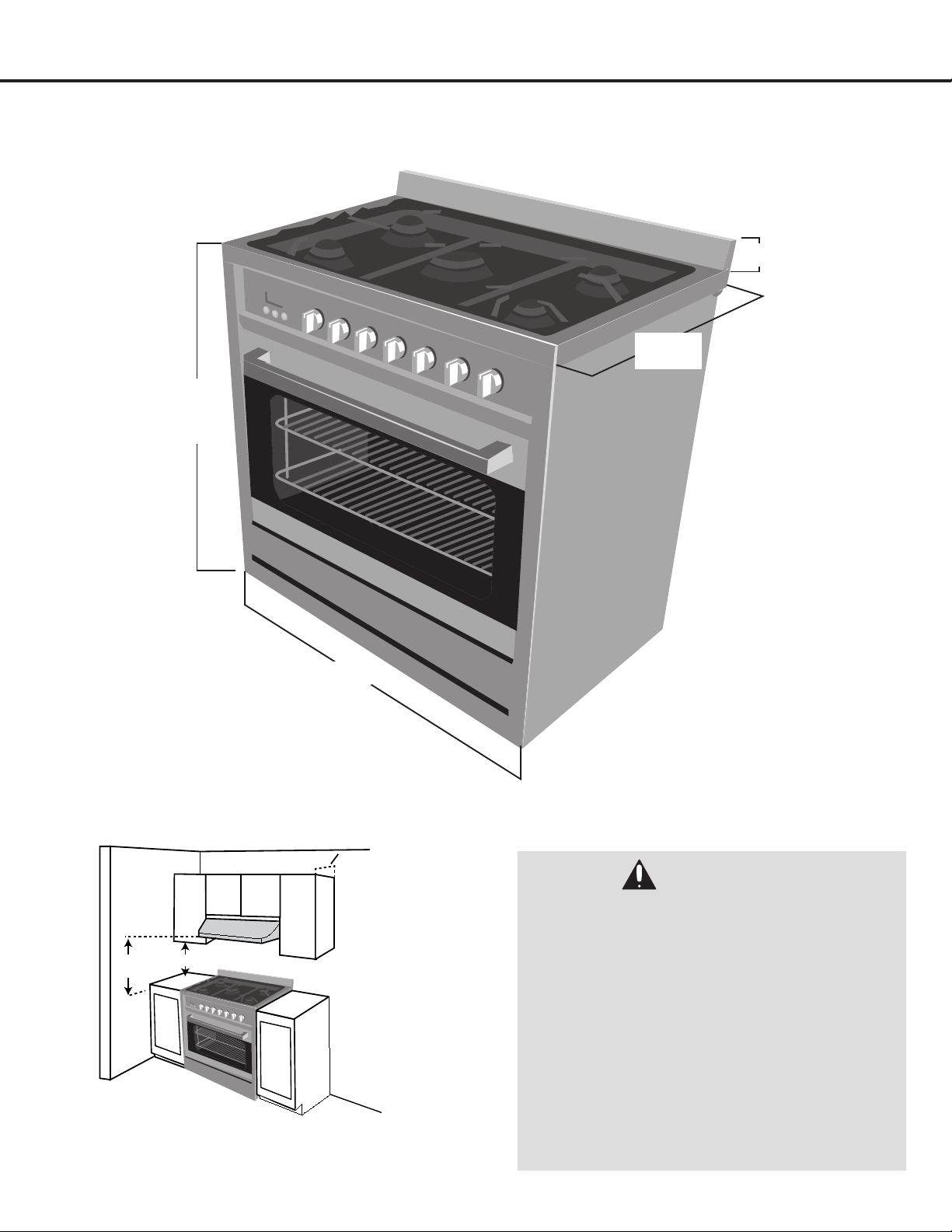
Range Dimensions
DANGER:
• Avoidplacingcabinetrydirectlyabovethe
appliance when possible. If cabinetry is used
above the cooking surface, use cabinets
no more than 13” deep. Make sure the wall
coverings, countertop and cabinets around
the appliance can withstand heat up to 200º
F (93°C) generated by the appliance.
• Cabinetopeningdimensionsthatare
shown must be used. Given dimensions are
minimum clearances.
• Workingareasadjacenttotherangeshould
have 18” minimum clearance between
countertop and cabinet bottom.
• SeeFigure4.
23 5/8”
(600mm)
2 3/8 “ (60 mm)
35 1/2 - 37 7/8”
(900 mm - 960 mm)
35 7/16“
(900 mm)
30”(76.2 cm)
Min.
18” (45.7 cm) Min.
13” (33 cm) Max.
Figure 4
— 15 —
Installation
STEP 1
Read the Safety Precautions
Please read the safety precautions on pages 4 to 10. Safety instructions pertaining to each step have been outlined in the
installation steps; however it is important to read ALL the safety instructions.
IMPORTANT: It is the installer’s responsibility to comply with installation clearances.
STEP 2
Plan Desired Location, Unpack the Range and Prepare Tools
Plan a desirable location that ts all requirements in the Safety and Install sections of this manual. Unpack the range and
parts carefully (including the parts contained in the oven cavity) and make sure all parts are included as shown on page 12.
Assemble all tools as shown on page 13. DO NOT remove the protective lm covering the appliance or remove the tape
securing the drawer.
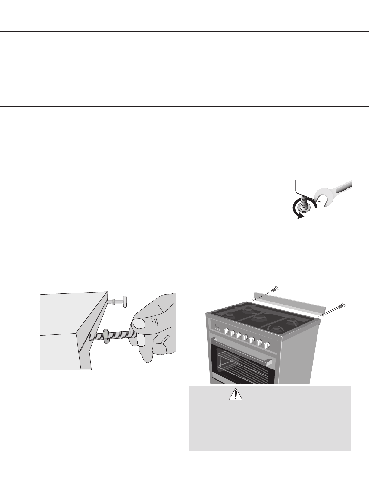
STEP 3
Install Leveling Feet and Back Splash
u
Remove the four L-shaped cardboard corner
protectors from the carton and stack them on top of
oneanother.Placethemontheoorandusingtwo
people, carefully lay the range on its back using the
cardboard corners to hold them up.
v
Install the leveling feet one at a time. (See Figure 5)
w
Placeaprotectorontheoorsuchasatcardboard
and using two people, stand the range upright onto
the protector.
x
Remove the protective lm covering the appliance
and the tape securing the drawer.
y
If range height adjustment
is necessary, use a wrench
to loosen the four leveling
feet and adjust as necessary,
using a level for best results.
If height adjustment is made
when range is standing,
tilt the range back to adjust the front legs, then tilt
forward to adjust the rear legs. (See Figure 6)
U
(Optional Step) Insert the stainless steel back splash
into the grooves on the top rear of the range then
secure using the hex screws. (See Figure 7)
WARNINGS:
• PleasemakesuretoreadALLsafetyprecautionson
pages 4 to 10.
• Usetwoormorepeopletomoveandinstallrange.
• Achildoradultcantiptherangeandbekilled.
• Failuretofollowtheseinstructionscanresultindeath
or serious burns to children and adults.
Figure 5
Figure 6
Figure 7
— 16 —
Installation
WARNINGS:
• PleasemakesuretoreadALLsafetyprecautionsonpages4to10.
• ExplosionHazard.
• UseanewCSAInternationalapprovedgassupplyline.
• Installashut-offvalve.
• Securelytightenallgasconnections.
• IfconnectedtoLP,haveaqualifiedpersonmakesuregaspressuredoesnotexceed14”(36cm)watercolumn.
Examples of a qualified person include: licensed heating personnel, authorized gas company personnel, and
authorized service personnel.
• Failuretodosocanresultindeath,explosion,orfire.
DANGER:
• ThisapplianceisoutfittedfromthefactorytobeusedwithONLYonetypeofgas.Thisrangeistobeconnectedwith
agassupplyline.Thegasconnectionisamale1/2”BSPandislocatedroughly2-1/4”fromthein from the right
hand side of the appliance and 22” from the ground. The hose must be free of kinks or other deformations that would
inhibit its ability to supply gas to the unit or cause a gas leak. Keep gas line s free from contact with any moving parts
such as a drawer to prevent damage or obstruction.
DANGER:
The gas supply line must be equipped with an approved manual shut-off valve. The shut-off valve must be in an
easily accessible location in the same room as the appliance. Do not block access to the shut-off valve. Be sure
you know how and where to shut off the gas supply to the range.
STEP 4
Gas Connection
u
INSTALL THE PRESSURE REGULATOR: This appliance is set for natural gas and is designed to operate at 5”
water column pressure. The gas supply is required to provide a minimum of 4” to a maximum of 14” water column
pressure to the appliance regulator. The pressure regulator must be connected in series with the manifold of the
appliance and must remain in series with the supply line regardless the type of gas being used.
For proper operation, the gas pressure regulator supplied with this range must be used. The inlet pressure to the
regulator should be as shown in the chart below.
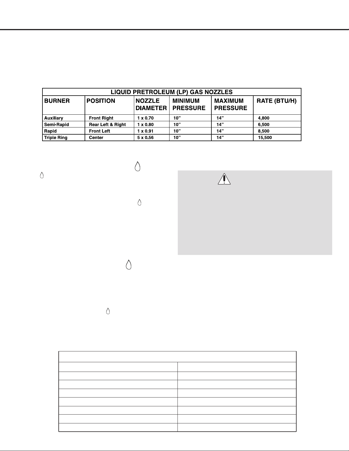
If the appliance is converted for liquid petroleum (LP) gas, the LP gas supply is required to provide a minimum of
10” to a maximum of 14” water column to the cooktop regulator.
— 17 —
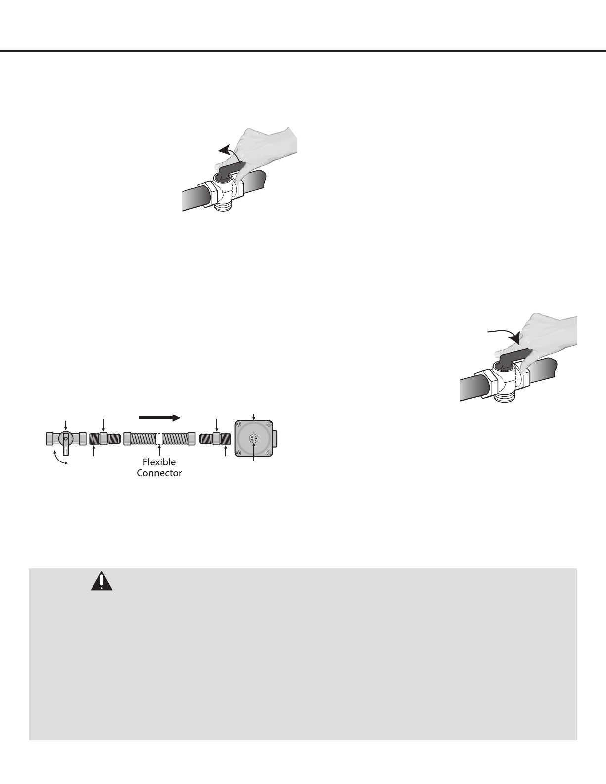
v
Shut off the gas supply
valve before removing
the old range and leave it
off until the new hook-up
has been completed. (See
Figure 8)
w The gas inlet is located 6” down from the top of the
applianceattherear,rightsideand2-1/2”infrom
the right hand side of the appliance. Make gas
connectionthroughrearwall,oroncabinetoorat
rear. Install the house gas supply at least 1” from the
back wall. Ensure a safety valve is tted at the end
of the pipeline.
x
The appliance leaves the factory tested and set for
natural gas. Make sure that the type of gas to be
supplied to the appliance is the same as that shown
on the label afxed to the rear of the appliance.
Pressure Regulator is marked with an arrow;
point this arrow towards the unit.
y
Attachoneadapter/areuniontothegaspressure
regulatorandtheotheradapter/areuniontothe
gas shut-off valve. Tighten both adapters. (See
Figure 9)
U
Attachtheexiblepipe(seepage11forpipe
selection) to the adapters (see gure above).
If metal hoses are used, make sure they do not
come into contact with mobile parts and are not
crushed. Make sure to use a pipe-joint compound
that is made for use with LP gas to the smaller
thread ends of the adapters.
The gas intake connection of the appliance has
a“malethread.”Whenmakingtheconnection,
take care not to apply stresses of any kind to the
appliance. Over- tightening may crack the regulator
resulting in a gas leak and possible re or explosion.
V
After connecting the
appliance to the gas
supply, make sure all
burners knobs are in
the OFF position. Once
regulator is in place, open
the shut-off valve in the
gas supply line. Wait a
few minutes for gas to
move through the
gas line. (See Figure 10)
W
Check the system for leaks with a manometer. If a
manometer is not available, turn on the gas supply
and use a liquid leak detector (or soap and water) at
all joints and connections to check for leaks.
Installation
STEP 4 (Continued)
Gas Connection
Joint Joint
Off
On
Manual
Shut off
Valve
Pressure
Regulator
Flare
Union
Flare
Union
Gas Flow
Access
Cap
DANGER:
• PleasemakesuretoreadALLsafetyprecautionsonpages4to10.
•
Do not use a flame to check for leaks from gas connections. Checking for leaks with a flame may result in a
fire or explosion.
• Tightenallconnectionsifnecessarytopreventgasleakageintherangeorsupplyline.
• Checkalignmentofcontrolknobvalvesafterconnectingtherangetothegassupplytobesuretherangemanifold
pipe has not moved. A misalignment could cause the valve stems to rub on the control panel, resulting in a gas leak
at the valve.
• Disconnectthisrangeanditsindividualmanualshut-offvalvefromthegassupplypipingsystemduringany
pressuretestingofthatsystemattestpressuresinexcessof1/2psi(3.5kPaor14”watercolumn).
•
Isolate the range from the gas supply piping system by closing its individual manual shut-off valve during any pressure
testingofthegassupplypipingsystemattestpressuresequaltoorlessthan1/2psi(3.5kPaor14”watercolumn).
Figure 8
Figure 9
Figure 10
— 18 —
Installation
STEP 5 (Optional)
(Must be done before Step 6 if converting to Propane)
Liqueed Petroleum (Propane)
Gas Conversion
ThisappliancecanbeusedwithNaturalGasorLP/Propane
Gas. It is shipped from the factory for use with Natural Gas. A
kit for converting to LP gas is supplied with your appliance.
Thekitismarked“FORLP/PROPANEGASCONVERSION”.
u
When the range is converted for Liquid Petroleum
(LP) Gas, the LP gas supply is required to provide a
minimum of 10” to a maximum of 14” water column
to the range regulator.
Following LP Gas
Conversion, complete
Steps2to14:“Adjusting
the Regulator Pressure”;
“ChangingBurner
Nozzles”;“Adjusting
Burner Flames”; and
“TestingFlameStability”
.
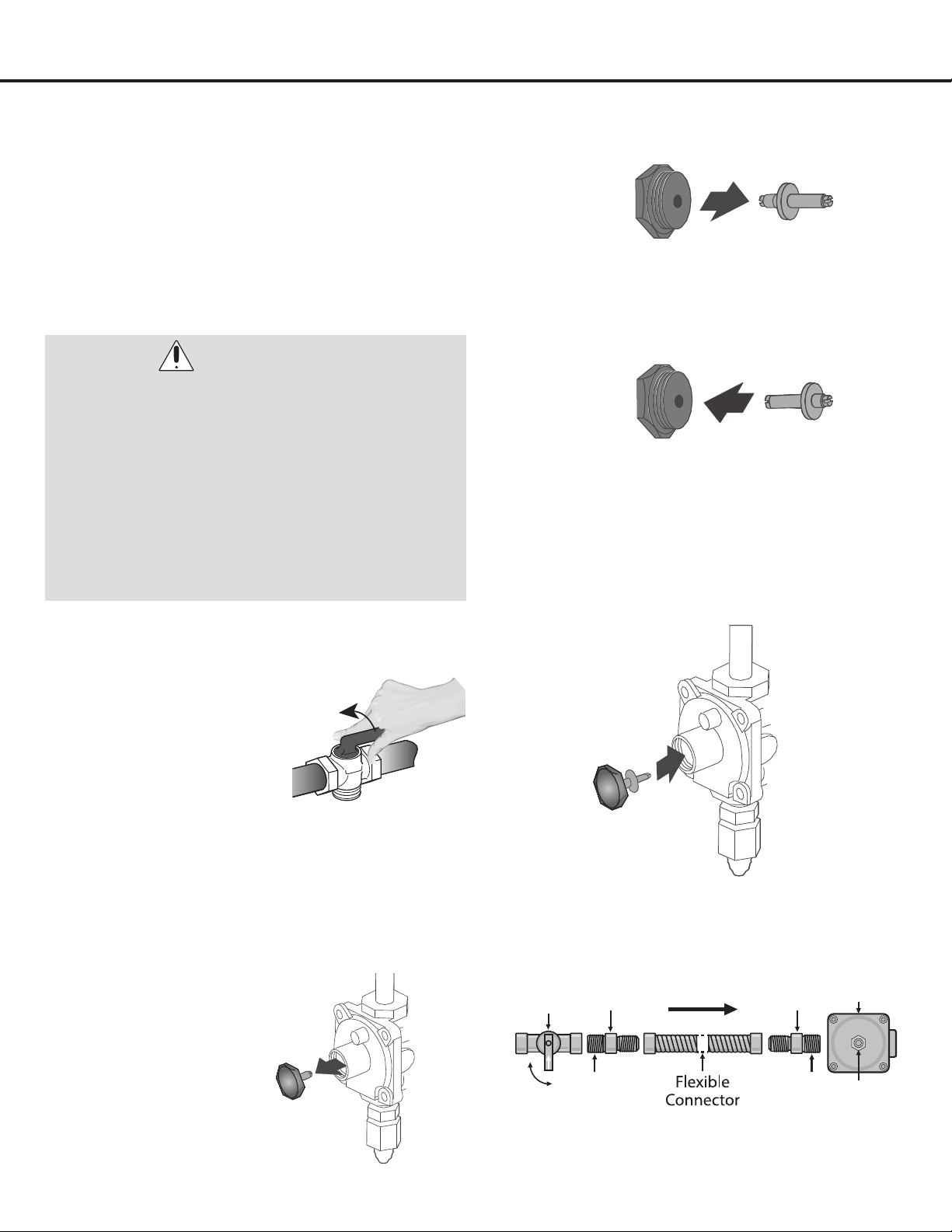
Adjusting the Regulator Pressure
v
Shut off the gas supply to the appliance by closing
the manual shut-off valve. (See Figure 11)
w
Unscrew the regulator
cap with a wrench.
(See Figure 12)
x
Remove retainer pin by pulling it out. (See Figure 13)
y
Reverse the retainer pin and snap it back into the
regulator cap. (See Figure 14)
U
Screw the regulator cap back into the regulator and
re-attachittothenippleandareunionasshown.
DO NOT over-tighten. (See Figures 15 and 16)
WARNINGS:
• PleasemakesuretoreadALLsafetyprecautionson
pages 4 to 10.
• Failuretomaketheappropriateconversionafter
Step 4 can result in serious personal injury and
property damage.
•
The conversion must be performed by a qualified
service technician in accordance with the kit instruc-
tions and all local codes and requirements. Failure
to follow instructions could result in serious injury or
property damage. The qualified agency performing this
work assumes responsibility for the conversion.
Joint Joint
Off
On
Manual
Shut off
Valve
Pressure
Regulator
Flare
Union
Flare
Union
Gas Flow
Access
Cap
Figure 11
Figure 12
Figure 15
Figure 16
Figure 13
Figure 14
— 19 —
Installation
STEP 5 (Continued)
Liqueed Petroleum (Propane)
Gas Conversion
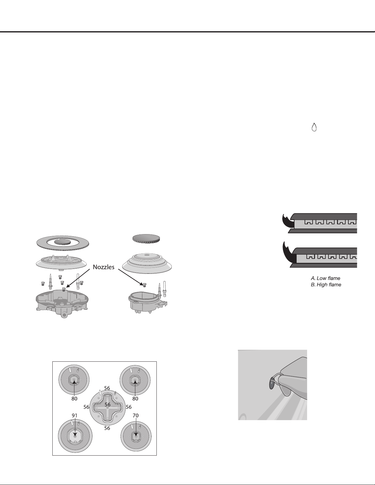
Changing Burner Nozzles
INSTALLATION TIP: To prevent any omissions,
remove ALL existing Natural Gas nozzles before
replacing them with the LP nozzles.
V
Remove the burner grates, burner caps and burner
rings. Using the provided 7mm nut driver, remove
ALL the existing Natural Gas burner nozzles.
Carefully read and observe each nozzle label for
correct location (DO NOT force or over-tighten
nozzles as doing so will damage the burner base
andaffecttheame
W
Install the proper nozzles in the exact locations as
noted in the illustrations and the table below. (See
Figures 17 and 18)
Adjusting the Burner Flames
X
Ensure electricity and gas are switched on. Turn all
burners to their highest settings. Flames should
beblueincolor(LPgasamesmayhaveyellow
tips). Foreign particles in the gas line may cause an
orangeameatrst,butthiswillsoondisappear.
at
Checkeachcooktopburnerforproperlowame:
PushandturnburnerknobtoLow();theame
sizeshouldbe1/4”to3/8”(0.64cmto0.95cm)
high. (See Figure 19)
ak
Settwootherburnersto“Medium”.Thiswill
preventtheupperrowofamesfrombeingsettoo
lowresultingintheamebeingextinguishedwhen
the other burners are turned on.
al
Toadjusttheame,removetheknobs;insert
theincluded3/32
screwdriver through the
access hole to engage
the brass slotted
screw as shown (See
Figure 20). Slowly turn
the screw counter-
clockwise to lower the
ameandclockwiseto
increasetheame.
Note: If burner does
not stay ignited at low setting, return burner knob to
“OFF”positionthenpushandturnburnerknobto
Mediumsettingandadjusttheameslightlyhigher.
Returnburnerknobto“OFF”positionthenre-check
ameheightatLowsetting.
Triple Ring Burners
5 Nozzles
Auxiliary Burner
Semi-Rapid Burner
Rapid Burner
1 Nozzle Each
Figure 17
Figure 18
Figure 19
Figure 20
— 20 —
STEP 5 (Continued)
Liqueed Petroleum (Propane)
Gas Conversion
Testing Flame Stability
am
T
est 1:TurnaburnerknobfromHigh() to Low
( )quickly.Iftheupperrowofamesgoesoutat
thissetting,increasetheamesizeandtestagain.
Repeat for all burners.
Test 2: With a burner knob set to Low
( )
, open and
closethecabinetdoorundertherange.Iftheame
is extinguished by the air currents created by the
doormovement,increasetheameheightandtest
again. Repeat for all burners.
an
After the adjustment is made, turn all burners off.
Igniteeachburnerindividually.Observetheame
with each burner knob in the
High()
position.
Rotate the knob to the lowest setting and make sure
thattheamesizedecreasesastheknobisrotated
counter-clockwise.
Adjusttheheightoftopburnerames.Whena
burner knob is set to
Low ( )
,theburnerame
shouldbeasteadyblueameapproximately1/4”
(0.64 cm) over burner cap.
Electrical Specications
WARNING:
Once the conversion has been completed and
has passed testing, fill out the conversion sticker
and include your name, organization and the date
conversion is made. Apply the sticker near the
appliance gas inlet opening to alert others in the
future that this appliance has been converted. If
converting back to Natural Gas, please remove the
sticker so others know that the appliance is set to
use its original gas.
Installation
Oven Light
Upper Heating Element
Bottom Heating Element
Grill Heating Element
Convection Heating Element
Ventilator Motor
Cooling Fan
3 x 25 W
2395 W
1960 W
3158 W
2 x 1250 W
2 x 20 W
18 W
ELECTRICAL SPECIFICATIONS
SYSTEM WAT TAGE
— 21 —
STEP 6
Install Anti-Tip Bracket
To reduce the risk of tipping of the range, the range must be
securedtotheoorwithaproperlyinstalledAnti-TipBracket
(included).
Failure to install the Anti-Tip Bracket will allow the range
to tip over if excessive weight is placed on an open door
or if a child climbs upon it. Serious injury might result from
spilled hot liquids or from the range itself. If range is ever
moved to a different location, the Anti-Tip Bracket must be
re-installed.
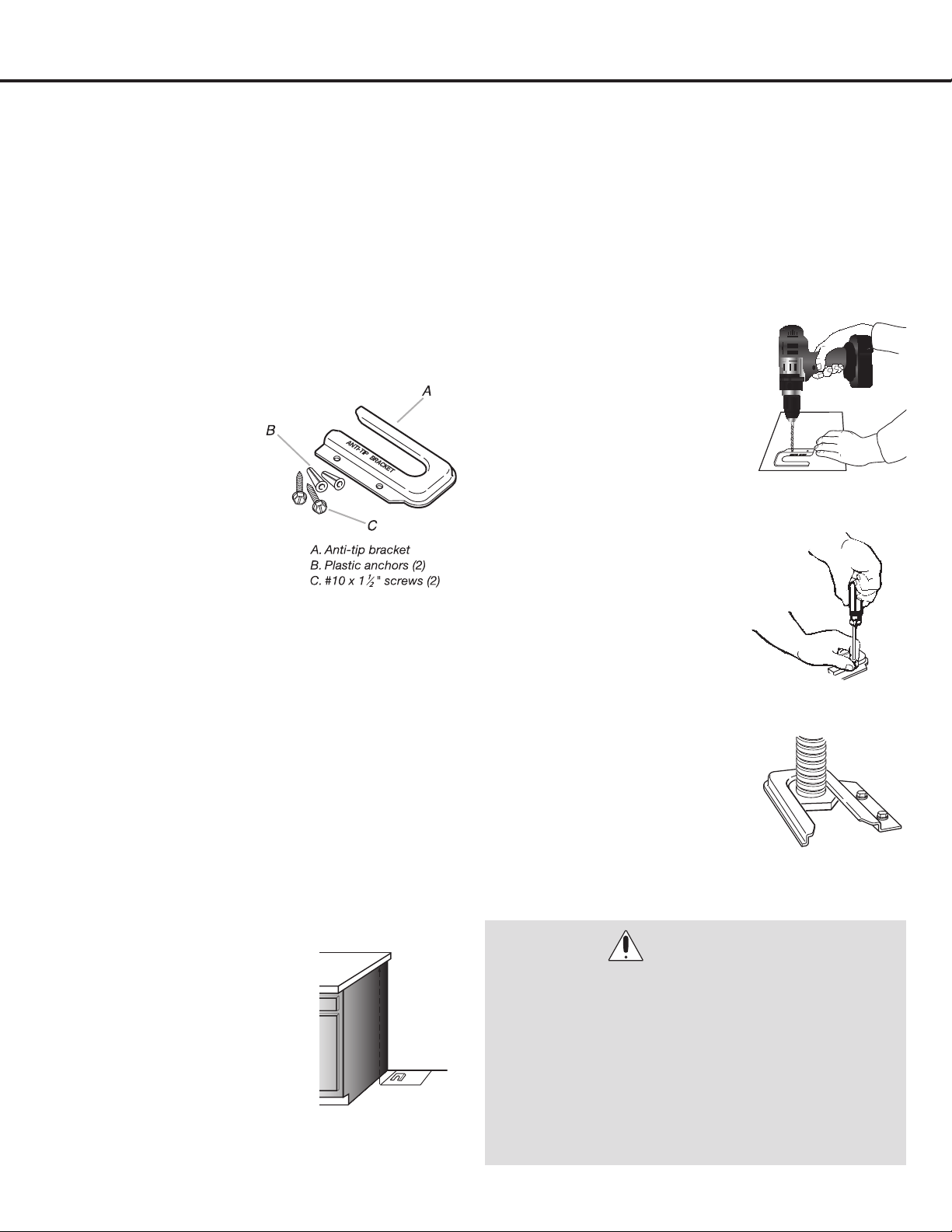
u
Contact a qualied
oorcoveringinstaller
for the procedure
of drilling mounting
holes through your
typeofoorcovering.
Retrieve the Anti-Tip
Bracket, two plastic
anchors and two
screws.
v
You will need additional tools not mentioned in the
“ToolsNeeded”sectiondependingonthetypeof
ooringasfollows:
Concrete/Ceramic Floors:3/16”(4.8mm)Masonry
Drill Bit
Wood Floors:1/8"(3.2mm)DrillBit
Masking Tape
Hammer
w
The Anti-Tip Bracket is to be installed on the left
rear leg. Follow these steps to secure the range to
theoorbeforemovingtherangeintonalopera-
ting position.
x
Place the template on
oorincabinetopening
(where the range will be
located) so that the left
edge is against cabinet
and top edge is against
rear wall, molding
or cabinet. (See Figure 21)
y
Tape template in place.
U
If countertop is deeper than 25” (63.5 cm),
measure and mark a distance of 25” (63.5 cm) in
from the front of countertop and align template
with mark.
V
TomountAnti-TipBrackettowoodoor,drilltwo
1/8”(3.2mm)pilotholesatthepositionsmarked
on the bracket template. Remove template from the
oor.
To mount Anti-Tip Bracket
to concrete or ceramic
oor,usea3/16”(4.8mm)
masonry drill bit to drill two
pilot holes at the positions
marked on the bracket
template. Remove template
fromtheoor.Tapplastic
anchors into holes with a
hammer.
W
Align Anti-Tip Bracket holes
withholesinoor.Fasten
Anti-Tip Bracket with
screws. (See Figure 23)
X
Move range close to
opening. Remove shipping
base, cardboard or
hardboard from under range,
if used. Move range into nal
position making sure rear
leveling leg slides into Anti-
Tip Bracket. (See Figure 24)
WARNINGS:
•PleasemakesuretoreadALLsafetyprecautionson
pages 4 to 10.
•Usetwoormorepeopletomoveandinstallrange.
•Tip-overHazard.
•Achildoradultcantiptherangeandbekilled.
•Connectanti-tipbrackettorearrangefoot.
•Reconnecttheanti-tipbracket,iftherangeismoved.
•Failuretofollowtheseinstructionscanresultindeath
or serious burns to children and adults.
Installation
Figure 21
Figure 22
Figure 23
Figure 24
— 22 —
Installation
STEP 7
Burner Rings and Caps Placement
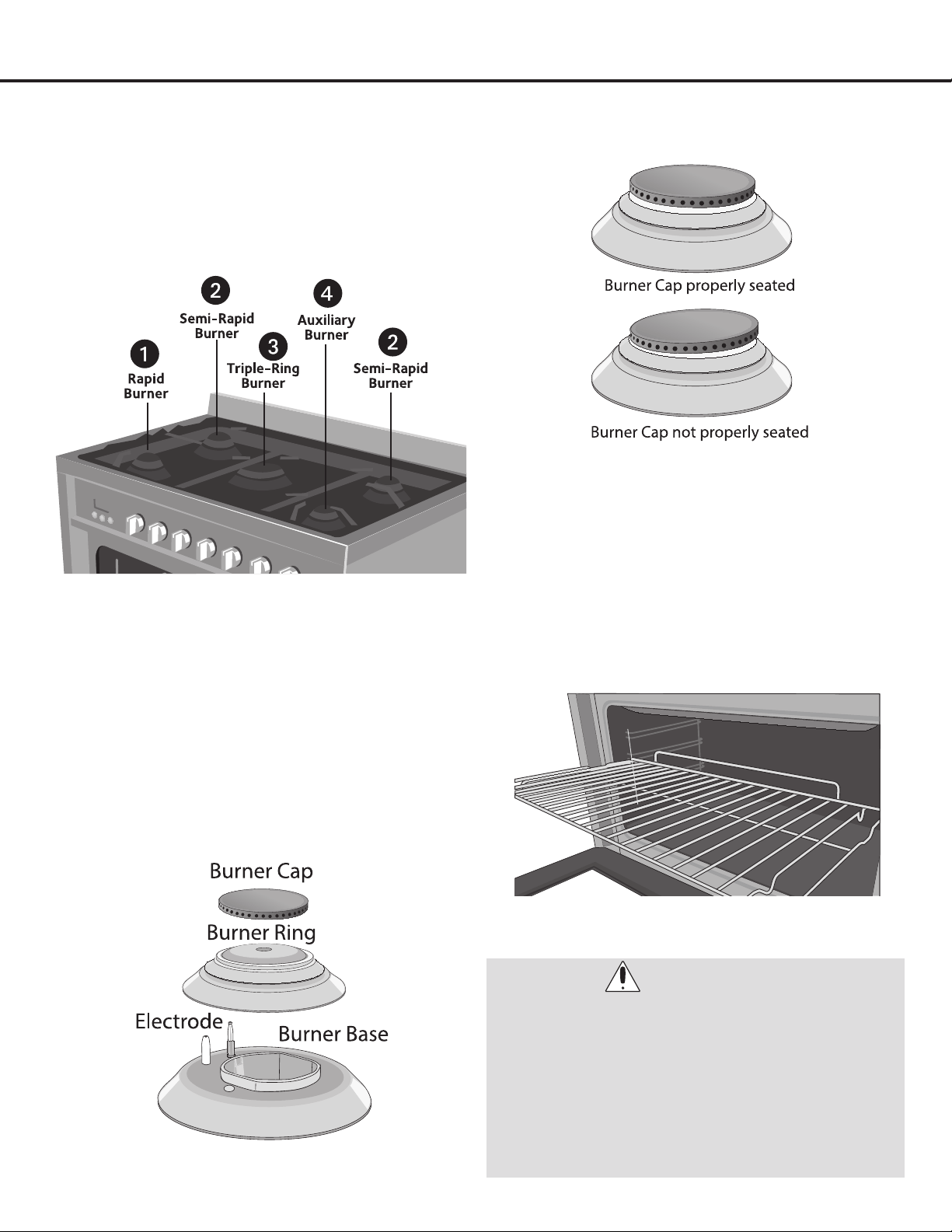
u
See below for Location of the Burners, as well as
the illustrations of the burner caps and heads. (See
Figure 25
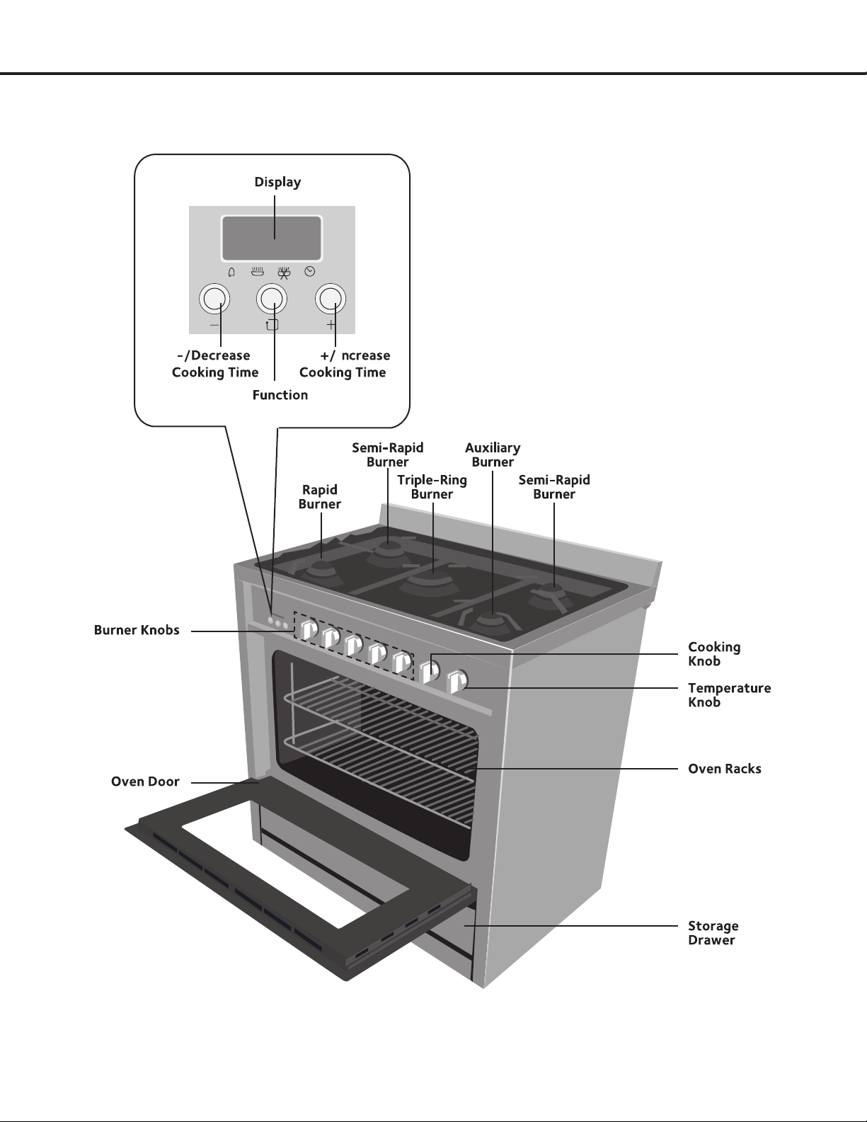
1. Rapid burner ( Front left) – 8,500 BTU
2. Semi-rapid burners (Rear left and right) – 7,000 BTU
3. Triple-ring burner – (Center) 18,000 BTU
4. Auxiliary burner (Front right) - 5,000 BTU
v
Place each burner cap on the matching burner ring.
The cap for each burner has an inner locating ring
which centers the cap correctly on the burner ring.
Be sure that all the burner caps and burner rings are
correctly placed BEFORE using your appliance. (See
Figure 26)
w
Make sure each burner cap is properly aligned and
level, then place the two grates and one triple ring
grate over the burners. (See Figure 27)
x
Test operation
of the electric igniters after the range
and supply line have been carefully checked for
leaks and the range has been connected to the
electrical power (see page 23). Push and turn a
burner until clicking is heard. All ve ignition pins will
spark, but only the open valve will ignite.
y
Insert the oven racks. (See Figure 28)
Figure 28
WARNINGS:
• PleasereadALLsafetyprecautionsonpages4to
10.
• Donotservicethesealedburneryourself.Contact
a qualified service professional.
• Theelectrodeoftheelectronicignitionsystem
is positioned above the surface of the burner
base. Do not remove a burner cap or touch the
electrode of a burner while another is turned on.
Damage or electrical shock may occur.
Figure 25
Figure 26
Figure 27
— 23 —
Installation
STEP 8
Connect to AC
WARNING:
• Neverusereductions,shunts,oradapterswhich
can cause overheating or burning.
• MakesuretheACSupplycabledoesnotcomein
contact with any parts or components that get hot.
DANGER:
• PleasemakesuretoreadALLsafetyprecautionsonpages4to10.
• ElectricalShockHazard.
• Donotuseanadapter.
• Donotuseanextensioncord.
• Failuretofollowtheseinstructionscanresultindeath,fire,orelectricalshock.
• Electricalconnectionmustbeperformedbyaqualifiedservicetechnicianinaccordancewiththekitinstructions
and all local codes and requirements.
• Thesafetycircuit-breakerandtheelectricalsystemmustbeabletowithstandtheloadoftheappliance.Seerating
label on back of range.
• Ratingplateislocatedonbackofrangeshouldyouneedtoverifyanyoftheelectricalrequirements.
• Thepowersupplysystemshouldhaveagroundconnectioningoodworkingorderinaccordancewiththe
regulations in force.
•
The electrical socket must be easily accessible with the appliance installed. In all cases, the power supply lead must
be positioned so that it does not reach a temperature of 50°C (122°F) above the room temperature at any point.
• Themanufacturerisnotliableforanydirectorindirectdamagecausedbyfaultyinstallationorconnection.Itis
therefore necessary that all installation and connection operations are carried out by qualified personnel, complying
with the local and general regulations in force.
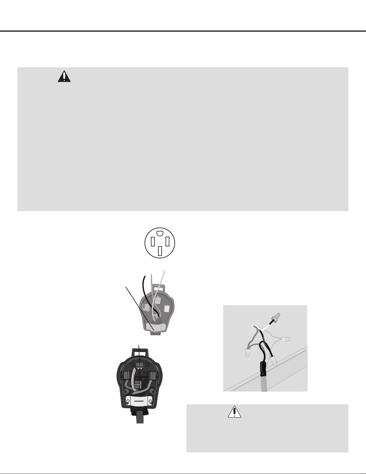
Connecting to the AC Plug Connecting Directly to the Wall
u
A 4-pronged 250 volt, 40 amp outlet
must be installed to match the plug
for this unit. (See Figure 29)
v
Unscrew the back panel of the plug,
then unscrew the wire holder
bracket. (See Figure 30)
w
The appliance is equipped with;
one black wire, one red wire,
oneyellow/green(ground)wire.
Secure the appliance wires to
the plug tightly. (See Figure 31)
x
Trim the appliance
wires to t inside
the plug. Connect
the wires to their
respective terminals on
the plug, leaving the
middle slot open. Note
that the ground wire
goes in the top slot
and the two live wires
go in the right and left
slots. (See Figure 31)
y
Replace back cover of the plug, securing it with the
screw(s).
u
Connect the wires to the wall as follows (See Figure
32):
Red Wire to Red Wire.
Ground Wire to Ground (Green) Wire.
Black Wire to Black Wire.
Do not connect White Wire; leave cap on end.
Figure 30
Figure 29
Figure 32
Figure 31
Bracket
Ground

— 24 —
Safety Before Operating
Safety Precautions
BeforeoperatingthisapplianceitisVERYimportantthat
you read the safety precautions on pages 4 to 10 as well as
all safety precautions listed on this and the following pages
with the header, “Safety Before Operating”.
•Makesureyourrangeisproperlyadjustedbyaqualied
service technician or installer for the type of gas (natural
or LP) that is to be used. Your range can be converted
for use with either type of gas. See the installation
instructions section in this manual. These adjustments
must be done by a qualied service technician according
tothemanufacturer’sinstructionsandallcodesand
requirements of the authority having jurisdiction. Failure
to follow these instructions could result in serious injury
or property damage. The qualied agency performing this
work assumes responsibility for the conversion.
•Longtermuseofyourrangecanresultinhighoor
temperatureswhichcouldharmmanytypesofoor
coverings. Never install the range over vinyl tile or
linoleum that is not specically designed to withstand
high temperatures. Never install it directly over interior
kitchen carpeting.
•Itemsofinteresttochildrenshouldnotbeplacedin
cabinets above a range or on the backsplash of a
range—children climbing on the range to reach items
could be seriously injured.
•
DO NOT leave children alone or unattended where a range
is hot or in operation. They could be seriously burned.
•
DO NOT let anyone climb, stand or hang on the oven door,
warming drawer or cooktop. They could damage the range
or cause it to tip over which could result in severe personal
injury.
•NEVERuseyourrangeasaspaceheatertoheator
warm the room. Doing so may result in carbon monoxide
poisoning and overheating of the oven.
•NEVERwearloosettingorhanginggarmentswhile
using the appliance. Be careful when reaching for items
placed in cabinets over the range. Flammable material
couldbeignitedifbroughtincontactwithameorhot
oven surfaces and may cause severe burns.
•DO NOTplaceammablematerialsinanoven,
a warming drawer or near a cooktop.
•DO NOT place or use combustible materials such as
gasolineorotherammablevaporsandliquidsinthe
vicinity of this or any other appliance.
•DO NOTallowcookinggreaseorotherammable
materials in or near the range.
•DO NOTusewaterongreaseres.Nevertouchaaming
pan.Turnthecontrolsoff.Smotheraamingpanon
a surface burner by covering the pan completely with
awell-ttinglid,cookiesheetorattray.Agreaserecan
be put out by covering it with baking soda or, if available,
by using a multi-purpose dry chemical or foam-type
re extinguisher. Flame in the upper oven or lower oven
drawer can be smothered completely by closing the oven
door or drawer and turning the control to off, or by using
a multi-purpose dry chemical or foam-type re
extinguisher.
•DO NOT use the oven or the drawer for storage.
•Allowtheburnergratesandothersurfacestocoolbefore
touching them.
•NEVERblockthevents(airholes)oftherange.They
provide the air inlet and outlet that are necessary for
the range to operate properly with correct combustion.
Air openings are located at the rear of the cooktop,
at the top and bottom of the oven door, and at the
bottom of the range under the warming drawer.
•Stepping,leaningorsittingonthedoorsordrawers
of this range can result in serious injuries and also cause
damage to the range. DO NOT allow children to climb
or play around the range. The weight of a child on an
open door may cause the range to tip, resulting in serious
burns or other injury.
•Leaktestingoftheapplianceshallbeconducted
accordingtothemanufacturer’sinstructions.
•Makesureyourrangeisproperlyinstalledandgrounded
by a qualied installer, according to the installation
instructions. Any adjustment and service should be
performed only by qualied gas range installers or
service technicians.
•Topreventpooraircirculation,placetherangeout
of kitchen trafc path and out of drafty locations.
•DO NOT attempt to repair or replace any part of your
range unless it is specically mentioned in this manual.
All other service should be referred to a qualied
technician.
•Makesureallpackagingmaterialsareremovedfrom
the range before operating it to prevent re or smoke
damage should the packaging material ignite.
— 25 —
Safety Before Operating
Surface Burner Safety
•NEVERleavethesurfaceburnersunattendedathigh
amesettings.Boiloverscausesmokingandgreasy
spillovers that may catch on re.
•AlwaysturntheburnerknobtotheIgnite (
) position
when igniting the top burners and make sure the burners
have ignited.
•Controlthetopburneramesizesoitdoesnotextend
beyondtheedgeofthecookware.Excessiveameis
hazardous.
•Useonlydrypotholders—moistordamppotholders
on hot surfaces may result in burns from steam. DO
NOTletpotholderscomenearopenameswhenlifting
cookware. DO NOT use a towel or other bulky cloth
instead of a pot holder.
•Whenusingglasscookware—makesureitisdesigned
for top-of-range cooking.
•Topreventburns,ignitionofammablematerialsand
spillage, cookware handles should be turned toward the
side or back of the range and should not extend over
adjacent burners.
•
NEVERplaceanyitemsonthecooktop.Thehotair
fromtheventmayigniteammableitemsandwill
increase pressure in closed containers, which may
cause them to burst.
•Carefullywatchfoodsbeingfriedatahighamesetting.
•Alwaysheatfatslowly,andwatchasitheats.
•Iffryingcombinationsofoilsandfats,stirtogether
before heating.
•Useadeepfatthermometerifpossibletoprevent
overheating fat beyond the smoking point.
•Usetheleastpossibleamountoffatforeffectiveshallow
or deep-fat frying. Filling the pan too full of fat can cause
spillovers when food is added.
•DO NOTcookfoodsdirectlyontheame(withoutapot
or pan), use proper cookware.
•DO NOT use a wok on the surface burners if the wok has
a round metal ring that is placed over the burner grate
to support the wok. This ring acts as a heat trap, which
may damage the burner grate and burner ring. Also, it
may cause the burner to work improperly and may cause
a carbon monoxide level above that allowed by current
standards, resulting in a health hazard.
•Foodsforfryingshouldbeasdryaspossible.Frostor
moisture on foods can cause hot fat to bubble up and
spill over the sides of the pan.
•NEVERtrytomoveapanofhotfat,especiallyadeepfat
fryer. Wait until the fat is cool.
•DO NOT place plastic items on the cooktop—they may
melt if left too close to the vent.
•Keepallplasticsawayfromthesurfaceburners.
•Topreventburns,alwaysbesurethattheBurnerknobs
are in the OFF position and all grates are cool before
attempting to remove them.
•Ifyousmellgas,turnoffthegastotherangeandcall
aqualiedservicetechnician.Neveruseanopename
to locate a leak.
•AlwaysturnBurnerknobtotheOFFpositionbefore
removing cookware.
•DO NOT lift the cooktop. Lifting the cooktop can cause
damage and improper operation of the range.
•Ifrangeislocatednearawindow,DO NOT hang long
curtains that could blow over the surface burners and
catch on re.
•DO NOT operate the burner for an extended period of
time without cookware on the grate. The nish on the
grate may chip without cookware to absorb the heat.
•Alwaysuseutensils/cookwarefortheirintendedpurpose.
Followmanufacturer’sinstructions.Someutensils/
cookware were not made to be used in the oven or on the
cooking surface.
WARNINGS:
•Ifthetopburneramegoesout,gaswillcontinue
toowtotheburneruntiltheknobisturnedtothe
OFF position.
•DonotleavetheburnersONunattended.
•Useproperpot/pansize—DONOTusepansthat
are unstable or easily tipped. Select cookware
havingatbottomsandlargeenoughtocover
burner grates. To avoid spillovers, make sure
cookware is large enough to contain the food
properly. This will save both cleaning time and
prevent hazardous accumulations of food which
could ignite if left on the range. Use pans with
handles that can be easily grasped and remain
cool.
— 26 —
Safety Before Operating
Cook Meat and Poultry Thoroughly
•Cookmeatandpoultrythoroughly—meattoatleastan
INTERNAL temperature of 160°F and poultry to at least
an INTERNAL temperature of 180°F.
•Toprotectagainstfood-borneillness,alwayscooktothe
proper temperatures.
Oven
•DO NOT heat closed food containers. Pressure could
increase and the container could burst, causing an injury.
•DO NOT use aluminum foil anywhere in the oven except
as described in this manual. Doing so could create a re
hazard or cause damage to the range.
•DO NOT use the oven for a storage area. Items stored
in the oven can catch on re.
•Keeptheovenfreefromgreasebuildup.
•Onlyinsert/replacetheovenrackswhentheoveniscool.
•Whenremovingfood,slideracksoutuntilthestop
engages, then remove food items to prevent burns
caused by touching the hot surfaces of the door or oven
walls.
•Whenusingcookingorroastingbagsintheoven,follow
themanufacturer’sdirections.
•Useonlyglasscookwarethatisrecommendedforuse
in gas ovens.
•Alwaysremovethebroilerpanfromtherangeafteryou
nish broiling. Grease left in the pan can catch re if oven
is used without removing the grease from the broiler pan.
•
When broiling meat, trim excess fat as it may ignite when it
istooclosetotheame.
•Makesurethebroilerpanisinplacecorrectlytominimize
the possibility of grease res.
•Ifyoushouldhaveagreasereinthebroilerpan,turn
the Cooking and Temperature knobs to the OFF positions
and keep the oven door closed to contain re until it
burns out.
•Forsafetyandbettercookingperformance,alwaysbake
andbroilwiththeovendoorclosed.WARNING:NEVER
block any slots, holes or passages in the oven bottom
or cover an entire rack with materials such as aluminum
foil.Doingsoblocksairowthroughtheovenandmay
cause carbon monoxide poisoning. Aluminum foil linings
may also trap heat, causing a re hazard. NOTE: Open
door baking or broiling can cause damage to the knobs
or valves. DO NOTLEAVETHEOVENDOOROPEN
DURING COOKING OR COOL DOWN.
READ AND FOLLOW THIS
SAFETY INFORMATION
CAREFULLY.
SAVE THESE
INSTRUCTIONS!
WARNINGS:
•NEVER block any slots, holes or passages in the
oven bottom or cover an entire rack with materials
suchasaluminumfoil.Doingsoblocksairow
through the oven and may cause carbon monoxide
poisoning. Aluminum foil linings may also trap heat,
causing a re hazard.
•Whenopeningthedoorofahotoven,standaway
from the range. The hot air and steam that escape
can cause burns to hands, face and eyes.
— 27 —
Operation
Location of Controls
I
— 28 —
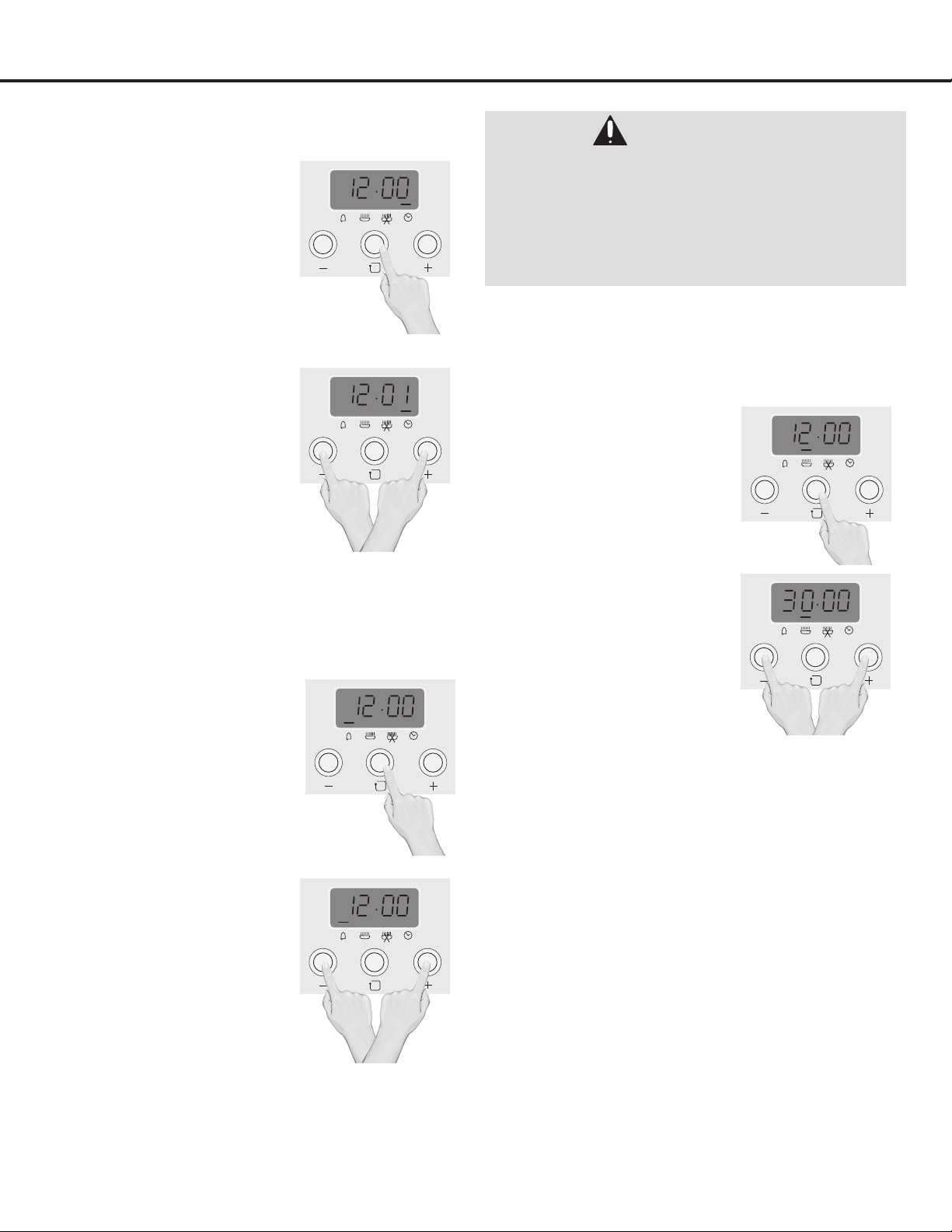
Setting the Clock
u
When rst connected
to AC power or after a
power outage, the display
willblink“12:00”andthe
Clock indicator will blink.
You can enter the Time
Setting mode manually by
pressing and releasing the
Function button until the
Clock indicator blinks.
v
To set the correct time,
press the + or – button
to advance forward
or backward until the
correct time is displayed.
When nished, press the
Function button, or wait
ve seconds; the time will
then be set.
IMPORTANT: Clock must be set
in order for the oven functions to
work.
Setting the Timer
u
Enter the Time Setting
mode by pressing the
Function button once; the
Timer indicator will light.
v
Set the desired timer time
using the + or – button
to advance forward or
backward until the desired
time is displayed. The
timer will count down and
beep when it is nished.
Oven Timed Cooking
Start Time
To start cooking time, set the TIMER to desired start time
BEFORE setting oven function and temperature.
u
Press and release the
Function button until the
Start indicator blinks.
v
Set the start time by
pressing the + or – button
until the desired start time
is displayed.
w
Set the Temperature and
Cooking knobs as desired
(see pages 30 to 32 for
descriptions and operation) and place the food in
the oven.
Note: Oven will not operate until the programmed Start time
is reached. To operate oven before the Start time, the Timer
function must be cancelled.
End Time
To end cooking time, set theTIMER to desired shut off time:
u
Press the Function button again until the the End
indicator blinks.
v
Set the end time by pressing the + or – button
until the desired end time is displayed. Press the
Function button again to set.
w
When the end of desired cooking time is reach, the
unit will beep. Rotate the Temperature and Cooking
knobs to their OFF positions, and then press the
Function button to turn off the beeping.
Operation
WARNING:
•Use caution with the timed cooking. Use only
when cooking cured or frozen meats or most fruits
and vegetables. Timer function should be used
with caution when cooking foods that can easily
spoil, such as milk, eggs, sh, meat or poultry.
Eating spoiled food can result in sickness from
food poisoning.
— 29 —
Operation
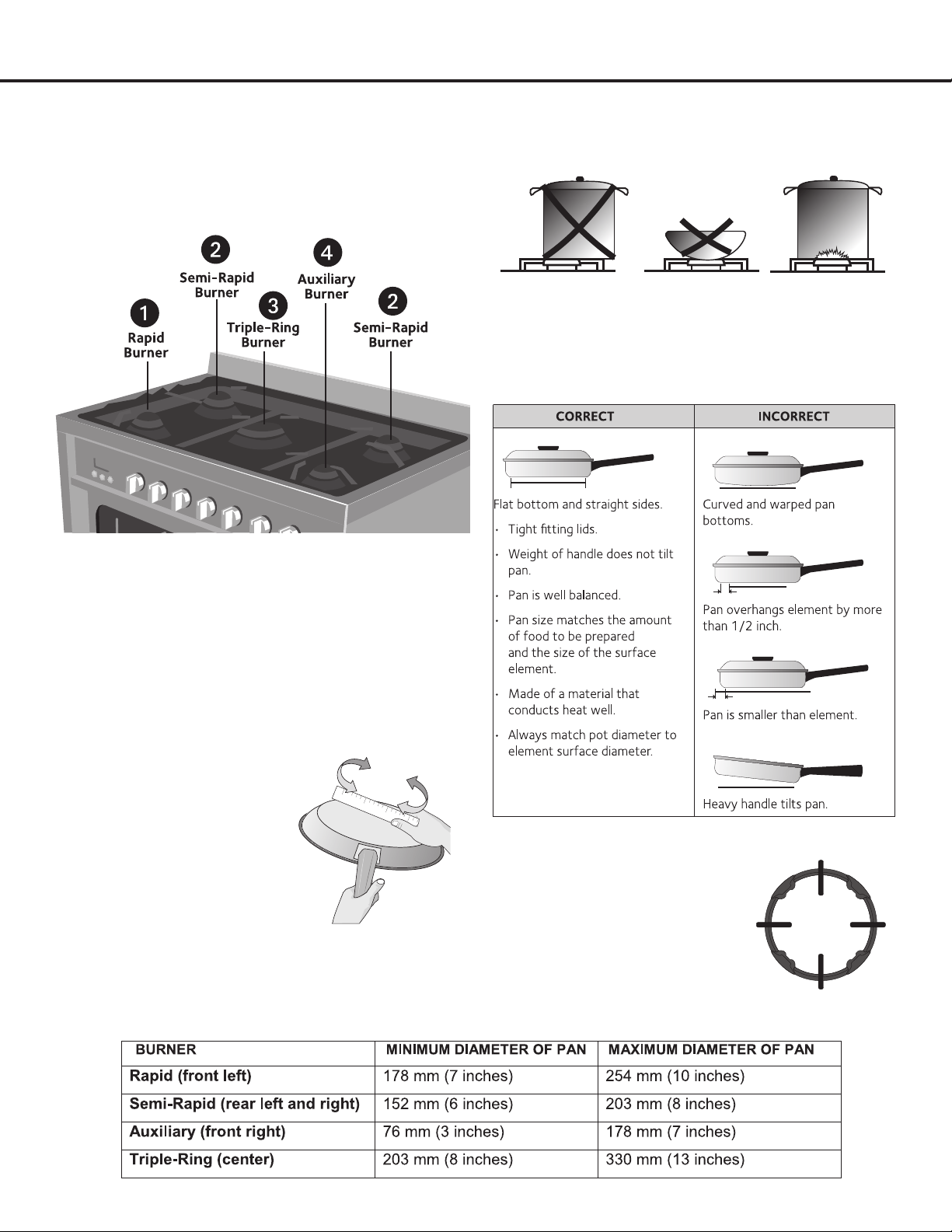
u
Each burner has a different BTU; chose the
appropriate burner(s) for best result.
1. Rapid burner and 2. Semi-rapid burners: Primary
burners for most cooking - Rapid burner has a slightly
higher BTU.
3. Triple-ring burner: Maximum output burner designed to
quickly bring large amounts of liquid to a boil or for higher
heat level cooking requirements.
4. Auxiliary burner: The lowest BTU burner for precise
cooking performance for foods that require low heat at
longer cooking times.
v
For lower gas
consumption and better
efciency:Useonlyat-
bottomed cookware.
Checkforatnessby
rotating a ruler across the
bottom of the cookware;
there should be no gaps
between the pan and ruler.
Use cookware with dimensions
suitable for each burner. (See Table
Figure 33)
Assoonasaliquidcomestoaboil,turntheamedowntoa
level that will keep it at a simmer.
w
To avoid potential hazards and prevent uneven
cooking it is important to place cookware directly on
the burner (See above illustration).
Using the appropriate cookware will also help
reduce cooking times and cook food more evenly
(See Chart Figure 34)
TRIPLE PAN SUPPORT:
The Triple Pan Support (included)
is used to stabilize larger pots or to
support food simmer. It can be used
with all burners although it is most
commonly used for the triple burner.
Burners and Cookware
N
Figure 33
Figure 34
— 30 —
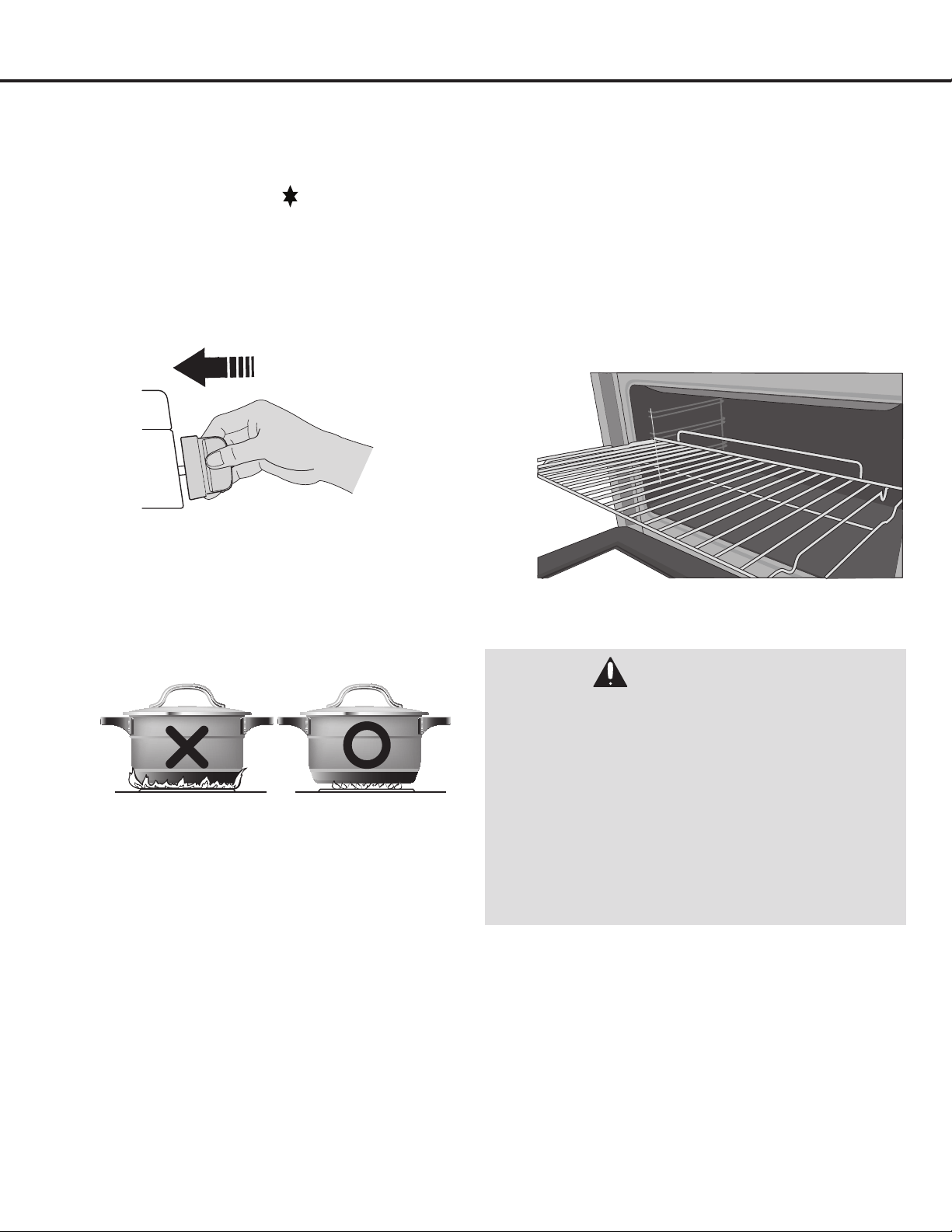
u
Igniting the burner: Push in and rotate the desired
Burner knob to the Ignite ( ) position (clicking
sound will be heard). Continue pressing the Burner
knob (5 to 10 seconds). This is necessary to heat
up the thermocouple and activate the safety valve,
whichwouldotherwisecutoffthegasow.
If the burner fails to ignite, wait one minute for the
gas to dissipate before attempting to reignite.
v
Adjusting the ame: Rotate the Burner knob
counter-clockwise to the desired position (See Page
36).
Flames should not extend up the sides of the
cookware. Flames extending beyond the bottom of
the cookware will not speed up cooking time and
could be hazardous.
w
Turning the ame off: Push in and rotate the
desired Burner to the OFF position. Always turn
theameoffbeforeremovingcookwarefromthe
burners.
In case of a power failure, place a lit match near the burner
and follow Step 1. If the burner does not light after a few
attempts, check that the burner cap and burner ring are
correctly positioned. (See Page 22)
Placing the Oven Racks: The oven has four rack positions
for various types of cooking.
To install an oven rack, insert the rack into the guides on
the oven wall. Tilt the front of the rack upward and slide into
place.
To remove an oven rack, pull the rack forward until it stops.
Tilt the front of the track upward and pull out.
Oven Racks
WARNINGS:
ALWAYS ARRANGE OVEN RACKS WHEN THE OVEN
IS COOL
•Always use potholders or oven mitts when removing
food or adjusting the oven racks.
•Oven racks may be HOT and may cause burns.
•NEVER cover the oven walls or bottom with
aluminum foil. Aluminum foil will melt to the interior
surface of the oven and cause permanent damage
to the oven.
•DO NOT cover racks with aluminum foil as this will
affect heat distribution and produce poor baking
results.
Operation
Burner Cooking
— 31 —
OFF
Operation
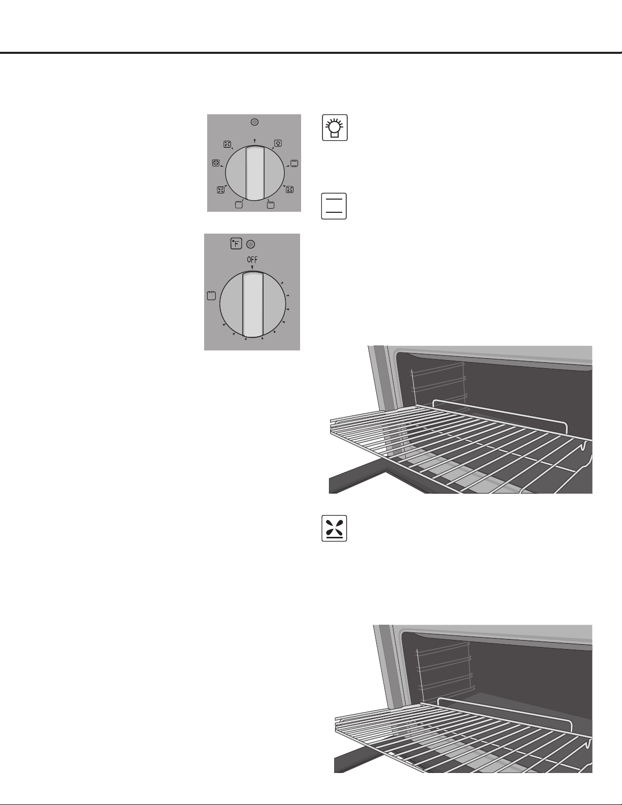
u
Rotate the Cooking knob to
select the desired Cooking
Mode.
The Cooking Indicator will
light when activated and turn
off when desired tempertature
is reached.
v
After selecting the desired
Cooking Mode (See
following section), rotate the
Temperature knob to the
desired temperature.
The Temperature indicator
light will turn on while
preheating and will turn off
when fully preheated.
The Temperature indicator
mayickeronandoffwhile
the oven maintains the desired temperature.
w
Preheating: Wait until the oven reaches its set
temperature before placing the food in the oven.
Preheating is necessary for satisfactory results
when baking cakes, cookies, pastries and breads.
For best baking results, pans should be centered
on the racks. If baking with more than one pan,
place the pans so that each one has at least 1” to
1-1/2”ofairspacearoundthem.
x
When cooking is completed, rotate both knobs to
their OFF positions.
LIGHT
Rotate the Cooking Knob to this position to turn on
theovenlight.Heatwillnotbeproducedbythe
oven while the oven light is turned on.
TRADITIONAL COOKING
(Upper and lower elements and Fan) 140° F TO
MAX:
Heatisproducedfromthetopandbottom
elements. The oven must be preheated before the
food is placed inside the oven.
Traditional Cooking mode provides optimum results
with cakes, pizzas, bread and for foods such as
casseroles.
For best results, when using this mode, place the
food on the second or third rack (as shown below).
DELICATE COOKING
(Lower element and Fan) 140° F TO MAX:
Heatisproducedfromthebottomelementandthe
convection fan.
The Delicate Cooking mode is ideal for moist
pastries, cakes and dessert molds.
For best results, when using this mode, place the
food on the bottom rack (as shown below).
Oven Controls
Oven Cooking Modes
MAX
140
180
210
250
280
320360
390
430
— 32 —
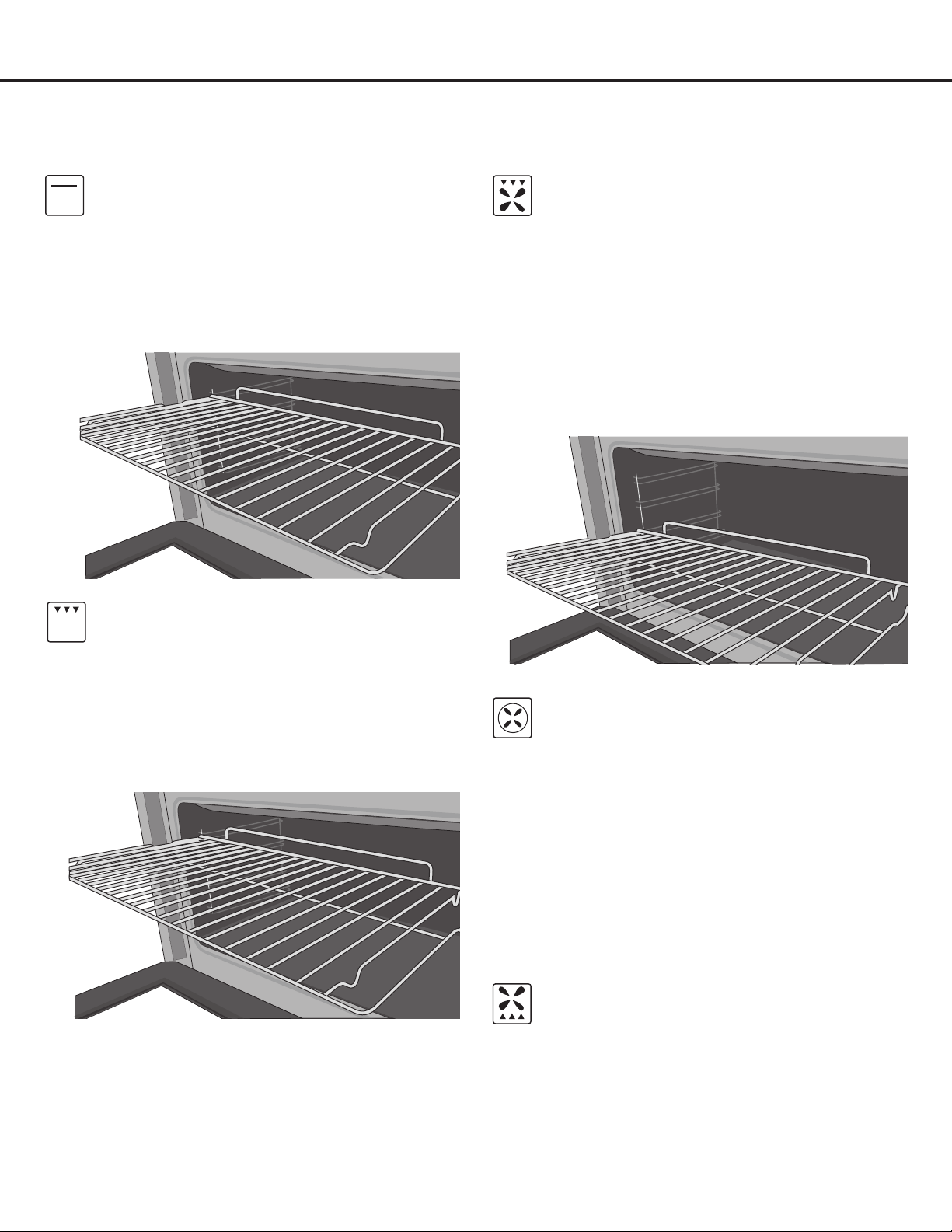
BROWNING
(Upper element and fan) 140° F TO MAX:
Heatisproducedfromtheupperelementandthe
convection fan.
The Browning mode best used to gently brown
dishes at the end of the cooking time period.
For best results, when using this mode, place the
food on the top or second rack (as shown below.)
BROIL COOKING
(Grill element) 140° F TO MAX:
Heatisproducedfromthegrillelement.
The Broil Cooking mode is best reserved for melting
cheese, toasting and browning. The Broil Cooking
time should not be any longer than 5 minutes.
For best results, when using this mode place. item
on the top or second rack (as shown below.)
FAN ASSISTED GRILL COOKING
(Grill element and Fan) 140° F TO 392° F:
Heatisproducedfromthegrillelementandthe
convection fan.
The Fan Assisted Grill Cooking mode is best used
for grilling meats, vegetables and poultry.
For best results, preheat the oven and place the
food on the second or third rack of the oven (as
shown below).
Other racks may be used simultaneously using this
mode.
CONVECTION COOKING
(Cooking element and Fan) 140° F TO MAX:
Convection Cooking mode permits even-heat multi-
rack cooking for various types of foods with the
appropriate cooking times for each dish.
The oven must be preheated before the foods are
placed inside.
When baking cookies or biscuits, you should use
pans with very low sides to allow the heated air to
circulate around the food.
Using a pan with a dark nish will allow faster
cooking times.
DEFROST
(Bottom fan) 140° F TO MAX:
Defrost mode permits all types of frozen food to
be defrosted by circulating room temperature air
around the food.
For foods such as meat, sh and bread, set the
Temperature knob to 350-400° F.
Operation
Oven Cooking (Continued)
— 33 —
Operation
Cooking Chart

— 34 —
Care and Maintenance
Control Knobs
To clean, use a damp soapy cloth for everyday cleaning of
the knobs. For heavier cleaning for grease, etc., apply a non-
abrasive liquid detergent to a damp cloth. Clean and then
dry completely.
Make sure not to rotate the knobs when cleaning.
Burner Grates
These three grates should only be used in their proper
positions. DO NOT operate a burner for an extended period
of time without cookware on the grate. To clean, AFTER
COOLING, use hot water or white vinegar, and DO NOT
place in a dishwasher. When replacing the grates, be sure
they are positioned securely over the burners.
Please note that the grates have rubber pads on the feet
that come into contact with the range to avoid scratches.
After cleaning it is important to verify that these rubber pads
are still there. Should they come off, they can be reapplied
using a heat-resistant adhesive.
Burner Rings
Lift off when cool. Wash burner rings in hot, soapy water and
rinse with clean water. To remove burned-on food particles,
you may scour with a plastic scouring pad. Thoroughly dry
before returning the rings to the range.
The rings are NOT dishwasher safe.
Do not use cleaners for stainless steel surfaces as these
rings are not stainless steel.
Oven Door Exterior
To clean, apply the glass cleaner onto a sponge and clean.
Do not spray cleaner directly onto the door.
Burner Caps
Lift off when cool. Wash Burner Caps in hot, soapy water
and rinse with clean water. Remove any food from between
the burner slots using a small non-abrasive brush like a
toothbrush, and afterwards wipe using a damp cloth.
To remove deposits from the burner cavities, remove the cap
and separate the two parts. Clean the burner holes routinely
with a small gauge wire or needle and especially after bad
spillovers which could clog these holes.
Thoroughly dry before returning the heads to the range.
The heads are NOT dishwasher safe.
Stainless Steel
To clean the stainless steel surface, use warm sudsy water
or a stainless steel cleaner or polish. Always wipe the
surface in the direction of the grain. Follow the cleaner
instructions for cleaning the stainless steel surface.
DO NOT use a steel wool pad as it will scratch the surface.
Do not use cleaners with high concentrations of chlorides
or chlorines. Do not use harsh scrubbing cleaners.
Oven Cavity
This appliance does NOT have a self-cleaning feature.
Use an appropriate cleaning product designed specically to
clean the inside of ovens. IMPORTANT: Always follow label
instructions on cleaning products.
Lower Interior Lower Grill Element
To remove the element, support one side with your hand
while removing the retainer with the other.
To clean, use warm sudsy water or a cleaner specically
designed for this item. When cleaning, make sure not to apply
excessive force on the element as it is fragile. Reposition the
element and secure the retainer back in place.
DO NOT use the oven with the grill element hanging down—
it must be repositioned after cleaning.
Storage Drawer
Make sure the drawer is closed and then empty it
completely. Use a mild detergent to clean.
WARNINGS:
•PleasemakesuretoreadALLsafetyprecautions
on pages 4 to 10 and 25 to 27.
•Electric Shock Hazard.
•Toavoidpossibleburnsusecarewhencleaning
the appliance.
- DO NOT attempt to clean the appliance
whenever the oven or burner rings are still hot.
- DO NOT attempt any of the following cleaning
instructions before turning all burners and the
oven off, and allow them to completely cool.
IMPORTANT: Always follow label instructions on
cleaning products.
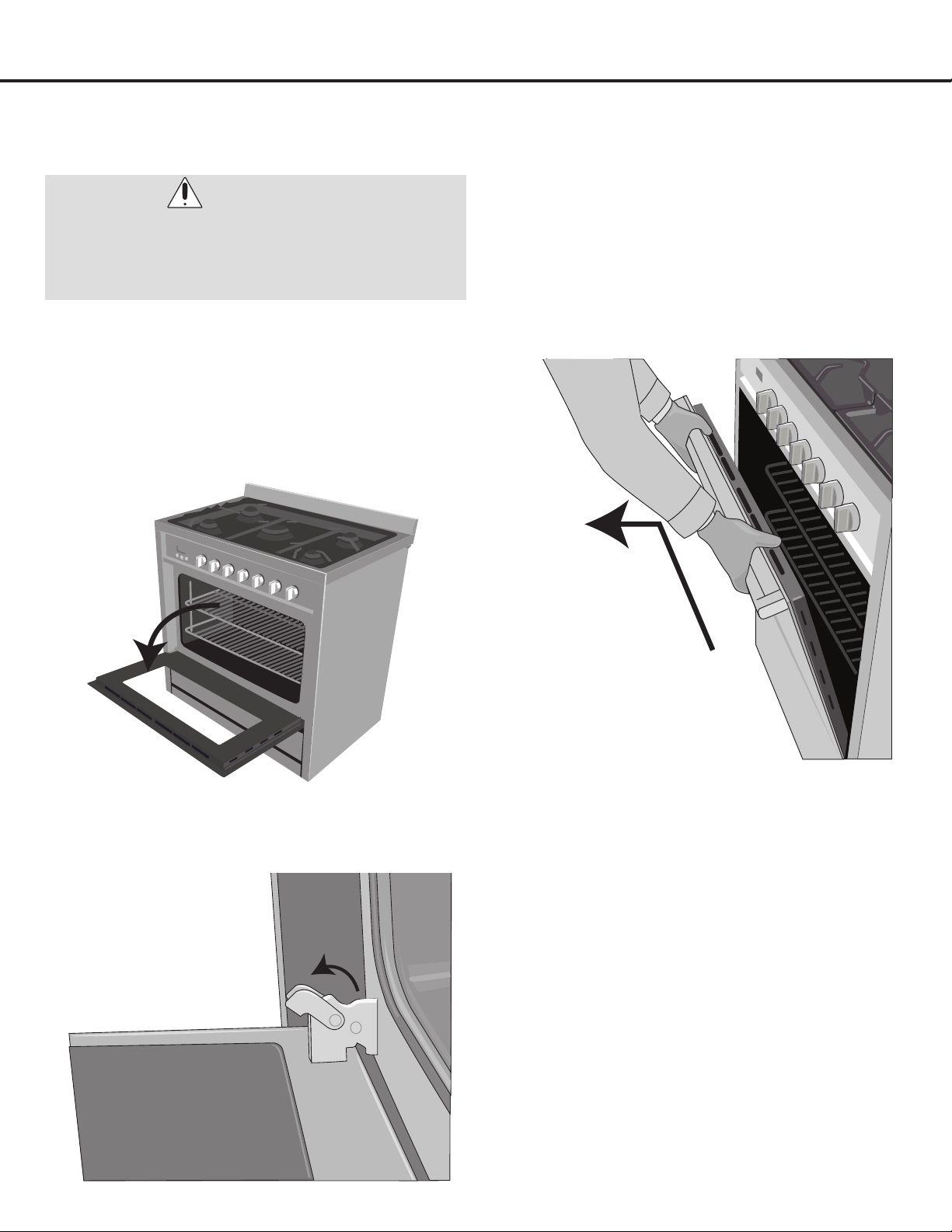
— 35 —
Care and Maintenance
For normal range use it is not suggested to remove the oven
door.However,ifremovalisnecessary,makesuretheoven
is off and cool. The oven door is heavy.
Follow these instructions.
u
Open the door fully.
v
Lift up and push the small levers located on the two
hinges all the way back to unlock.
w
While holding the door on each side, shut the door
until it touches the levers. Continue closing the door
untilitisabout4"(10cm)frombeingfullyclosed.
x
Pull the door towards you, pulling it out of its seat.
The door will gently come away from the oven. If
door does not come away from oven easily, do not
force it.
y
To replace the door, perform the previous steps in
reverse order.
Removing the Oven Door
WARNINGS:
•Theovendoorisremovable,butitisheavy.Youmay
need help removing and replacing the door.
•Becarefulwhenremovingandliftingthedoor.
•DONOTliftthedoorbythehandle.
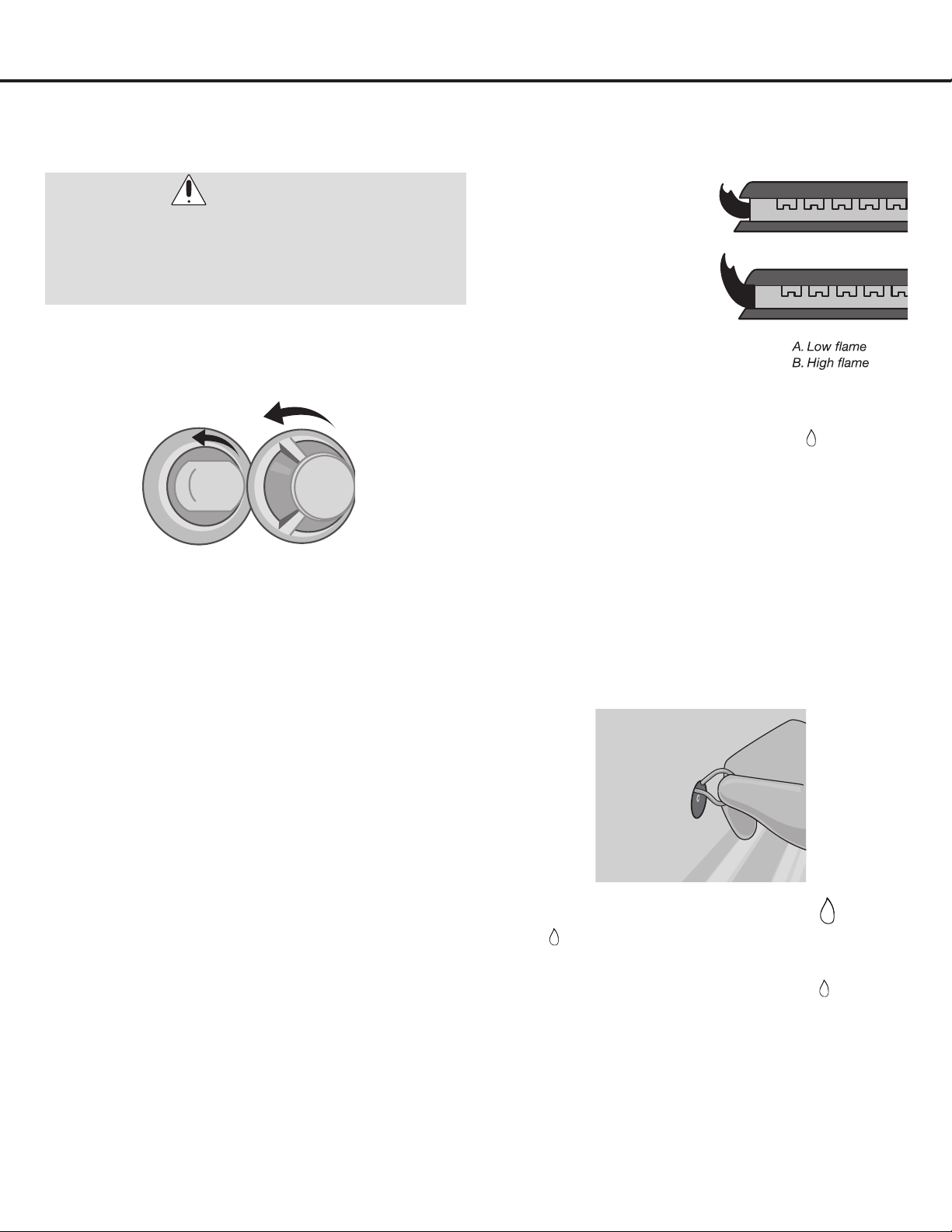
— 36 —
Care and Maintenance
u
Remove the glass cover by turning counter-
clockwise.
v
Remove the bulb by turning it counter-clockwise.
w
Replacethebulbwitha240V,25Wtypee-14bulb.
Reconnect power.
u
Turn all burners to their
highest settings and
checktheames.They
should be blue in color
and may have some
yellow tipping at the
endsoftheamewhen
using LP gas. Foreign
particles in the gas line
may cause an orange
ameatrst,butthis
will soon disappear.
v
Turn the desired burner knob to Low ( ) and
observetheame.
w
Set two other burners to Medium. This will prevent
theupperrowofamesfrombeingsettoolow,
resultingintheamebeingextinguishedwhenother
burners are turned on.
x
Toadjusttheame,removetheknobs;insertthe
included3/32screwdriverthroughtheaccesshole
to engage the brass slotted screw as shown. Make
the adjustment by slowly turning the screw until the
ameappearanceiscorrect.
Test 1:TurntheburnerknobfromHigh(
) to Low
(
)quickly.Iftheamegoesout,increasetheame
size and test again.
Test 2: With the burner knob on a
Low ( )
setting,
openandclosetheovendoorquickly.Iftheame
is extinguished by the air currents created by the
doormovement,increasetheameheightandtest
again.Iftheamesaretoosmalloruttered,open
thevalvemorethantheoriginalsetting.Iftheames
are too large, close the valve more than the original
setting.
Replacing the Light Bulb
Adjusting the Burner Flames
WARNINGS:
•Beforereplacingyourovenlightbulb,DISCONNECT
the electrical power to the range at the main fuse or
circuit breaker panel.
•Makesureovenandbulbarecooledcompletely.

— 37 —
Before Calling for Service
Before calling for service, review this list. It may save you both time and expense. This list includes common experiences
that are not the result of defective workmanship or materials in your appliance.
NOTHING WILL OPERATE
•Istheelectricalsupplydisconnected?
Verifythatelectricalwiresareconnectedtothemains
properly.See“ConnecttoAC”section.Iftheproblem
continues, contact a qualied technician.
•Isthehouseholdfuseblownorcircuit
breakertripped?
Replace the fuse or reset the circuit breaker. If the
problem continues, contact a qualied technician.
•Isthemainorregulatorgasshut-offvalveinthe
offposition?
See“GasConnection”sectionandrotatetothe
On position.
•Istherangeproperlyconnectedtothegassupply?
Contactaqualiedtechnician.See“Gas
Connection” section.
SURFACE BURNERS WILL NOT LIGHT
•
Isthisthersttimethesurfaceburnershavebeenused?
Turn on any one of the surface burner knobs to release
air from the gas lines.
•Didyoupushinontheknobbeforeturning?
The knobs require that they are pushed in before
rotation to prevent accidental turning.
•Aretheburnerportsclogged?
Cleantheburnerringsandcapsasstatedinthe“Care
and Maintenance” section.
SURFACE BURNERS ARE UNEVEN,
YELLOW AND/OR NOISY
•Aretheburnerportsclogged?
Cleantheburnerringsandcapsasstatedinthe“Care
and Maintenance” section.
•Aretheburnercapspositionedproperly?
See“BurnerRingsandCapsReplacement”section.
•Ispropanegasbeingused?
The range may have been converted improperly.
Contactaqualiedservicetechnician.See“Liqueed
Petroleum (Propane) Gas Conversion” section.
SURFACE BURNER MAKES
POPPING NOISES
•Istheburnerwet?
Burners cannot operate or light if wet, so let
completely dry.
OVEN MAKES POPPING NOISES
•Thisisnormal
This is the sound of the metal heating and cooling during
both the cooking and Off functions, and is normal.
EXCESS HEAT AROUND COOKWARE
ON COOKING SURFACE
•Isthecookwarethepropersize?
Use cookware about the same size as the surface
cooking area, element or surface burner. Cookware
shouldnotextendmorethan1/2”(1.3cm)outsidethe
cooking area.
COOKING RESULTS NOT WHAT
EXPECTED
•Isthepropercookwarebeingused?
Use the proper cookware as shown on page 29.
•
IstheTemperatureknobsettotheproperheatlevel?
Push in and rotate the Temperature knob to the desired
setting and let the oven preheat until it reaches the
temperature before you begin cooking.
•IstheCookingknobsettothepropersetting?
Push in and rotate the Cooking knob to the desired
setting; see pages 31 to 32 for description of icons.
•Istherangelevel?
Level the range as shown on page 15.
OVEN WILL NOT OPERATE
•Aretheovencontrolssetcorrectly?
See pages 30 to 32 to make sure the knobs are set
as intended.
•IstheOvenTimerset?
Oven will not operate when the Oven Timer is set; see
page 28.
COOLING FAN RUNS DURING BAKING
AND BROILING
•Itisnormalforthefantoautomaticallyrunwhilethe
oven is in use and for some time after during cooling.

— 38 —
Before Calling for Service
OVEN TEMPERATURE TOO HIGH OR
TOO LOW
•Wastheovenpreheated?
Push in and rotate the Temperature knob to the desired
setting and let the oven preheat until it reaches the
temperature before you begin cooking.
•Aretherackspositionedproperly?
See pages 31 to 32 for rack positioning.
•Isthereproperaircirculationaroundbakeware?
If bakeware takes up too much room, air circulation will
be reduced.
•Isthebatterevenlydistributedinthepan?
Check that batter is level in the pan when baking.
•Istheproperlengthoftimebeingused?
Make sure proper cooking time was used.
•Hastheovendoorbeenopenedwhilecooking?
Oven“peeking”releasesovenheatandcanresultin
longer cooking times.
•Arebakeditemstoobrownonthebottom?
Move rack to higher position in the oven.
•Arepiecrustedgesbrowningearly?
Usealuminumfoiltocovertheedgeofthecrustand/or
reduce baking temperature.
NO SPARK WHEN LIGHTING BURNER
•Electricalsupply-Theelectricalwiresortheplug
are not connected properly.
Connect with electrical power again. If the problem
continues, contact a qualied technician.
•Burner-Theburnerisnotinstalledcorrectly.
Installtheburneragain.See“BurnerRingsandCaps
Replacement” section.
•Sparkpin-Ignitionelectrodeandtheholearenot
inserted properly.
Installtheburneragain.See“BurnerRingsandCaps
Replacement” section.
THE FLAME GOES OUT ONCE
RELEASING THE KNOB
•Safetyvalve-Knobnotpresseddownlongenough.
Press and turn the knob again and hold down three
to ve seconds after the burner has been lit. This is a
safety feature.
BURNER WON’T IGNITE OR BURNS
UNEVENLY
•Gasvalve-Thevalveisnotopen.
Make sure the valve is completely open.
•Gaspipe-Theremaybeairinthegaspipe.
Igniterepeatedlyuntilamecatchestoreleasetheair
from the pipe.
•Burnercapissues.
The burner cap is not placed correctly; replace the
burner cap. Some holes in the lid are blocked; clean the
holes of the lid.
•Sparkpin-Thesparkpiniswetorcontaminatedby
the food.
Clean and dry the spark pin.
•Gasconnectingpipes-Thegasconnectingpipes
are blocked or pinched.
Contact a qualied technician. Adjust or change the
connecting pipes.
STRANGE SMELL
•Gasleak-Turnoffthegasandcontacta
qualied technician.
•Thegassupplypipeisoldand/orbroken.Change
the gas supply pipe.

— 39 —
Please register your product warranty by visiting the Ancona Home website.
Canada & USA
Phone: 888-686-0778
Fax: 800-350-8563
Email: [email protected]
Website: www.anconahome.com
Ancona is in association with Mr Appliance for all after sales service calls.
Please contact their service provider or visit their website:
Phone: 888-686-0778
Website: www.mrappliance.com
©2015CopyrightofAnconaHome.Allrightsreserved.Thismaterialmaynotbereproduced,displayed,modiedordistributed.
MAAN-2200-11
