
IMPORTANT SAFETY INSTRUCTIONS
Carefully read the following important information regarding
installation safety and maintenance.
Keep these instructions for future reference.
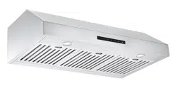
RANGE HOOD
USER INSTRUCTIONS
MODEL:
Under Cabinet 30 Inches
Square Buttons
450 CFM
08/23/2012


4
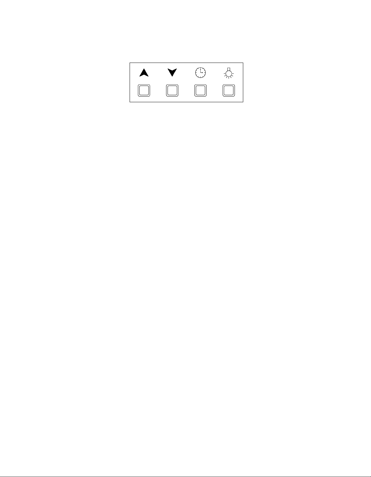
CONTROL PANEL OPERATION
Liquid Cristal Display controls
A- Lights and Power settings:
When the power is on the backlight is lit, the light will
t
urn off after 30 seconds of standby
Press the
button once and light will go on; press
again to shut off
The motor has 3 speed levels. Press the
button
once to start the motor at low speed, press again to
m
ove up to medium speed and once more to reach
maximum speed.
You can stop the motor by pressing the
button.
When re-opening the motor by pressing the
button again, the speed will be at the same setting as
wh
en last used.
B- Time Setting:
To set the time first turn off the lights and motor
Press the
button for 3 seconds and the first 2
numbers of the hour segment will flash
Press the
button to increase and the button to
decrease the time
Press the
button for 3 seconds again and the last
2 numbers of the hour segment will flash
Press the
button to increase and the button to
decrease the time
Press the button again to confirm time and exit
C- Timer Setting:
The control module provides the option to run the
motor for a predetermined time period in order to
evacuate remaining vapors from the kitchen.
The default time period is 5 minutes and can b
e
ad
justed from 1 to 60 minutes
In order to adjust the time period turn on the motor at
any speed
Press the
button to enter the timer setting mode.
Press th
e
button to increase the number of
minutes and press the
to decrease the number of
minutes the motor will run before stopping.
When you have reached the desired time length press
the
button again to confirm and initiate the timer
count down.
When pressing the
button next time, it will be set
to the newly adjusted time.
.
.
.,
.
.
.
.
.
.
,
.
Increase
Speed
Decrease
Speed
Timer Light
.
.
5
GENERAL INSTALLATION INSTRUCTIONS
A: GENERAL
Carefully unpack the hood but do not remove any
protective film until after installation to avoid
accidental damage or scratching. Place filters
somewhere safe for the same reason.
Check for damage, and lay out the hood pieces and
parts.
Range hoods do not come with wall or ceiling screws,
as the type of structure determines the type of screws.
Check that you have the right tools. In addition to
marking and measuring tools, a hammer, screwdrivers,
pliers and scissors, you may need sheet metal sheers,
and wire strippers. Safety glasses are recommended.
B: ELECTRICAL CONNECTION
This range hood must be grounded. If the dwelling
wiring is not 2-wire with a ground wire, a ground must
be provided by the installer.
Install a 5.08 X 10.16 cm (2” X 4”) wall outlet box and
3-blade 125 Volts, 15 amp grounded receptacle.
Use wire nuts to connect incoming ground, neutral and
hot.
Push wires into the junction box and replace cover. B
e
sure wires are not pinched.
C- INSTALLATION DISTANCE
Hood should be placed at a minimum distance from
the range top of:
– 61 cm (24”) for electric cooking surface
– 76 cm (30”) for Gas Cooking Surface
UNDERCABINET RANGE HOOD INSTALLATION
This range hood model is designed to be installed under kitchen cabinets.
If replacing a different model, check the location of the air exhaust in case it does not line up with the new mod
el;
T
he ducting location may have to be adjusted to the existing wall opening;
If the ventilation system is equipped with an external air duct with a different diameter, apply a reduction fitting.
A 6” Ø or rectangular 3” X 10” ducting is recommended for maximum performance and safety.
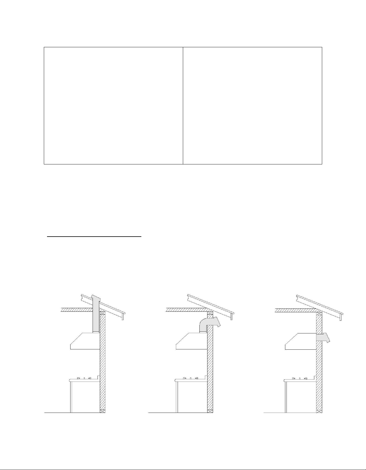
Section A: Select venting option
T
his unit offers 2 venting options:
A- Top venting (vertical) using 6” round or rectangular 3” X 10” damper
B- Rear venting (horizontal) using rectangular damper.
A1- Top venting Roof Exhaust A2- Top venting Wall Exhaust B- Rear Venting
;
;
6
A- Top venting using 6” round damper:
- If you require 6” round venting, keep the unit as provided in the packaging and install the round damper
provided;
- Position the damper on top of the unit and set in place with screws provided (see Pic 1 a, b, c)
- Connect duct work to damper
- Use Duct Tape to ensure joint is sealed and air tight
Pic 1
A- Top venting using rectangular damper
- If you require rectangular top (vertical) venting simply install the rectangular damper provided (see pic 2)
- Connect duct work to damper
- Use Duct Tape to ensure joint is sealed and air tight
Pic 2
;
;
.
;
:
;
.
(S
(S
7
Rear venting (horizontal) using rectangular damper
Ste
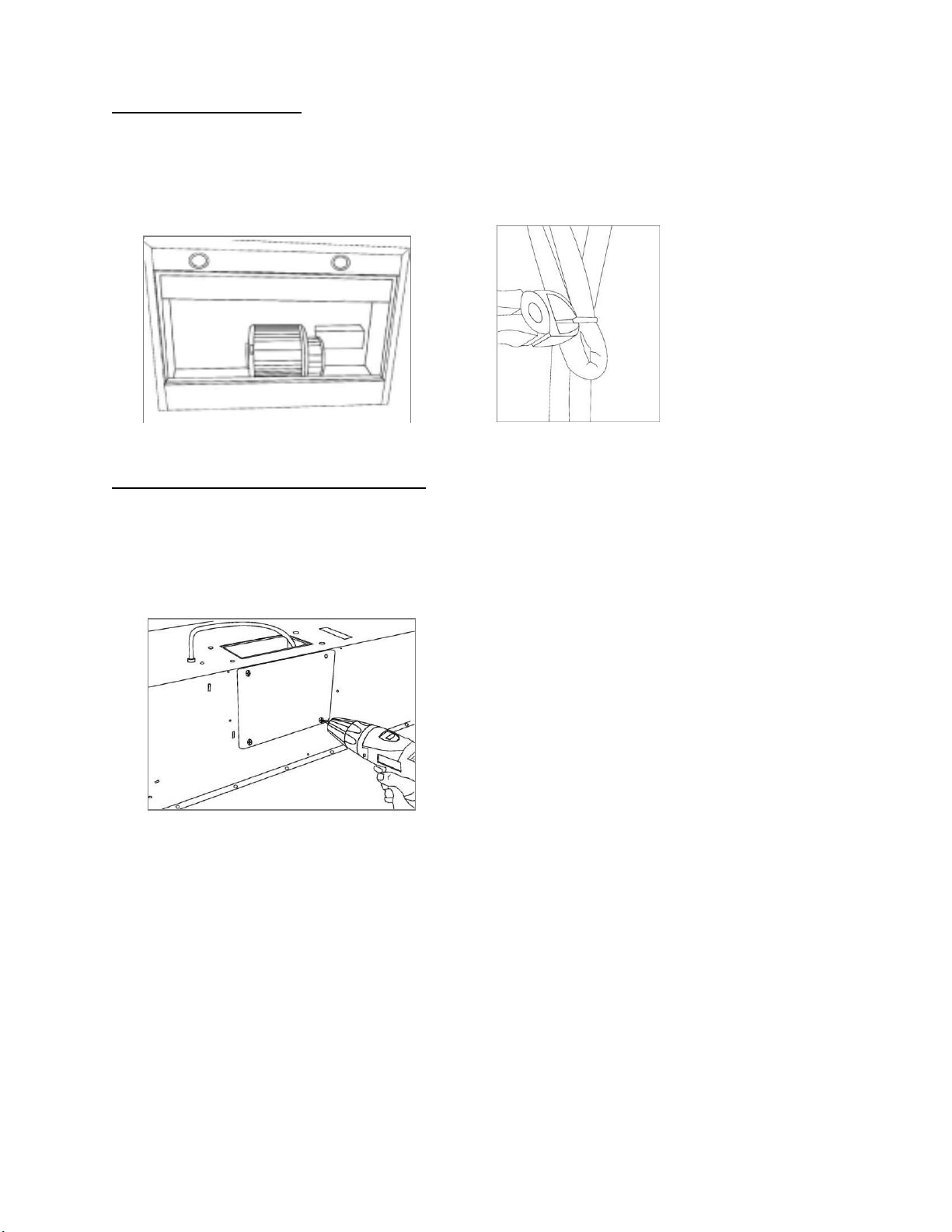
p 1: Prepare Range Hood
- Remove unit from packaging
- Position the unit on its back on a flat non abrasive surface - front facing you (See pic 3)
- Remove the 2 filters to allow access to the inside of the unit (See Pic 3)
- Cut tie wraps so wires are free to move and be relocated (See Pic 4)
Pic 3 Pic 4
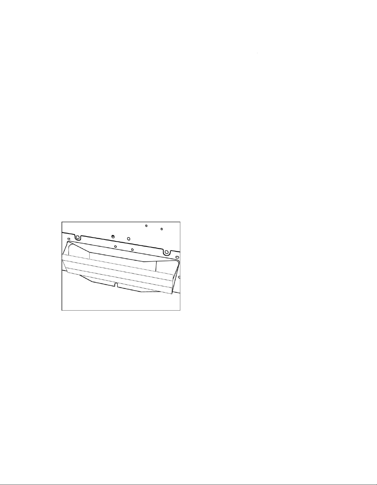
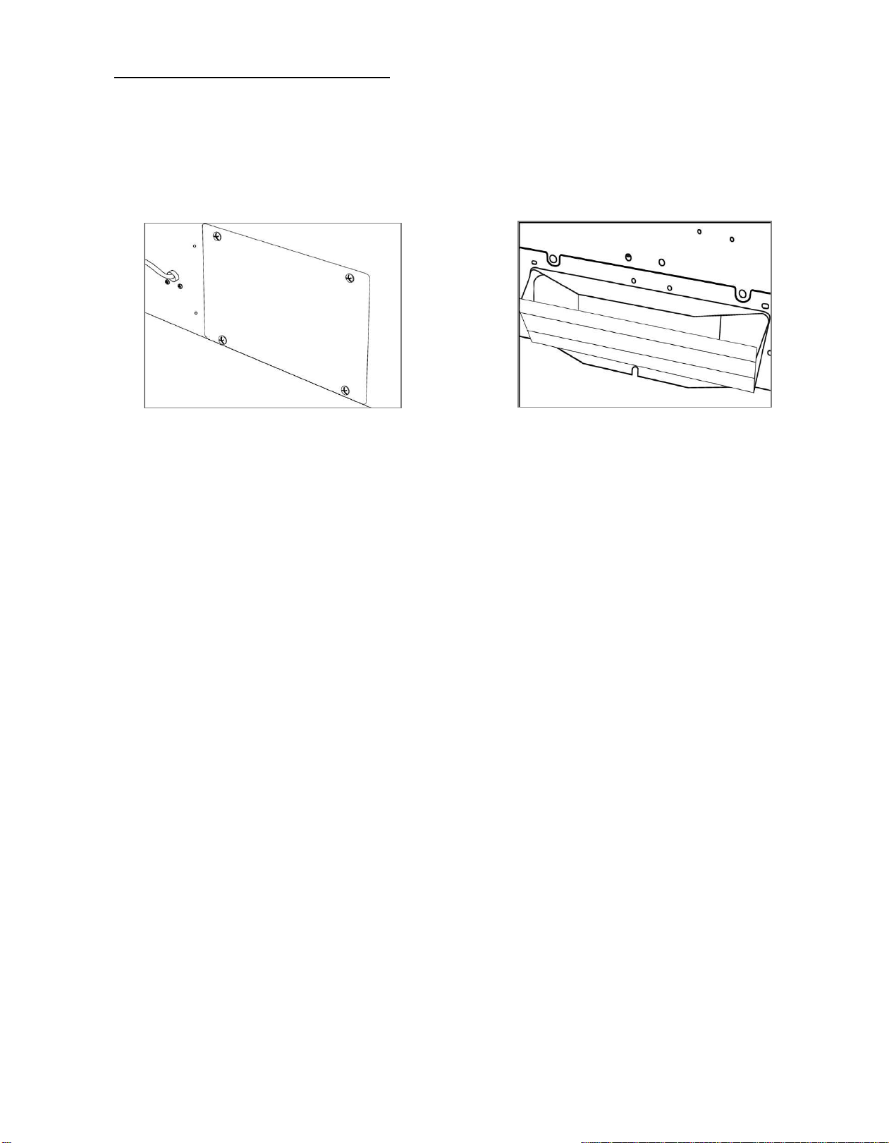
Step 2: Remove rear vent back plate (See Pic 5)
- Position the unit face down on a flat non abrasive surface - rear of product facing you
- Remove the back plate by removing the 4 screws
Pic 5
B-
8
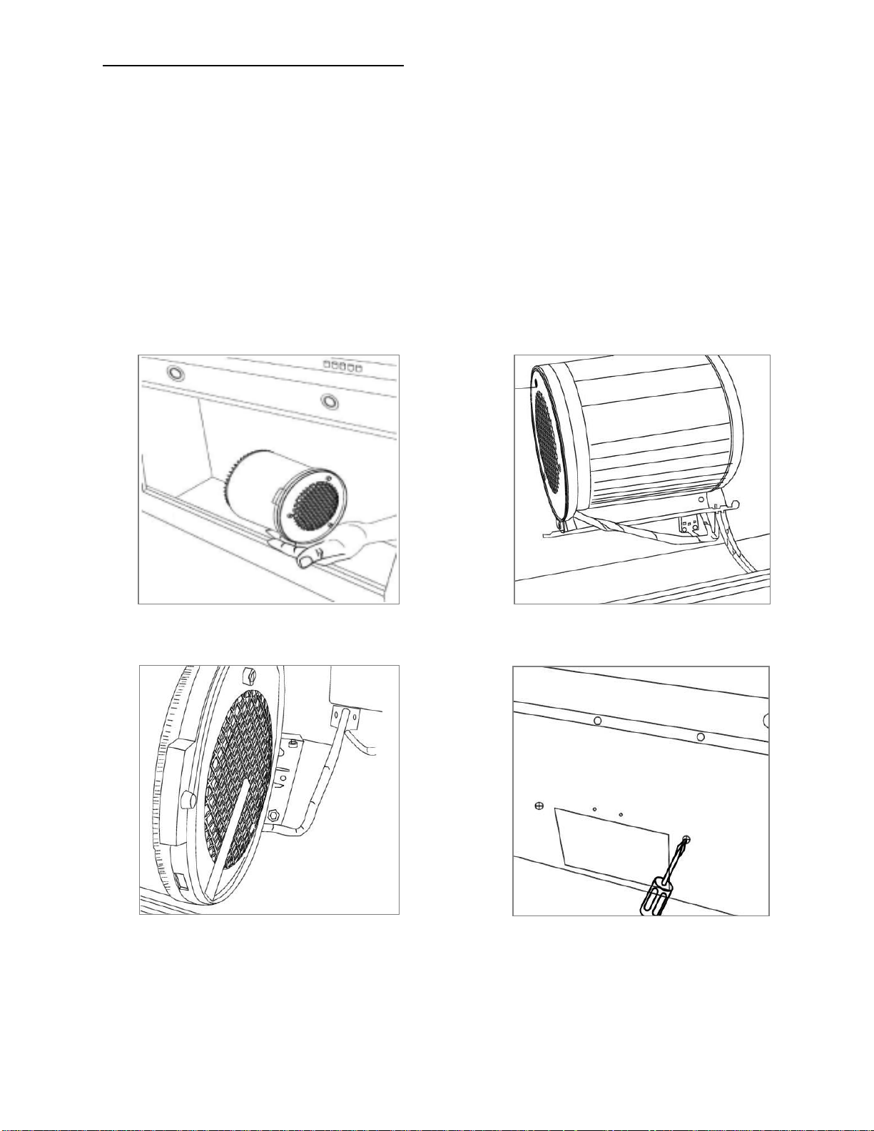
Step 3: Relocate motor exhaust at the rear of unit
- Position the unit on its back on a flat non abrasive surface – perpendicular to your working surface (See Pic
6)
- Place hand to hold motor in position and ensure weight of motor is well supported (See Pic 6)
o This will ensure screws don’t get bent or broken
- Remove 4 screws that hold motor in place on the top side of the hood
o Ensure the motor weight is well supported by your hand as the last screw in place may break under
the weight of the motor
- Once
the motor is set free from the hood, rotate motor clock wise to position venting outlet with rear
rectangular hole, ensuring that:
o Electric wire is located under the motor as you relocate the motor outlet (See Pic 7)
o Electric wire is not caught under the motor outlet (See Pic 8)
o 4 holes are aligned with screw holes at the rear
- Put unit upside down so the screw holes securing the motor are in a position facing you
- Install 4 screws to hold motor – Use a s
crew driver to perform operation – NOT
A DRILL as it may strip the
motor housing thread (See Pic 9)
Pic 6 Pic 7
Pic 8 Pic 9
9
Step 4: Install top vent plate and rear damper
- Re-install the plate removed in step 2 to block top venting hole
o Put plate in position and put in 4 screws from step 2 (see Pic 10)
- Install rectangular air damper outlet on the rear vent location (see Pic 11)
- Connect duct work to damper
- Use Duct Tape to ensure joint is sealed and air tight
Pic 10 Pic 11
;
;
;
;
.
(S
(S

.
7¼" (185 mm)
6½" (165 mm)
1¹/
8
" (28 mm)
7¼" (185 mm)
27 / " (708 mm)
7
8
9¼" (235 mm)
1½" (38 mm)
½" (90 mm)
27⅞" (708 mm)
4¼"
(108 mm)
11" (280 mm)
27⅞" (708 mm)

7¼" (185 mm)
6½" (165 mm)
1¹/8" (28 mm)
7¼" (185 mm)
9¼" (235 mm)
1½" (38 mm)
11" (280 mm)
4¼" (108 mm)
1¹/8" (28 mm)
7¼" (185 mm)
9¼" (235 mm)
1½" (38 mm)
27⅞" (708 mm)
27⅞" (708 mm)
top
.
12
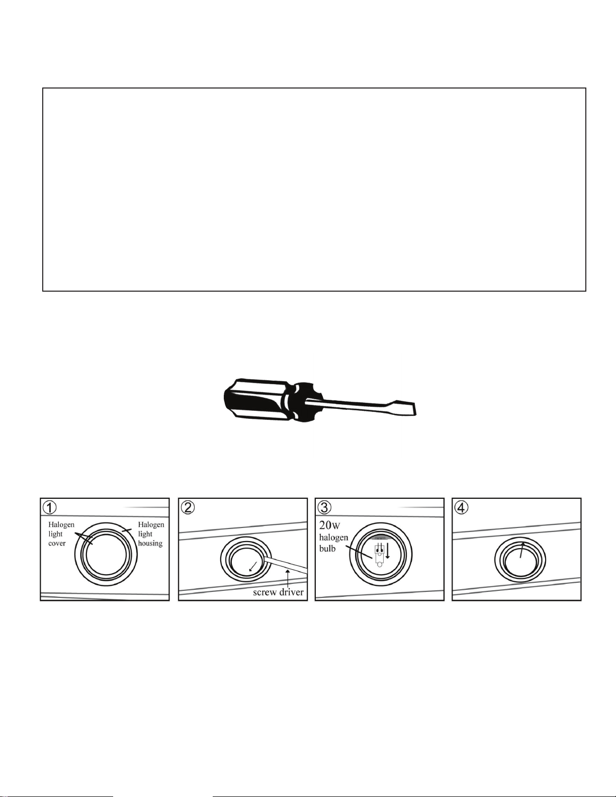
Replacing the light bulbs:
• This range hood uses halogen bulbs: 20W 12V type G4.
• Make sure the range hood is unplugged or turn OFF breaker.
• Place a flat-head screwdriver between light cover and housing to remove cover.
• Gently pull defective bulb straight out and discard
• Wear a cotton glove or use a cloth to handle the replacement bulb.
(DO NOT handle with bare fingers as this may shorten the life of the bulb).
Push gently but securely into light socket.
NOTE: DO NOT push too hard as bulb “legs” may break off.
• Replace light cover.
• Turn ON breaker and range hood to test for operation.