Loading ...
Loading ...
Loading ...
Installation
Installation
English26
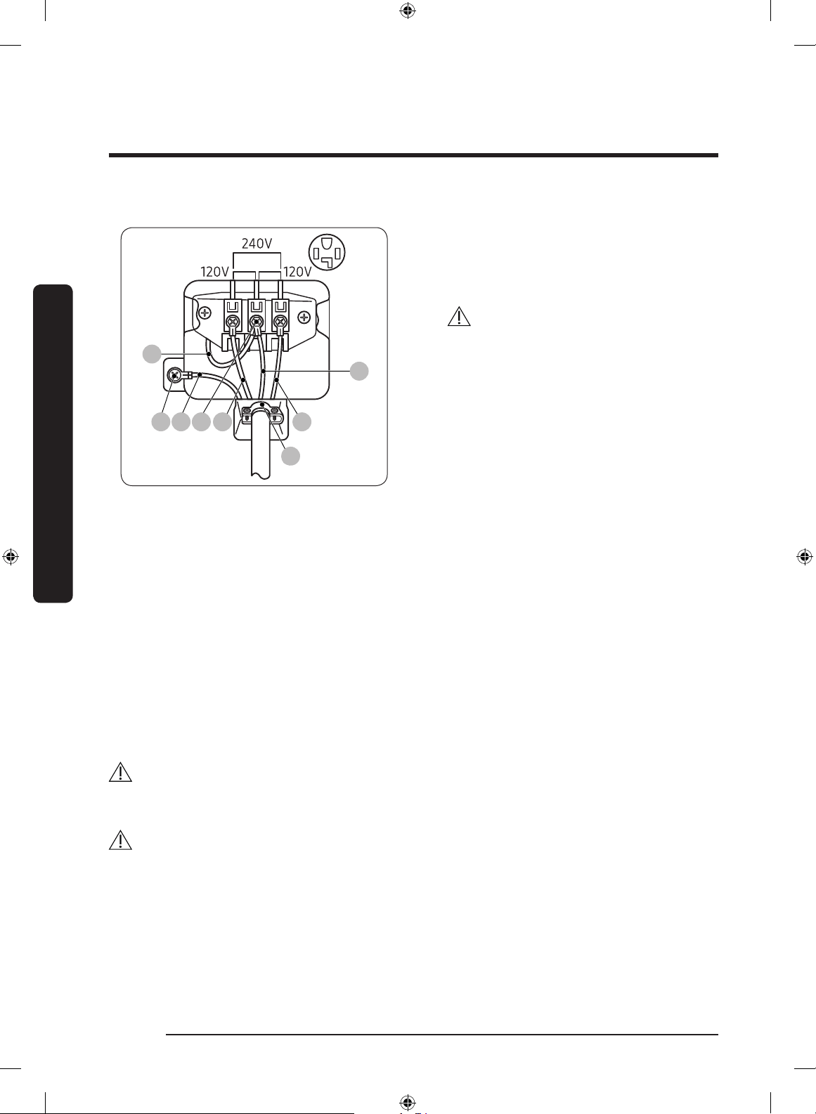
4-wire system
F
A B C L2 L1
D
E
A. External ground connector
B. Neutral grounding wire (white)
C. Center silver-colored terminal block
screw
D. Neutral wire (white or center wire)
E.
3
/
4
” (1.9 cm) UL-listed strain relief
F. Neutral wire (white or center wire)
1. Remove the external ground connector’s
screw, and connect the ground wire
(green or unwrapped) of the power cable
to the screw.
CAUTION
• To connect the ground wire to the
neutral position without contact A
(cabinet ground), contact a technician.
It is not user serviceable.
• Ring-type terminals are
recommended. If using strap
terminals, make sure they are
tightened.
2. Loosen or remove the screws from the
center terminal block.
3. Connect the neutral wire (white or
center wire) and ground wire (white) to
the center screw of the terminal block.
Tighten the screw.
4. Connect the other wires to the outer
terminal block screws. Tighten the
screws.
5. Tighten the strain relief screws.
6. Insert the tab of the terminal block cover
into the rear slot of the dryer. Secure the
cover with a hold-down screw.
CAUTION
Connect the power cord and check L1/L2/N voltage. If the voltage is low, it may not heat
properly. Review the “Electrical requirements” section on page 19 if needed.
WARNING
• All U.S. models are designed for a 3-wire system connection. The dryer frame is
grounded to the neutral conductor at the terminal block. A 4-wire system connection
is required for new or remodeled construction, mobile homes, or if local codes do not
permit grounding through neutral. If you use the 4-wire system, you cannot ground the
dryer frame to the neutral conductor at the terminal block.
• Remove the terminal block cover plate. Insert the power cord with a UL-listed strain
relief through the hole provided in the cabinet near the terminal block.
DV3000A(SEM)_DC68-03784P-00_EN.indd 26 2020-12-07 4:50:55
Loading ...
Loading ...
Loading ...