3511035556
¤
Included Wall Control MUST be installed prior to operation of this Garage
Door Operator
Safe-T-Beam
®
Safety Reverse System Must be installed to close door
SAVE THIS MANUAL FOR FUTURE REFERENCE
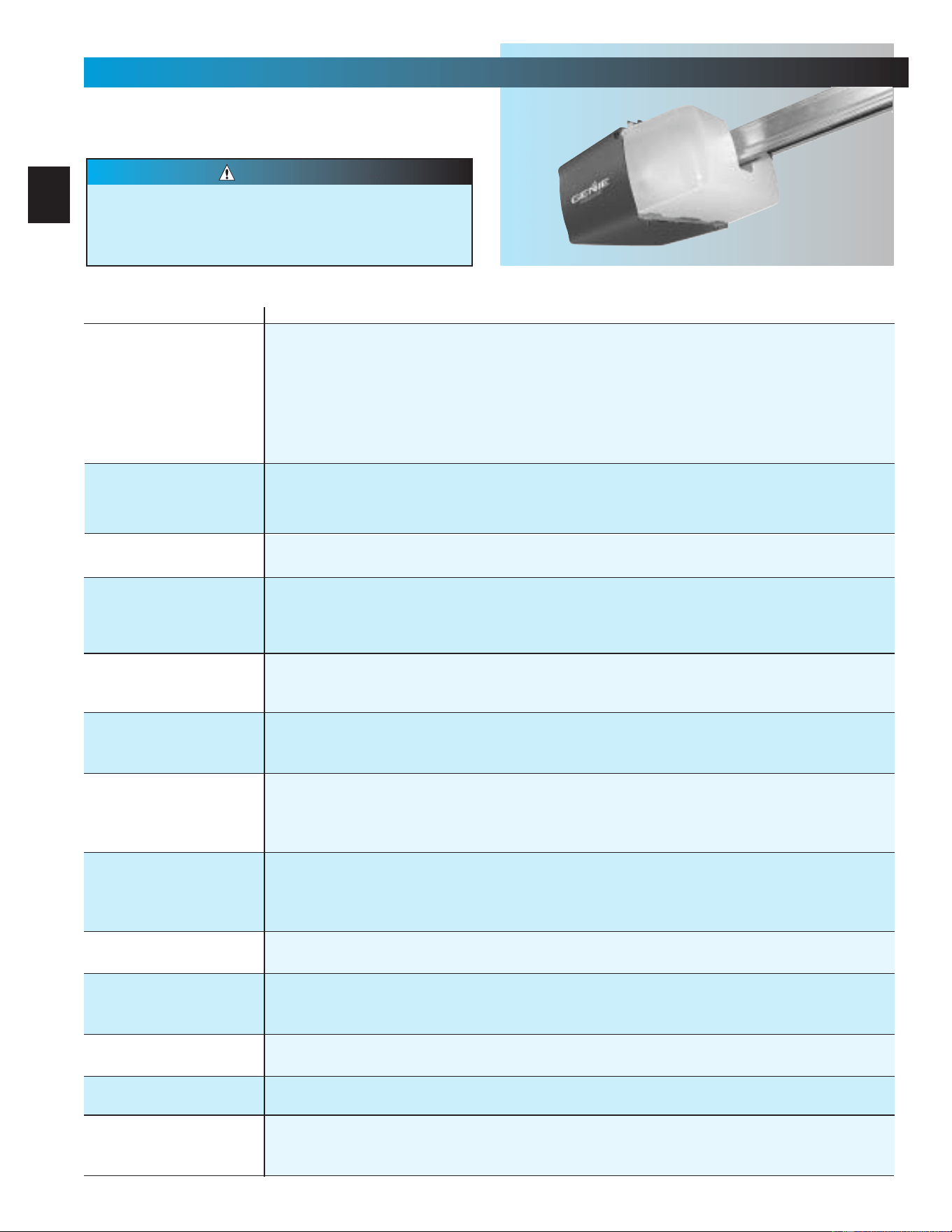
NOTE: Your Residential Operator comes with a Rail Assembly
which is standard for up to a 7 foot 6 inch high door. An extension
kit for an 8 foot high door is available.
®
For Answers and Assistance:
1.800.354.3643
or visit www.geniecompany.com
Series
IS, ISL, IC, H
Includes Remote Control
and SERIES II Electronics

2
Things to consider if you are planning to “do-it-yourself.”
Whether you are replacing an existing garage door operator or installing an operator in your
garage for the first time, there are some pre-installation issues which need to be addressed.
They are as follows:
The Genie Company recommends that you read and fully understand all
information and instructions contained herein before choosing a “do-it-yourself ”
installation. Any questions should be directed to the Genie Company or an authorized
Genie Dealer.
6
To avoid damage to your door and/or
operator, make sure you disable any door
locks prior to installing your operator
.
PRE-INSTALLATION CHECK LIST
FOR HELP-1.800.354.3643 OR GENIECOMPANY.COM
1
Check your ceiling where the power
head of your new unit will be mounted.
Plan how you will be mounting the power head.
It is possible that ceiling joists may not be in the
exact position needed with respect to the garage
door operator. It may be necessary to add an
additional bracket and
fasteners (not included
with your new door operator kit).
2
Check the wall directly above the garage
door
. The door operator’s header bracket
must be securely fastened to this wall. Ensure
that the structure will provide a strong mounting
location.
3
Check to see if the mounting location
for the Safe-T-Beam
®
System (STB) is
clear from obstruction and has a wood
surface available for attaching the STB brack-
ets
. The brackets may be attached to concrete if
necessary but extra tools and special fasteners
(not supplied) will be required.
NOTE: 1-1/2" STB bracket adapters are
available through your local Genie Dealer.
4
Is your garage door made of
light-weight steel, aluminum, fiberglass
or glass panels
? Additional support bracing
must be added to these type doors. If this is the
case, please contact the door distributor or
manufacturer so that they can furnish you with a
“bracing kit.”
7
Ensure that your door is properly balanced
and moving freely. SEE WARNING BELOW.
If your door sticks, binds, or is out of
balance, have it adjusted by a professional.
Door springs, cables, pulleys, brackets and
associated hardware are under extreme
tension and can cause serious injury or
death.
WARNING
(
The issue numbers below refer to the circled numbers in the illustrations on page 3.
)
8
(NOT SHOWN) If your garage does not have
a separate entry door, you should consider
an emergency release kit
(
GER-2
)
for installation
on your garage door. See page C at the center of
this manual.
DO NOT USE AN EXTENSION CORD!
Extension cords can cause dangerous
overheating conditions.
DO NOT USE A PORTABLE GENERATOR!
This product is designed to operate on
standard house current. Do not use
alternate power supplies.
WARNING
5
You need a 110-120 Volt power supply
available
. The outlet should be no more than
3 feet from the power head once it is mounted. (The
cord is 4 ft. in length.) SEE WARNING BELOW.
HomeLink® is a universal
transceiver (a combined
transmitter and receiver), that provides a
convenient way to replace up to three hand-held
radio-frequency (RF) transmitters used to
activate devices such as gate operators, garage
door openers, entry door locks, security systems
and even home lighting. Additional HomeLink
®
information can be found at: www.homelink.com
or by calling 1.800.355.3515
.
3
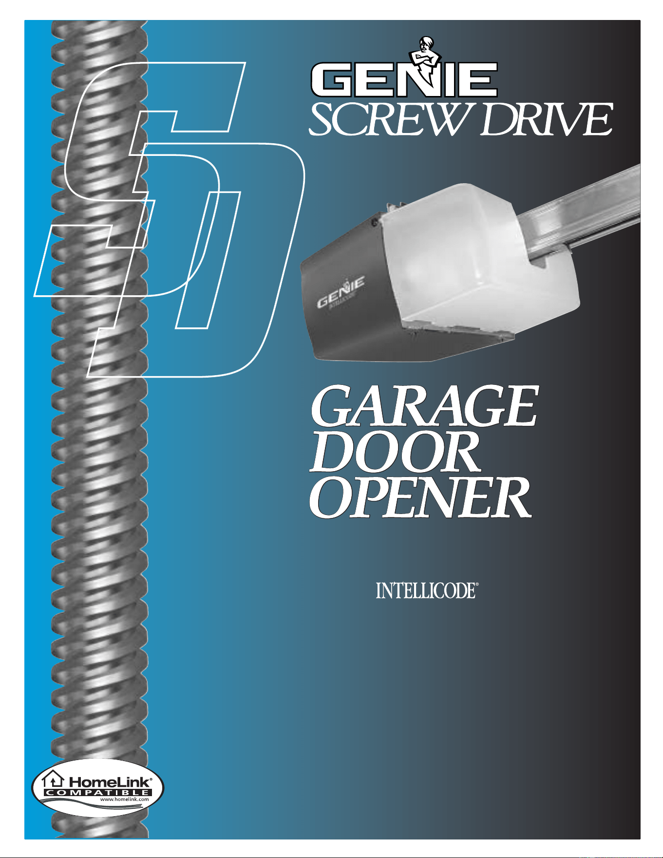
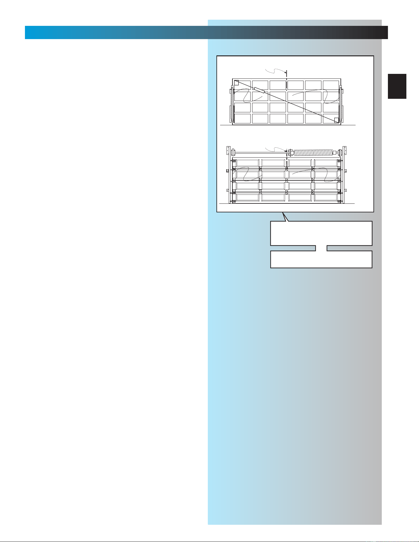
TYPICAL SECTIONAL DOOR INSTALLATION
5
TYPICAL
SUPPORT
BRACKET
EXTENSION SPRING
OR
TORSION SPRING
SAFE-T-BEAM
®
BRACES
ADDED
HEADER BRACKET
MOUNTING BOARD
36” POWER CORD
TO
120V GROUNDED
OUTLET
6
4
3
1
2
3
7
SECTIONAL DOOR
1-PIECE DOOR
TYPICAL 1-PIECE
DOOR INSTALLATION

4
Safe-T-Beam
®
(STB) Non-Contact Reversing System
Places an invisible beam across door opening that reverses the door during down travel to the fully open
position if anything passes through beam.
Safe-T-Reverse
®
Contact Reversing System
Automatically stops and reverses a closing door within 2 seconds of contact with an object.
Safe-T-Stop
®
Timed Reversed System
Automatically opens a closing door, if door does not close within 30 seconds.
Force Guard
®
Control
Used to set the force required for opening and closing door. For maximum safety, set the minimum force
required to fully open and close door.
Automatic Lighting System
Two light bulbs up to 60 Watts max. each are used for safer entries and exits. The light turns on when door is
activated and automatically turns off 4.5 minutes later.
Manual Emergency Release
Allows the garage door to be opened or closed manually for emergencies or maintenance.
SAFETY FEATURES
(
varies by model
)
TABLE OF CONTENTS
SECTION PAGE
PRE-INSTALLATION CHECK LIST . . . . . . . . . . . . . . . . 2-3
TOOLS REQUIRED . . . . . . . . . . . . . . . . . . . . . . . . . . . . . . 4
SAFETY FEATURES . . . . . . . . . . . . . . . . . . . . . . . . . . . . . . . . 4
OPERATIONAL FEATURES . . . . . . . . . . . . . . . . . . . . . . . . . . 5
PARTS LISTS AND ILLUSTRATIONS . . . . . . . . . . . . . . . . . 5-8
POWER HEAD . . . . . . . . . . . . . . . . . . . . . . . . . . . . . . . . . . 5
ONE-PIECE RAIL . . . . . . . . . . . . . . . . . . . . . . . . . . . . . . . . 6
THREE-PIECE RAIL . . . . . . . . . . . . . . . . . . . . . . . . . . . . . . 7
FASTENERS AND ACCESSORIES . . . . . . . . . . . . . . . . . . 8
SAFETY INFORMATION . . . . . . . . . . . . . . . . . . . . . . . . . . . . . . 9
PRE-INSTALLATION WARNING . . . . . . . . . . . . . . . . . . . . . . . . 9
1MAIN ASSEMBLY . . . . . . . . . . . . . . . . . . . . . . . . . 10-14
2INSTALLATION . . . . . . . . . . . . . . . . . . . . . . . . . . . 15-21
3 SAFE-T-BEAM
®
. . . . . . . . . . . . . . . . . . . . . . . . . . . 22-23
4WALL CONTROL . . . . . . . . . . . . . . . . . . . . . . . . . . 24-25
5 LIGHT & LIGHT LENS. . . . . . . . . . . . . . . . . . . . . . . . . 25
6 CONNECTING POWER . . . . . . . . . . . . . . . . . . . . . . . . 26
7 SETTINGS. . . . . . . . . . . . . . . . . . . . . . . . . . . . . . . . 27-28
CONTACT REVERSE. . . . . . . . . . . . . . . . . . . . . . . 28
8BATTERY & VISOR CLIP. . . . . . . . . . . . . . . . . . . . . . . 28
9PROGRAMMING REMOTE CONTROLS . . . . . . . . . . 29
TRANSMITTER COMPLIANCE STATEMENT . . . . . . . . . . . . 30
IMPORTANT SAFETY INSTRUCTIONS . . . . . . . . . . . . . . . . . 30
10 MAINTENANCE & TROUBLESHOOTING . . . . . . . 31-32
11 WIRING DIAGRAM . . . . . . . . . . . . . . . . . . . . . . . . . . . . A
WARRANTY B
ACCESSORIES ORDER FORM . . . . . . . . . . . . . . . . . . . . . . . . C
RECOMMENDED TOOLS
5/ 32" Drill Bit
7/16" and 9/16" Sockets
Step ladder
Drill
Ratchet
Carpenter’s level
Pencil
Tape measure
Wire strippers
Phillips screwdriver
Adjustable wrench
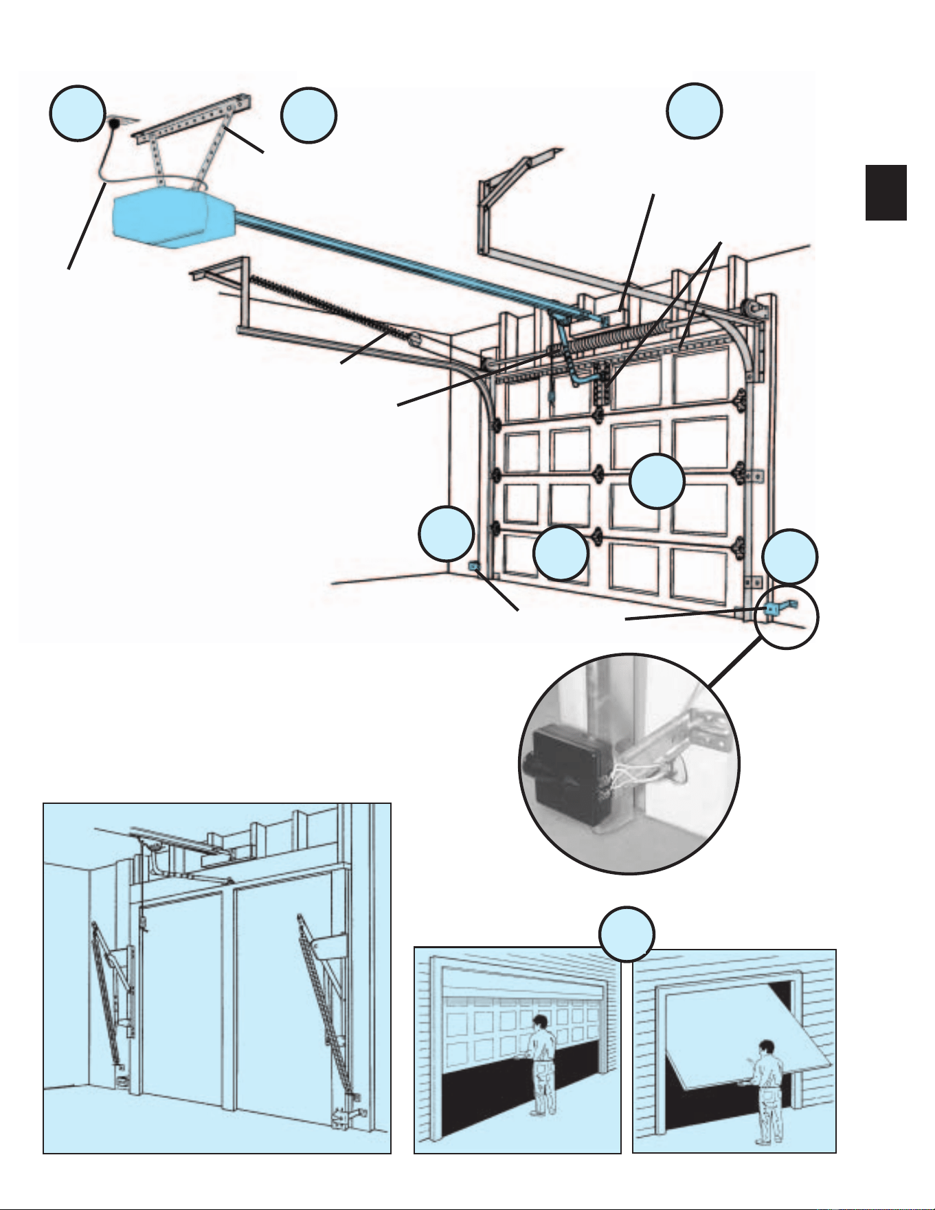
5
POWER HEAD EXPLODED VIEW
FOR HELP-1.800.354.3643 OR GENIECOMPANY.COM
Power Head Assembly
[
1
]
Item Part Name
1Power Head Assembly
ACover (By Series/Model)
B Front Plate Assembly
C Light Socket
D Motor Parts
E Receiver Assembly
F Capacitor (By Series/Model)
G Opto Wheel
HOpto-Luctor Assembly
J Sequencer Assembly
KCircuit Board Bracket
LTransformer
POWER HEAD PARTS LIST
41
F
E
N
B
5
C
49
42
45
39
4
L
M
K
H
N
J
A
D
Item Part Name
MTerminal Strip
NNo. 8-32 x 1/2" Hex Washer Head Screw
PNo. 8-32 x 3/8" Slot Hex Washer Head Screw
RCapacitor Isolator
45 Bumper
4 1/4-20 Shoulder Bolt
5 1/4" Flange Nut
39 Coupler
41 No. 8-32 x 3/8" Phillips Hex Head Screw
42 No. 8-32 x 3/8" Phillips Pan Head Screw
48 Mounting Straps
49 Light Lens
OPERATIONAL FEATURES
INTELLICODE
®
Access Security System
Improves security of door operator by continuously changing the access code each time the remote control is
used. The door operator responds to each new code only once. An access code copied from a working system
and tried again will not control the door operator.
INTELLICODE
®
1-Button Remote Control
Controls door operator by allowing the garage door to be opened and closed remotely.
INTELLICODE
®
Multi-Button Remote Control
Operates multiple Intellicode
®
equipped door operators.
Lighted Wall Button (some models)
Operates door operator from inside garage. DO NOT use with lighted wall console.
Wall Console (some models)
Works like a lighted wall button but includes a Vacation Lock Switch that disables all controls. LED indicator
shows whether system is powered, locked or unlocked. Makes console easy to find in dark. Controls door
opener from inside garage. Independent light control allows convenient manual control of the Automatic Lighting
System. DO NOT use with lighted wall button.
NOTE: All items may not be supplied with your garage door operator.
48
G
P
R
6
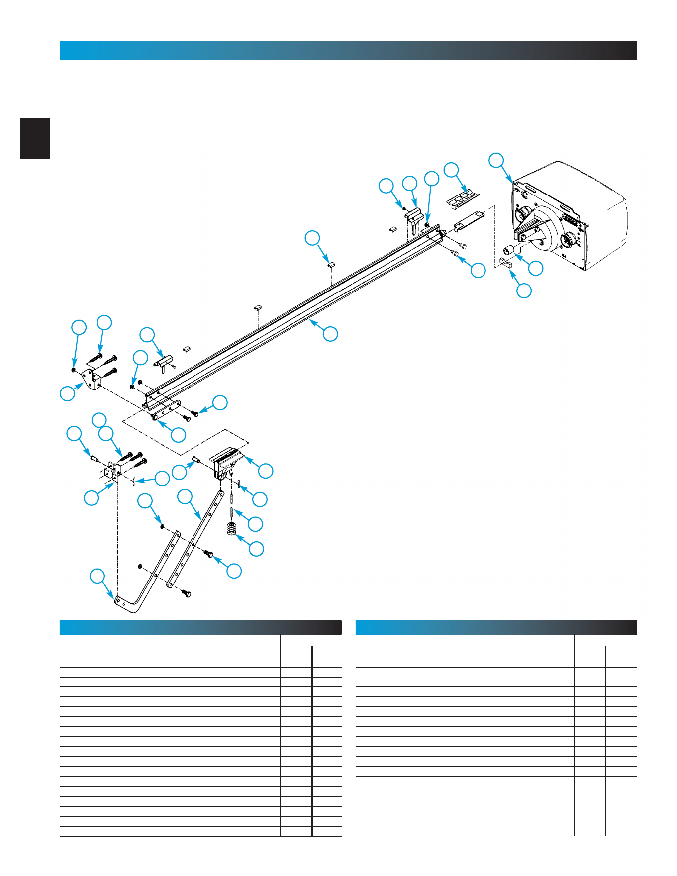
1-PIECE RAIL HARDWARE EXPLODED VIEW
FOR HELP-1.800.354.3643 OR GENIECOMPANY.COM
1-Piece Rail & Screw Assembly
[
2
]
NOTE:The operator will not function properly unless the Safe-T-Beam
®
sensors are installed and the force controls adjusted.
16
6
1
44
15 B
22
9
2224
28
26
23
9
10
25
17
18
27
46
15 A
4
39
45
5
47
25
24
13
Item Part Name
Parts Required
1 Piece 3-Piece
1 Power Head Assembly (See page 5) 1 1
2 Rail Assembly (1 piece) 1
3 Rail Assembly (3 piece) 1
3A First Rail Section 1
3B Middle Rail Section 1
3C End Rail Section 1
4 1/4-20 Hex Hd Shoulder Bolt 2 2
5 1/4"-20 Hex Flange Nut 2 2
6 Carriage Stop 1 1
7 Rail Clamps 4
8 5/16" Hex Shoulder Bolt 8
9 5/16" Hex Flange Nut 5 13
10 Carriage Assembly 1 1
11 Collar 2
12 Retaining Clip 2
13 Rail Strap 1 1
15A Open Limit Switch Assembly (Grey) 1 1
PARTS LIST
Item Part Name
Parts Required
1 Piece 3-Piece
15B Close Limit Switch Assembly (Brown) 1 1
16 No. 8-32 x 3/8" Hex Head Screw 2 2
17 Emergency Release Cord 1 1
18 Emergency Release Knob 1 1
19 Emergency Release Tag 1 1
20 Header Bracket 1 1
21 Door Bracket 1 1
22 1/4" x 2" Lag Screw 8 8
23 Straight Door Arm 1 1
24 Clevis Pin 2 2
25 Cotter Pin 2 2
26 Curved Door Arm 1 1
27 3/8" x 7/8" Hex Head Bolt 2 2
28 3/8" Hex Flange Nut 2 2
29 Wire 95ft 95ft
30 Insulated Staple 30 30
31 Wall Button varies varies
PARTS LIST
20
21
2
~
~
~
~
~
~
~
~
OR
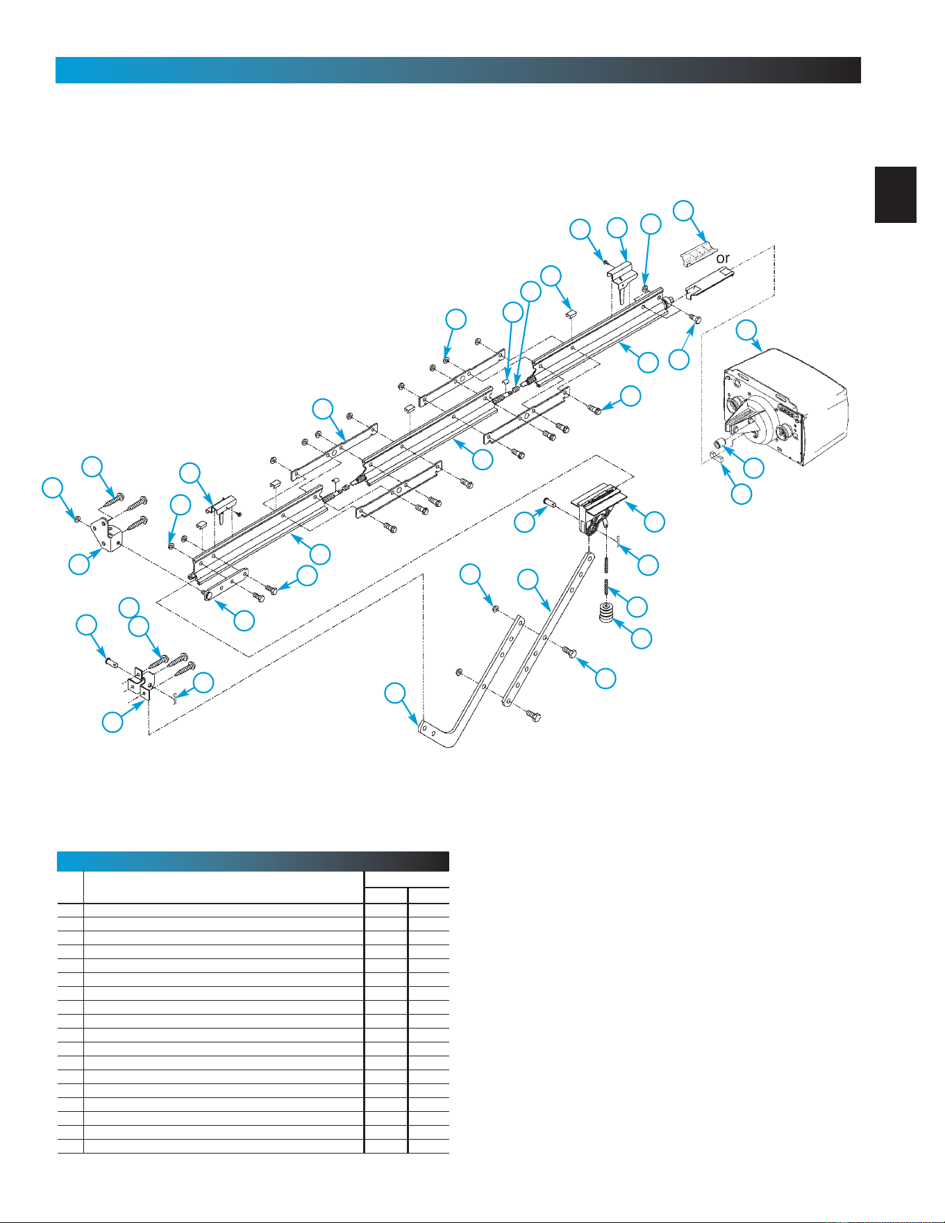
7
3-PIECE RAIL HARDWARE EXPLODED VIEW
FOR HELP-1.800.354.3643 OR GENIECOMPANY.COM
3-Piece Rail & Screw Assembly
[
3
]
NOTE: The operator will not function unless the Safe-T-Beam
®
system is
installed and the force controls are properly set.
16
6
1
44
15 B
22
9
22
24
28
26
23
9
10
25
17
18
27
46
15 A
4
39
45
5
47
25
24
9
8
7
11
12
3A
3B
3C
13
Item Part Name
Parts Required
1 Piece 3-Piece
33 Wall Console varies varies
34 #6 x 1-1/4” Pan Head Screw 2 2
35 Entrapment WARNING Label 1 1
36 Safe-T-Beam (STB) System Sensor (Green LED) 1 1
37 Safe-T-Beam (STB) System Source (Red LED) 1 1
38 Safe-T-Beam (STB) System Bracket 2 2
39 Coupler 1 1
40 No. 10 x 11/4" Phillips Hex Head Screw 4 4
41 #8 x 3/8” Hex Head Screw 4 4
42 #8 x 3/8” Pan Head Screw 2 2
43 Safety & Maintenance Guide 1 1
44 Wire Clip 4 4
45 Bumper 1 1
46 5/16" x 3/4" Hex Head Bolt 5 5
47 1/4-20 x 3/4” Self-tapping Screw 3 3
48 Mounting Straps 2
49 Light Lens (Shown on page 5) 1 1
50 Remote Control varies varies
PARTS LIST
20
21
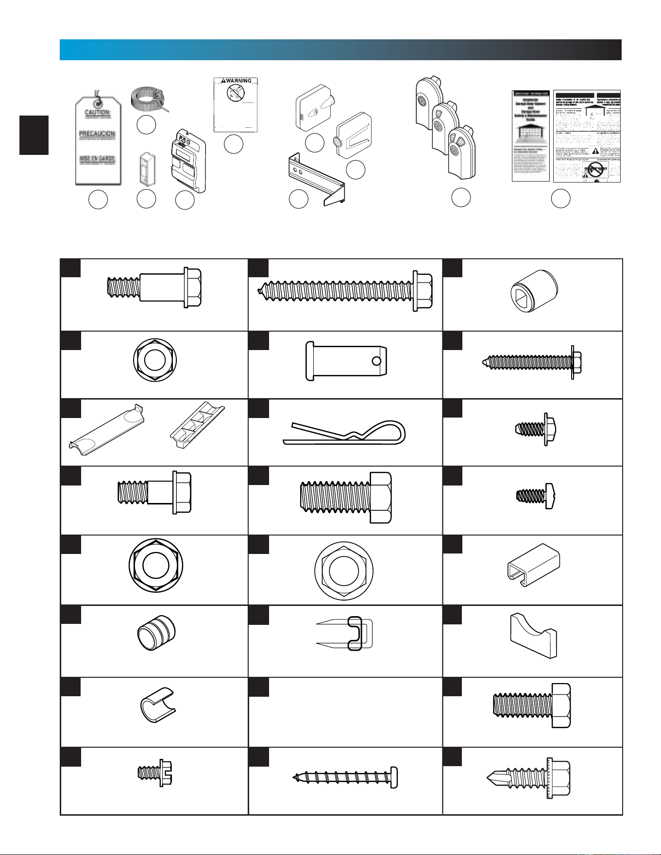
8
NOTE: Accessories vary by model.
FASTENERS - Shown full size. See Parts List for description.
35
19
43
31
29
38
37
36
Cotter pin
Clevis pin
33
4
5
8
9
11
6
12
16
22
24
25
27
28
39
34
PARTS IDENTIFICATION FOR HELP-1.800.354.3643 OR GENIECOMPANY.COM
45
46
47
32
remotes
vary
by model
Rubber bumper
1/4" x 2" Lag screw
5/16" Flange nut
3/8" Hex head bolt
3/8" Nut
#10 x 1-1/4" Phillips hex head screw
1/4" Flange nut
Insulated staple
Coupler
#8-32 x 3/8" Hex head screw
Collar
5/16" Shoulder bolt w/flange
5/16" x 3/4" Hex head bolt
1/4" Shoulder bolt w/flange
1/4"-20 Self-drilling screw
#6 x 1-1/4" Pan head screw
42
44
41
Clip
30
40
Wire clip
#8 x 3/8" Pan head screw
#8 x3/8" Hex flange head screw
Carriage stop (not to scale)
50
OR
9
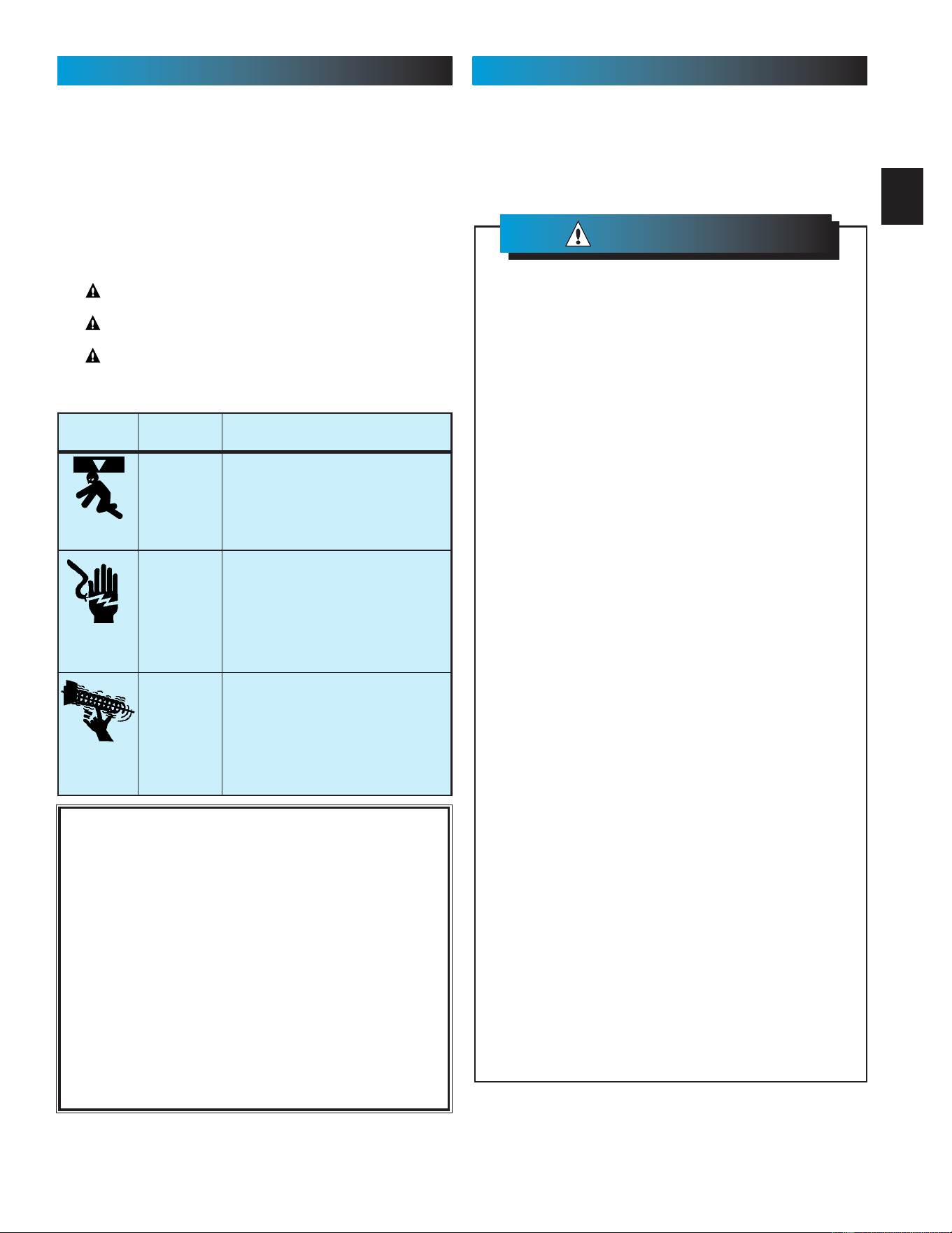
WARNING
:
Garage doors are large, heavy objects that move with the help of springs
under high tension and electric motors. Since moving objects, springs under
tension, and electric motors can cause injuries, your safety and the safety of
others depend on you reading the information in this manual. If you have
questions or do not understand the information presented, call your nearest
service representative.
In this section and those that follow, the words Danger, Warning, and
Caution are used to emphasize important safety information.
The word:
DANGER means that severe injury or death will result from failure
to follow instructions.
WARNING means that severe injury or death can result from failure
to follow instructions.
CAUTION means that property damage or injury can result from
failure to follow instruction.
The word NOTE is used to indicate important steps to be followed
or important considerations.
OVERVIEW OF
POTENTIAL HAZARDS
POTENTIAL
HAZARD
EFFECT PREVENTION
Keep people clear of opening while door is
moving.
Do Not allow children to play with the door
operator.
Do Not operate a door that jams or one that
has a broken spring.
MOVING
DOOR
WARNING:
Can Cause
Serious Injury
or Death
Turn off power before removing operator cover.
When replacing cover, make sure wires are not
pinched or near moving parts.
Operator must be properly grounded.
ELECTRICAL
SHOCK
WARNING:
Can Cause
Serious Injury
or Death
Do Not try to remove, repair or adjust springs
or anything to which door spring parts are
fastened, such as, wood blocks, steel
brackets, cables or other like items.
Repairs and adjustments must be made by a
trained service person using proper tools and
instructions.
HIGH
SPRING
TENSION
WARNING:
Can Cause
Serious Injury
or Death
IMPORTANT
INSTALLATION
INSTRUCTIONS
To reduce the risk of
severe injury or death:
WARNING
:
SAFETY INFORMATION PRE-INSTALLATION WARNING
SAVE THESE INSTRUCTIONS
Visit our website at:
www.geniecompany.com
FILL THIS IN AT TIME OF INSTALLATION FOR YOUR OWN
RECORDS, SO THAT IT WILL
BE AVAILABLE IF YOU EVER NEED TO CALL US.
Date Purchased _____/_____/_____
Serial Number _____/____/_______________________________
Operator Model _______________________________________
Dealer Name __________________________________________
Dealer Address _______________________________________
City _________________________________________________
State ________________________________________________
Zip _____________________
WK YY PI
MM DD YY
(See Fig. 1-1)
1. READ AND FOLLOW ALL SAFETY,
INSTALLATION AND OPERATION
INSTRUCTIONS. If you have any questions
or do not understand an instruction, call your
service representative.
2. Do Not install Opener on an improperly
balanced door. An improperly balanced
door may cause severe injury. Repairs and
adjustments to cables, spring assemblies,
and other hardware must be made by a
trained service person using proper tools
and instructions.
3. Remove all handles and ropes, and
disable all locks connected to the door
before installing the Opener.
4. Install door Opener 7' or more above
the floor. Mount the emergency release
knob 6' above the floor.
5. Do Not connect the Opener to the
power source until instructed to do so.
6. Locate the Wall Control:
• Within sight of the garage door.
• At a minimum height of 5', so small
children cannot reach it.
• Away from all moving parts of the
garage door.
7. Install the entrapment WARNING label
next to the wall button or console. Install
the emergency release tag on the
emergency release.
8. The operator must reverse when the door
contacts a 1
1
/
2
" high object on the floor at
the center of the doorway. This is the size of
a 2” x 4” board laid flat.
NOTE: Please keep original or photocopy of your
sales receipt with this manual for future reference
should service ever be required.
10
SECT 1—MAIN ASSEMBLY
FOR HELP-1.800.354.3643 OR GENIECOMPANY.COM
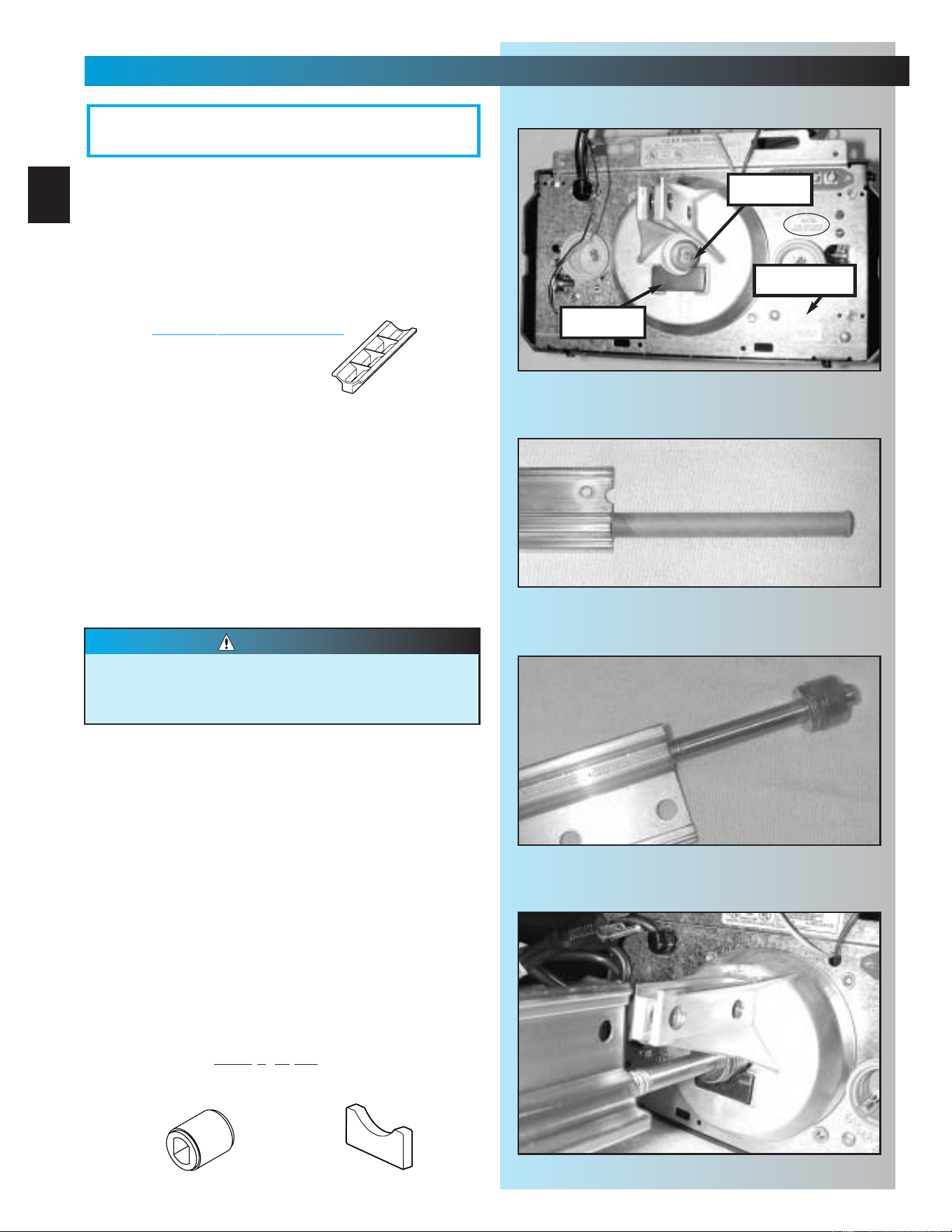
1. Set power head so that front panel (with end
of shaft and rail attachment flange) is facing up.
Fig. 1-1.
NOTE: If you have this type Carriage Stop, skip
Step 2. DO
NOT install Bumber.
2. Install bumper [45].
•Peel protective paper from glue side
of bumper.
• Stick bumper into position as shown.
Fig. 1-1.
3. Install coupler [39].
• Place coupler over end of shaft.
•Turn it as needed until it engages with shaft.
(It will drop down over end of shaft and will
no longer turn freely. Fig. 1-1.
4. Set power head on its bottom. Fig. 1-4.
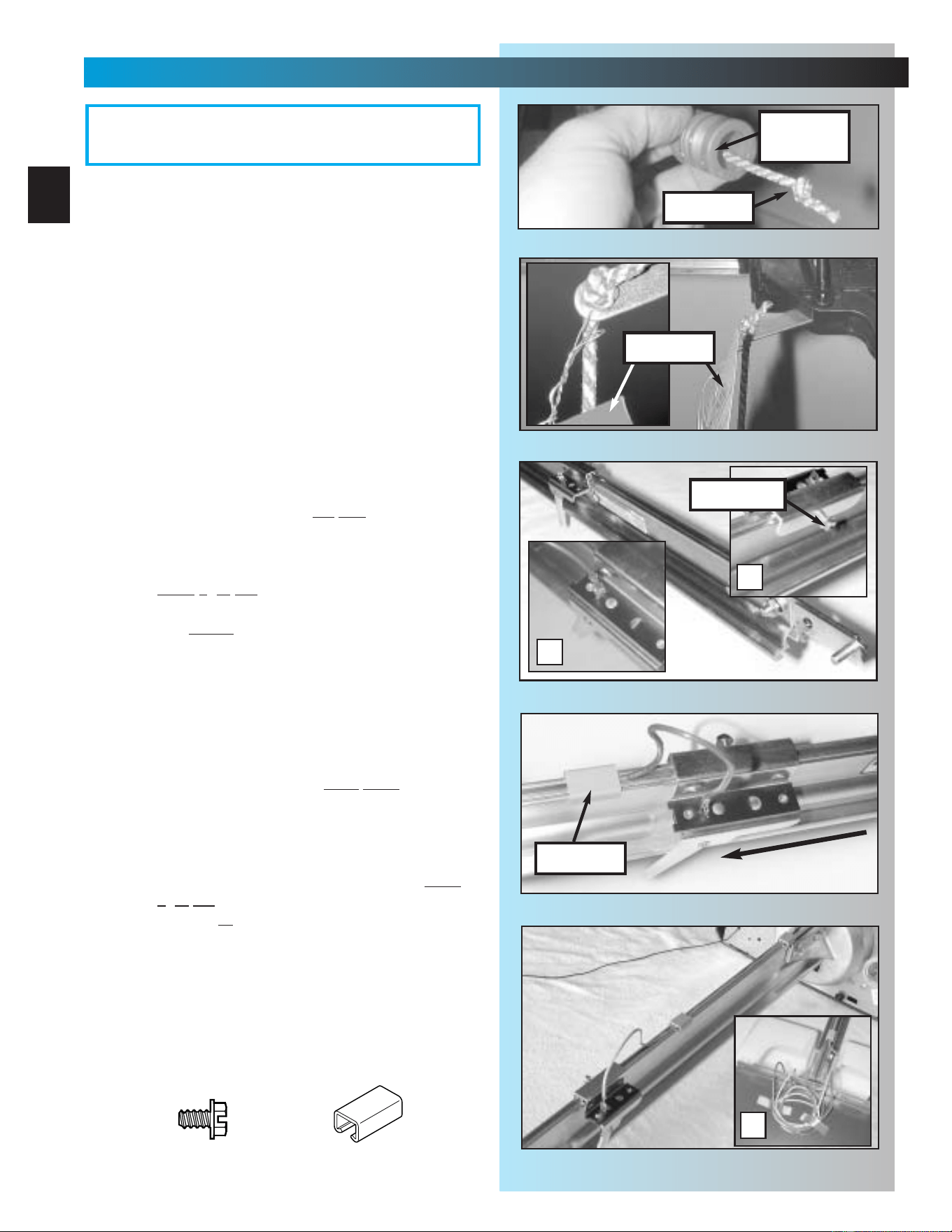
5. Attach 1-piece rail or “first” rail section[3A]
of 3-piece rail to power head.
• (3-piece only)Select “first” rail section. (It has
protective cardboard sleeve over end of
screw.) Fig. 1-2.
• (3-piece only) Remove cardboard sleeve.
• Slide end of screw out about 5 inches.
Fig. 1-3.
• Place bearing end of screw against coupler.
Fig. 1-4.
•Turn screw until it engages with coupler.
• Slide rail section into rail attachment flange
until holes in rail match up with holes
in flange.
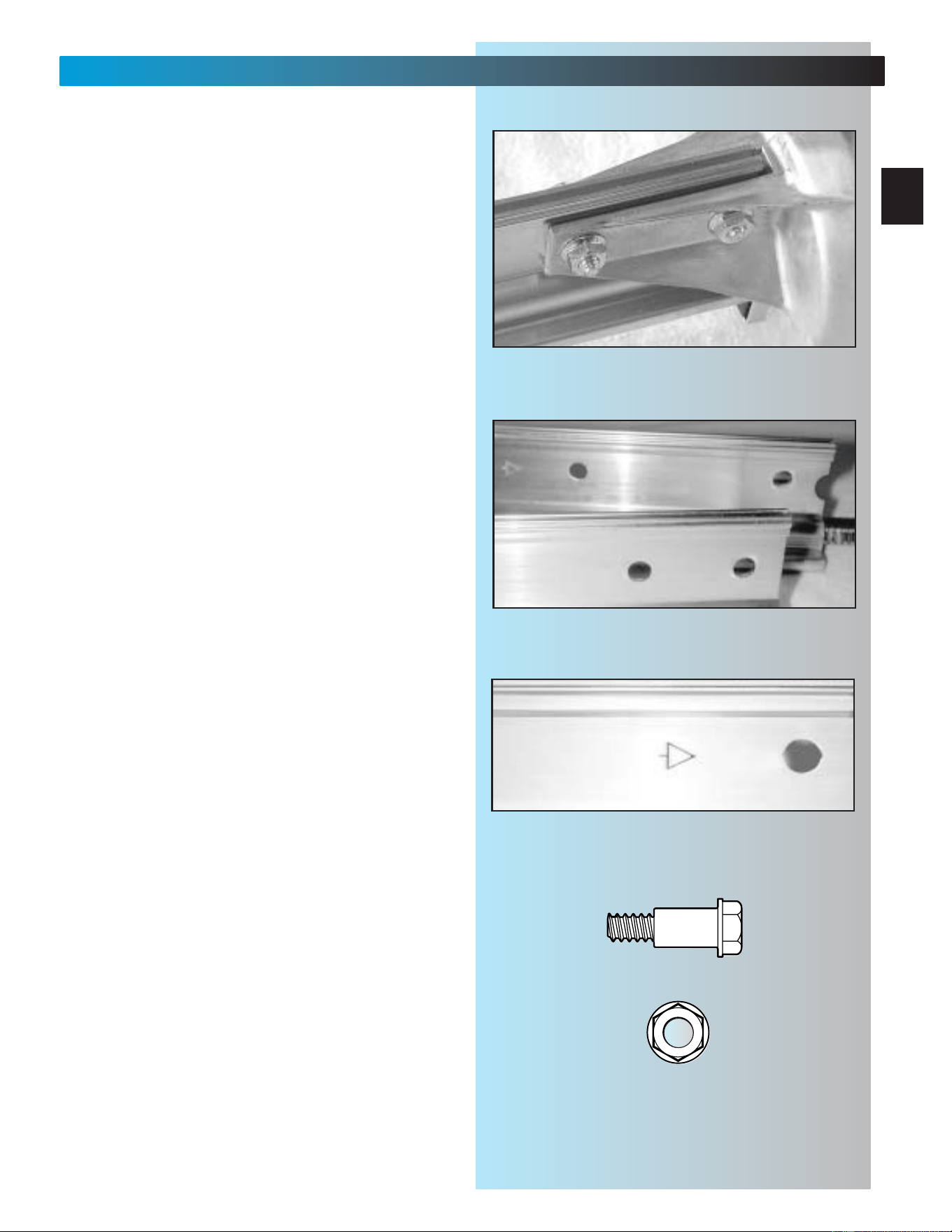
• Secure “first” rail section with 2 bolts [4] and
2 nuts [5], hand
tight only. Fig. 1-5.
• For 1-piece rail, skip to step 8.
bumper
coupler
Fig. 1-1
Fig. 1-2
Fig. 1-3
Fig. 1-4
Drive screws can slide out of rail sections.
Keep rail sections level until operator is
fully assembled.
CAUTION
NOTE: 3-piece rail assembly is for doors up to
and including 7 feet 6 inches high. An extension
for 8 feet doors is available.
OPEN BLUE PARTS BAG
Rubber bumper
Coupler
[
39
]
[
45
]
serial no.
11
MAIN ASSEMBLY
FOR HELP-1.800.354.3643 OR GENIECOMPANY.COM
6. Attach “middle” rail section [3B].
• Select “middle” rail section. (This section
looks identical on both ends with each set of
holes being about 4 inches apart.) Fig. 1-6.
•Find arrows stamped into side of rail.
Fig. 1-7.
• Align rail so arrows point away from
power head.
• Slide screw toward power head so it sticks
out end of rail section about 2 inches.
Fig. 1-5
Fig. 1-6
Fig. 1-7
1/4" Flange nut
1/4" Shoulder bolt w/flange
[
4
]
[
5
]
end rail section
middle rail section
12
MAIN ASSEMBLY
FOR HELP-1.800.354.3643 OR GENIECOMPANY.COM
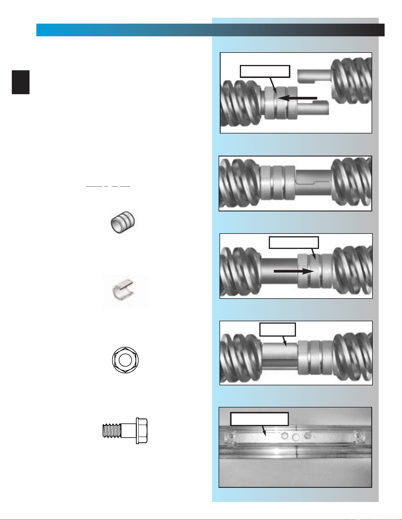
• Slide a collar [11] over exposed end of
screw on “middle” rail as far as it will go.
Fig. 1-8.
• Engage “hook” on “middle” rail with “hook”
on “first” rail section. Fig. 1-9.
• Slide collar toward power head so that it
now covers hooks. Fig. 1-10.
• Snap a clip [12] onto screw behind collar to
hold collar in place. Fig. 1-11.
• Slide middle rail against first rail.
• Place rail clamp [7] on each side of joint
where rails meet. Match up holes in clamps
with holes in rail. (Edge with lip is bottom
of clamp.)
• Secure rail clamps with 4 bolts [8] and 4
nuts [9], hand
tight only. Fig. 1-12.
Fig. 1-8
Fig. 1-9
Fig. 1-10
Fig. 1-11
clip
Fig. 1-12
5/16" Flange nut
5/16" Shoulder bolt w/flange
[
9
]
[
8
]
Collar
Clip
[
11
]
[
12
]
rail clamp
slide collar
slide collar
13
MAIN ASSEMBLY
FOR HELP-1.800.354.3643 OR GENIECOMPANY.COM
NOTE: If installing an extension kit for an
8 feet high door, refer to the instructions
included with the extension kit now.
7. Attach “end” rail section [3C].
• Attach “end” rail in same way as “middle” rail
(step 5). (“End” rail section screw has “hook”
on one end only.)
8. Flip power head/rail assembly over (upside
down), so that entire length of screw is visible
from above.
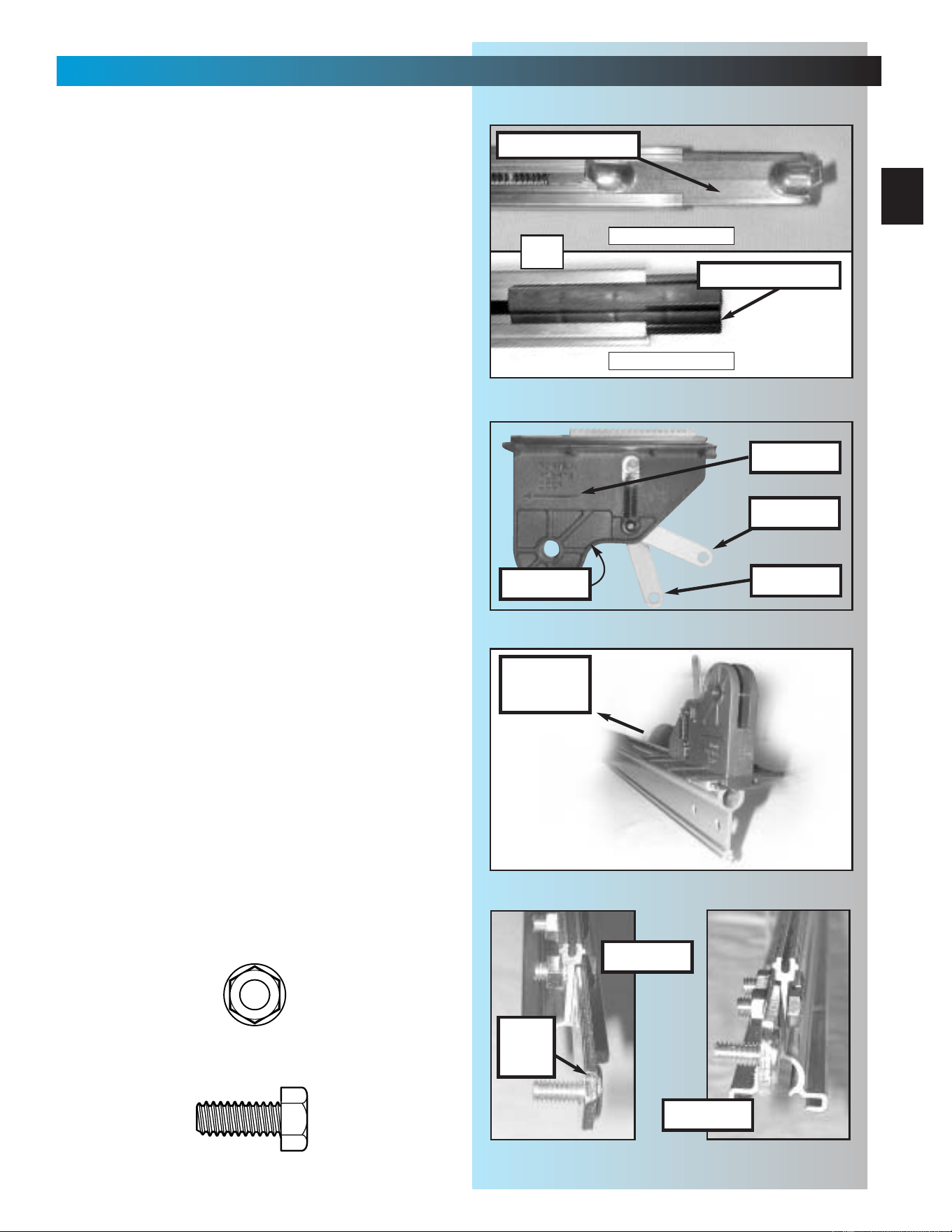
9. Install carriage stop [6].
• With bent tabs facing up, slide carriage stop
into rail. Fig. 1-13.
• Slide carriage stop along rail until it rests
against power head.
10.Install carriage [10].
• Place emergency release lever in released
position. Fig. 1-14.
• Make sure arrow on side of carriage
(Fig. 1-14) is pointing away from power
head. (Emergency release lever will be
facing power head.)
• Slide carriage into rail. Fig. 1-15.
NOTE: Carriage can be used as a temporary
support for the rail while performing the next few
steps of assembly. Slide carriage to mid point of
rail. Place emergency release lever in engaged
position.
11.Flip assembly right side up.
(Rail resting on carriage.)
12. Attach rail strap
[13]
.
• Place rail strap against end of rail so that
attached stud passes in front of end of rail.
Fig. 1-16.
•Line up rail strap holes with rail holes.
• Secure with 2 bolts [46] and 2 nuts [9].
13. Make sure rail assembly is resting straight
and level.
•FULLY TIGHTEN ALL BOLTS AND NUTS IN
RAIL ASSEMBLY.
Fig. 1-13
Fig. 1-14
engaged
released
arrow
Fig. 1-15
power
head
carriage stop
carriage
Fig. 1-16
wrong
correct
rail
strap
5/16" Flange nut
5/16" x 3/4" Hex head bolt
[
9
]
[
46
]
carriage stop
USES BUMPER
NO BUMPER
OR
14
MAIN ASSEMBLY
FOR HELP-1.800.354.3643 OR GENIECOMPANY.COM
14. Attach emergency release knob, cord
and tag.
•Tie an overhand knot in one end of
emergency release cord [17].
–
Slide cord through center of knob
[18]
.
Fig. 1-17.
– Slide cord through hole in emergency
release lever (on carriage).
– Tie a second knot in this end. Fig. 1-18.
– Slip wire of emergency release tag [19]
through hole in emergency release lever
and twist it around itself.
15. Attach limit switches.
•“CLOSE” limit switch
[15B]
.
(Switches are identical.)
– Place “CLOSE” limit switch over top of rail
about 12 inches from r
ail strap. Fig. 1-19.
– Check that white lever is toward
power head.
–Insert set screw [16] into limit switch
hand
tight only to temporarily hold switch
in place. Fig. 1-19A.
– Attach bro
wn wire to switch. Fig. 1-19B.
– Leaving some slack in wire (Fig. 1-20),
run wire down inside groove in top of rail
back to power head.
– Use wire clip [44] to help maintain slack.
Fig. 1-20.
•“OPEN” limit switch
[15A]
.
– Place “OPEN” limit switch over top of rail
about 12 inches from po
wer head. Fig.1-21.
– Check that white lever is on side away from
power head. (This means limit switches
hang off opposite sides of rail. Check this
to help verify they are installed properly.)
–Insert set screw [16] into limit switch hand
tight only to temporarily hold switch in place.
– Attach gre
y wire to switch. Fig. 1-21.
– Leaving some slack in wire (Fig. 1-21),
run wire down inside groove in top of rail
back to power head.
– Use wire clip [44] to help maintain slack.
Fig. 1-21.
• Coil excess wire and tape it to top of power
head. Fig. 1-21A.
Fig. 1-19
A
B
Fig. 1-20
wire clip
pow
er head
Fig. 1-21
A
“close”
switch
“open”
switch
set screw
OPEN GREEN PARTS BAG
Screws for attaching light cover are included in this bag.
Please set aside for use later.
grey wire
brown wire
Fig. 1-17
Fig. 1-18
release
knob
tag
cord
#8-32 x 3/8" Hex head screw
Wire clip
[
16
]
[
44
]
15
SECT 2—INSTALLATION
FOR HELP-1.800.354.3643 OR GENIECOMPANY.COM
NOTE:There are differences in installations
depending on which type of door you have.
These differences are explained throughout
this section. Please note those steps which are
applicable to your particular door.
REFER TO PAGES 2 & 3.
There are two basic types of residential garage
doors. They are:
SECTIONAL DOORS—divided into a set of
narrow panels (usually four) connected by
hinges, so door can “bend” as it rides on a
curved track.
1-PIECE DOORS—consist of one large
panel and swivel on large spring-loaded hinges
on each side of door.
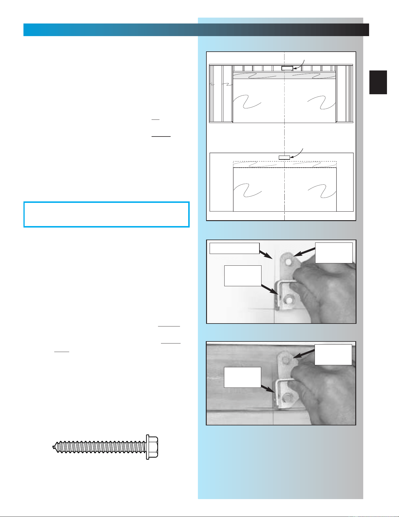
1. Determining header bracket location.
• Find center of door from side to side.
– Measure overall width of door.
(example: 16 feet)
– Divide overall width by 2.
(example: 16
÷
2 = 8 feet)
• Measure this distance from side of door and
draw a pencil line vertically from the top of
the door down approximately 1 foot. This is
the centerline. Fig. 2-1.
– Continue marking centerline on wall
above door from top of door up
approximately 1 foot. Fig. 2-1.
floor
garage door
TYPICAL TRACK GUIDED
CENTERLINE
floor
garage door
TYPICAL TRACKLESS
CENTERLINE
Fig. 2-1
Sectional doors may have one
torsion spring (as shown) or two
springs (one on each side).
Some older doors may have
extension springs.
16
INSTALLATION
FOR HELP-1.800.354.3643 OR GENIECOMPANY.COM
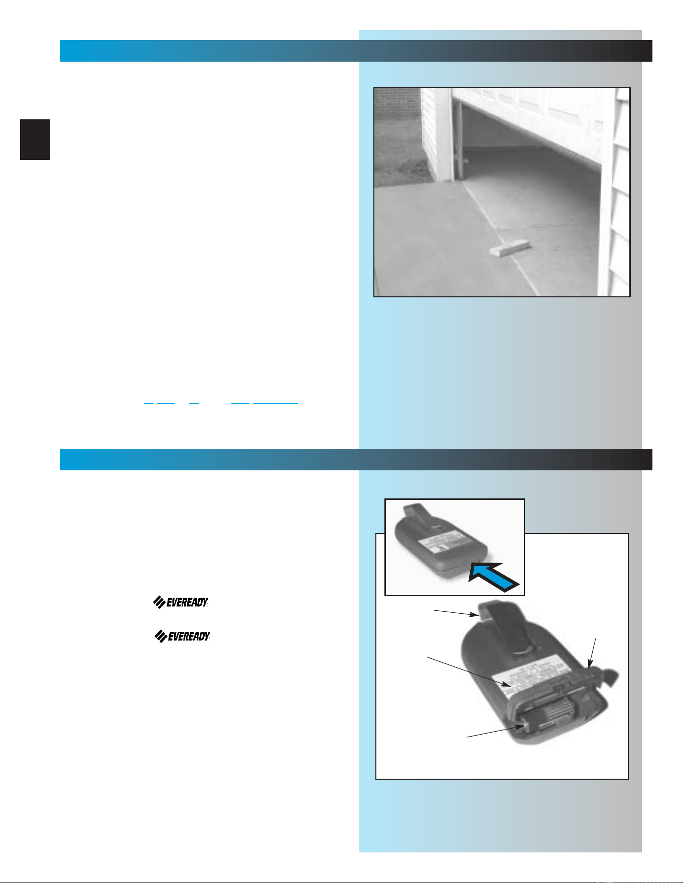
2. Finding highest point of travel.
• While raising garage door manually, watch
top edge of door to see where it reaches its
highest point. This is called “highest point of
travel.” Fig. 2-2.
•A locking pliers can be used to hold the
door in position by clamping it onto the rail.
(A stool, chair, table or any object that can
safely support door will also work.)
–With door held partly open (at its “highest
point”), measure distance from top edge
to the floor.
• Remove support and gently lower door.
• Mark “highest point of travel” at centerline
on wall above door. Fig. 2-3.
NOTE: Following step depends on type of door.
3. Final header bracket mounting location.
•For SECTIONAL DOORS—
add 2-1/2 inches to “highest point of travel”
and mark this height on centerline. Fig. 2-3.
•For ONE-PIECE DOORS—
add 6 inches to “highest point of travel” and
mark this height on centerline. Fig. 2-4.
Highest point of travel.
Measure from here to
floor
SECTIONAL DOORS
ONE-PIECE DOORS
Fig. 2-2
Highest point of travel.
Measure from here to
floor
Fig. 2-3
Highest point of travel.
+6"
Highest point of travel.
+2-1/2"
Fig. 2-4
centerline of door
centerline of door
17
INSTALLATION
FOR HELP-1.800.354.3643 OR GENIECOMPANY.COM
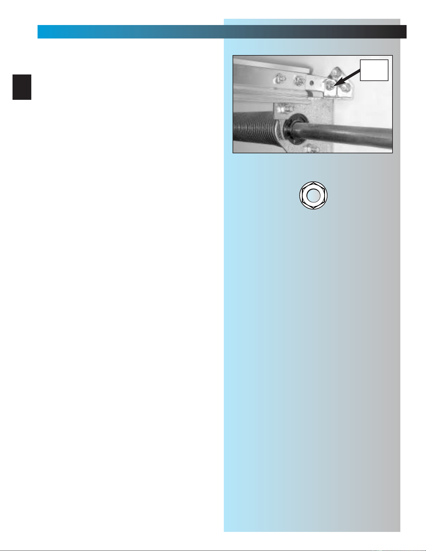
NOTE: If torsion spring interferes with your
final location, mark bracket location 2-1/2" or
6" above torsion spring depending on garage
door type.
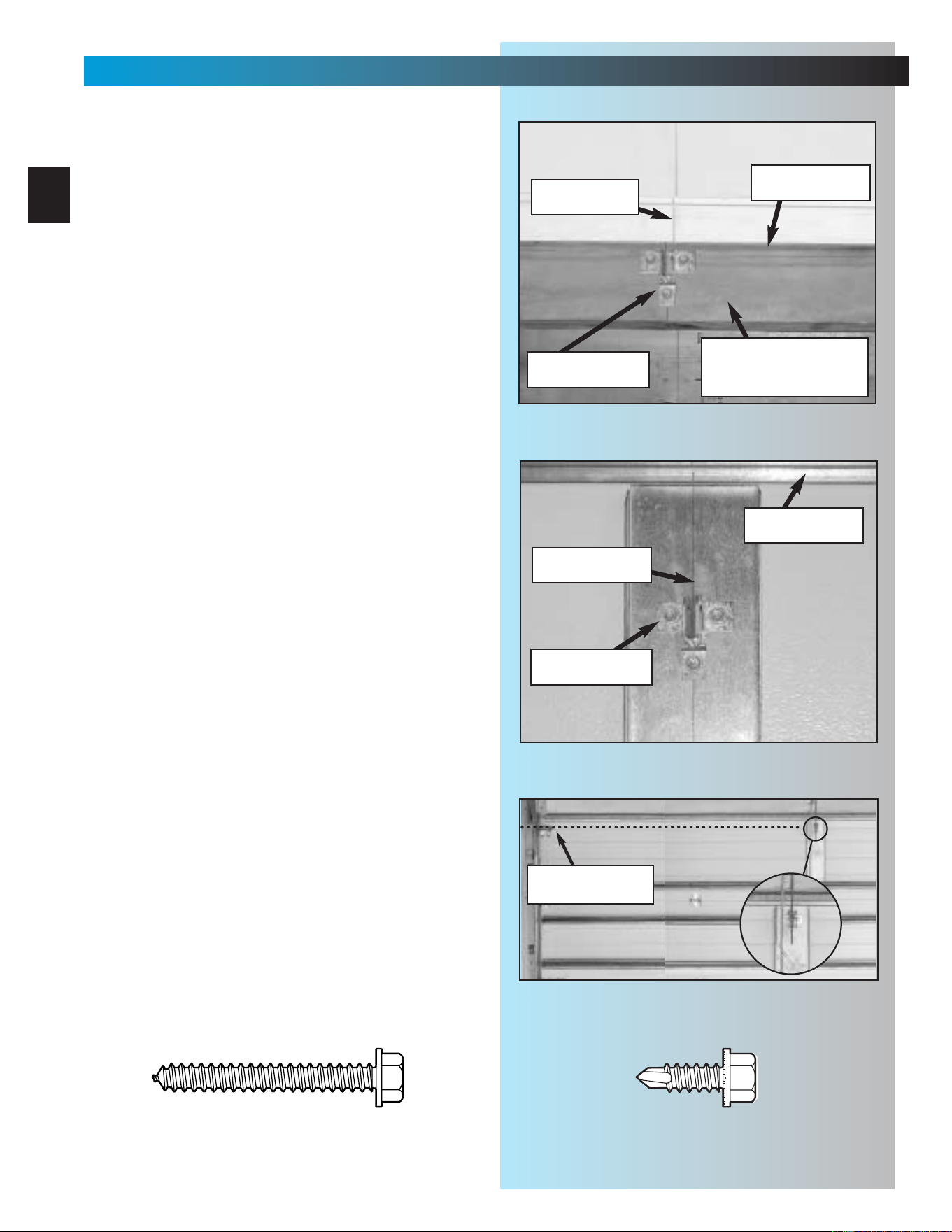
4. Check mounting location for strength.
Header bracket must be attached to
framework of garage. Fig. 2-5.
• If final header bracket position is on
garage
door header, continue with step 5.
• If final header bracket position is abo
ve
garage door header, a mounting plate must
be installed and mounting location must be
remarked before continuing with step 5.
Fig. 2-5.
• If your garage wall is finished (covered with
drywall), continue with step 5.
5. Mounting preparation.
• Hold bracket against wall where final header
bracket height crosses centerline.
• Make sure flange where rail strap attaches,
is on centerline. Fig. 2-6.
• Mark screw hole locations.
– If your wall is finished, take a small “finish
nail” and gently tap it through drywall
where you have marked screw holes to
find out if there is wood behind mounting
location. If your marked location is solid
,
continue with step 6.
– If your marked mounting location is not
solid, a mounting plate must be installed
and mounting location remarked before
continuing. Fig. 2-7 and Fig. 2-5.
6. Mount header bracket [20].
•Drill 5/32 inch pilot holes at marked screw
hole locations.
•Fasten header bracket using 3 lag
screws [22].
floor
ceiling
garage door opening
header
header
studs
wall
C
L
TYPICAL UNFINISHED WALL
floor
ceiling
garage door opening
TYPICAL FINISHED WALL
wooden plate
fastened to wall studs
wooden plate
fastened to wall studs
Fig. 2-5
Fig. 2-7
flange for
rail strap
Fig. 2-6
flange for
rail strap
centerline of door
1/4" x 2" Lag screw
[
22
]
OPEN ORANGE PARTS BAG
header
bracket
header
bracket
18
INSTALLATION
FOR HELP-1.800.354.3643 OR GENIECOMPANY.COM
7. Attaching rail to header bracket.
• Gently set power head on garage floor while
leaning rail strap against header bracket. (It
is recommended that you place a piece of
cardboard or similar material between power
head and floor to prevent scrapes and
scratches to power head.)
NOTE: It may be necessary to support power
head above floor. As little as a few inches, or
as much as 5 or 6 feet depending on position
of torsion spring(s). Be sure to use a stable
support device, such as a ladder.
• Slide threaded stud of rail strap through hole
in flange of header bracket.
•Fasten with nut [9], finger tight only. Fig. 2-8.
Fig. 2-8
5/16" Flange nut
[
9
]
5/16"
FLANGE
NUT
19
INSTALLATION
FOR HELP-1.800.354.3643 OR GENIECOMPANY.COM
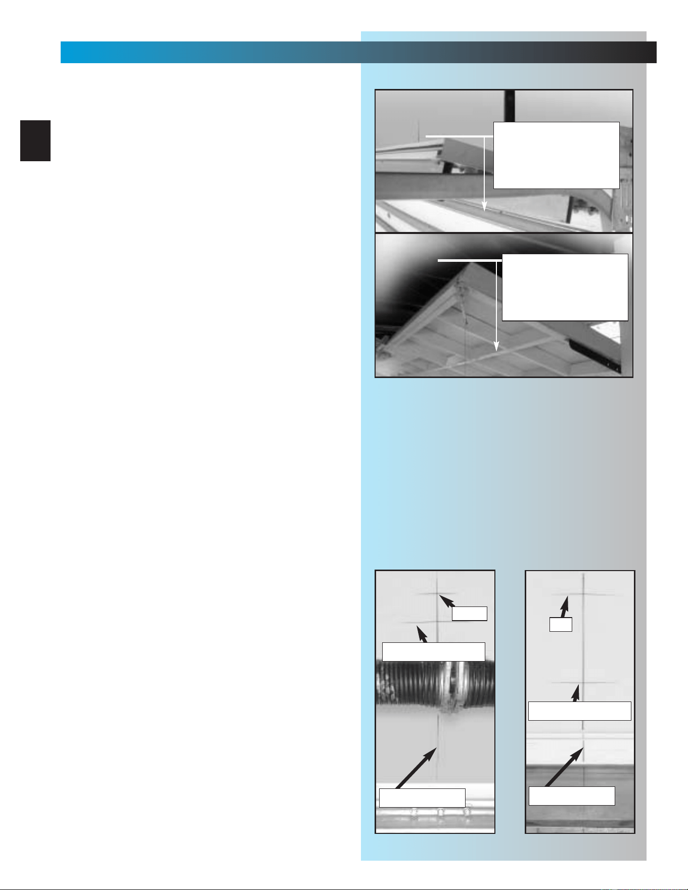
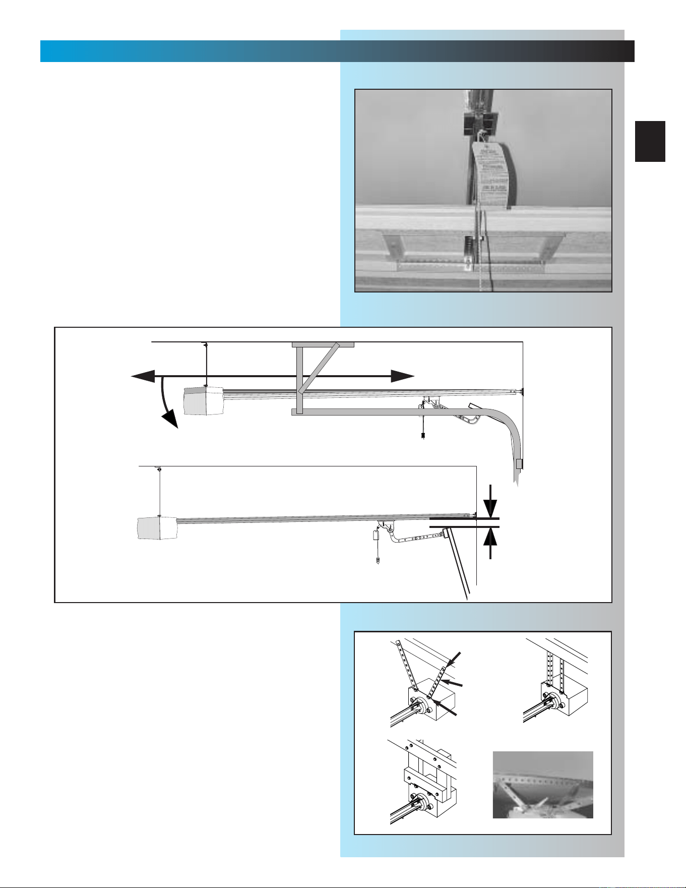
8. Mounting power head.
• Raise power head and support it high
enough that you can manually raise garage
door fully open.
• Line up power head and rail with center of
door. Fig. 2-9.
•Keeping power head centered, mount
to ceiling:
–at proper height;
a. for sectional doors rail should be level
with floor or slightly below level.
Fig. 2-10.
b. for 1-piece doors rail should clear
door by about 2 inches. Fig. 2-10.
– using one of the preferred methods
shown, Fig. 2-11, mount power head.
(It is possible to use other mounting
methods. The critical point to remember is
that the mounting assembly must be
solidly attached and able to support the
weight of the power head.) DO NOT
ATTACH TO DRY WALL OR
SUSPENDED CEILING. It must be
anchored to the framework of the garage.
• Fully tighten rail strap nut.
Fig. 2-9
SECTIONAL LEVEL OR SLIGHTLY BELOW LEVEL
1-PIECE MUST CLEAR DOOR BY 2 INCHES AT HIGHEST POINT OF TRAVEL
2"
Fig. 2-10
Perforated
Angle Iron
Mounting
Straps
FINISHED CEILING
Wood
Fig. 2-11
[22]
[48]
[46]
[9]
20
INSTALLATION
FOR HELP-1.800.354.3643 OR GENIECOMPANY.COM
9. Mounting door bracket [21].
• Center of bracket must be on centerline of
door and must be mounted as high as
possible. Fig. 2-12A & B.
• Hold bracket against door at preferred
location and mark screw holes.
– for wooden doors, drill 5/32 inch
pilot holes.
a. Fasten door bracket using
3 lag screws [22].
b. Check thickness of door against lag
screws. (It may be necessary to
mount door bracket on a 2" x 6",
etc. attached to inside of door to
prevent screws from coming out
other side of garage door.
Fig. 2-12A.
– for light-weight doors
CAUTION: In the case of sectional doors, the
door bracket must not be below the highest set
of rollers. Fig. 2-13.
– there are a wide variety of reinforcements
depending on manufacturer and some are
equipped with hardware that is intended
to be used in place of the door bracket.
Be sure to confirm proper use of
this hardware with your door
manufacturer. Unauthorized improper
use of these attachment systems
could void your warranty.
WHEREVER POSSIBLE—USE DOOR
BRACKET SUPPLIED WITH YOUR
GENIE OPERATOR.
a. Fasten door bracket using
3 self-drilling screws [47].
Fig. 2-12B
Fig. 2-12A
top of door
centerline
centerline
top of door
attached board for
extra thickness
even with or
above top roller
Fig. 2-13
WOODEN ONE-PIECE
LIGHT-WEIGHT SECTIONAL
1/4" x 2" Lag screw
[
22
]
1/4"-20 Self-drilling screw
[
47
]
door bracket
door bracket
1-PIECE DOOR
21
INSTALLATION
FOR HELP-1.800.354.3643 OR GENIECOMPANY.COM
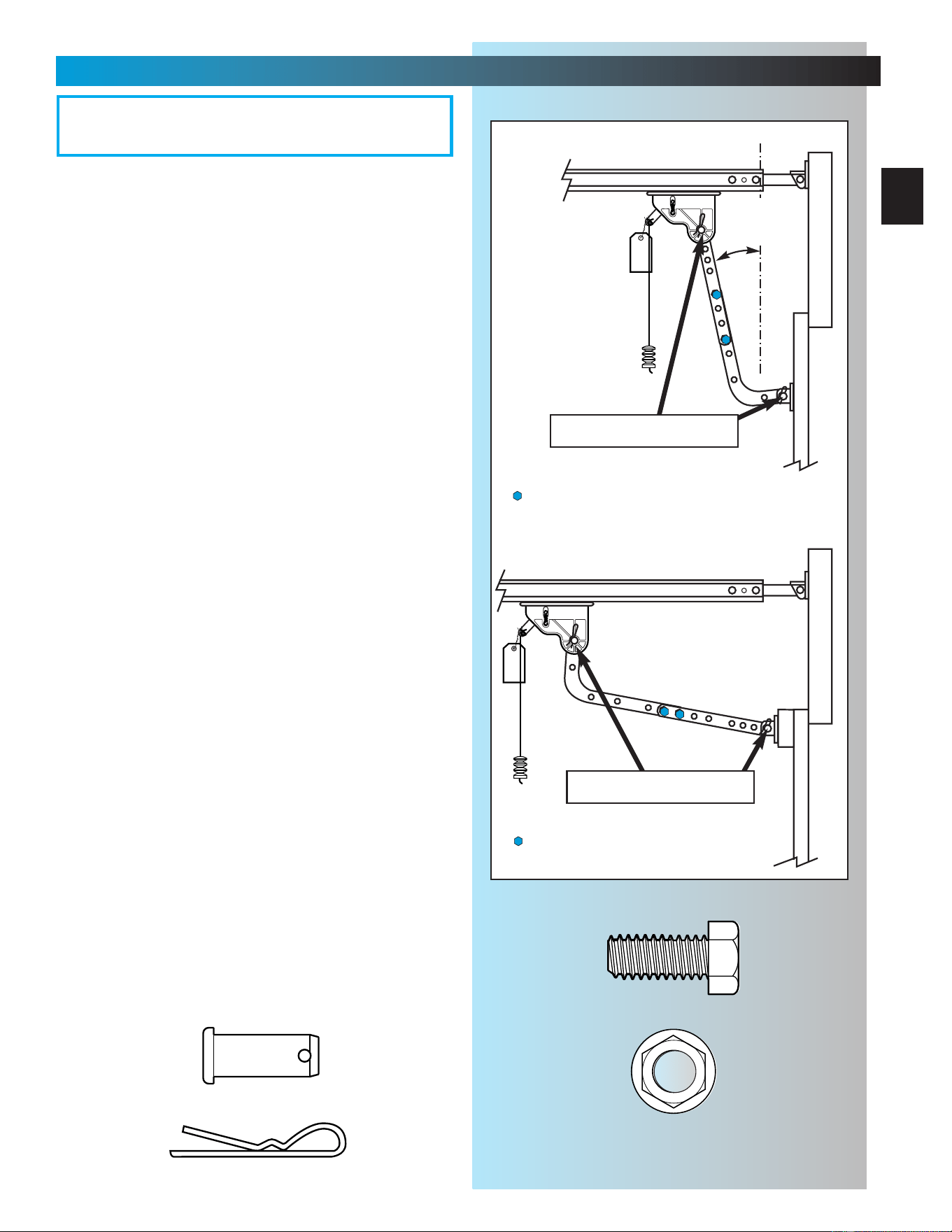
10. Attach door arms [23] and [26].
• For sectional doors.
– Connect short leg of curved arm to
door bracket. Fig. 2-14.
– Use clevis pin [24] and cotter pin [25].
Fig. 2-14.
– Connect straight arm to carriage.
– Use clevis pin [24] and cotter pin [25].
– Overall length of arms together should be
as short as possible, but must not be so
short that they are vertical when the door
is fully closed. Fig. 2-14.
a. Move carriage as necessary to
adjust length.
b. Place bolts [27] and nuts [28] as far
apart as possible. Fig. 2-14.
c. Tighten bolts and nuts.
• For 1-piece doors.
– Connect short leg of curved arm to
carriage. Fig. 2-14.
– Use clevis pin [24] and cotter pin [25].
Fig. 2-14.
– Connect straight arm to door bracket.
– Use clevis pin [24] and cotter pin [25].
–Overall length of arms together should be
as long as possible. Fig. 2-14.
a. Move carriage as necessary to
adjust length.
b. Place bolts [27] and nuts [28] as
close together as possible. Fig. 2-14.
c. Tighten bolts and nuts.
11. Adjust emergency release knob height.
• Knob should hang approximately 6 feet from
the floor.
– adjust as necessary to clear vehicles yet
maintain height where it can be
easily reached.
• Pull cord through lever until knob is at
desired height.
•Tie a new knot at the lever.
• Cut off excess cord.
Fig. 2-14
SECTIONAL DOOR
clevis & cotter pin
clevis & cotter pin
must be
some angle
off vertical.
—bolts/nuts (far apart as possible)
—bolts/nuts (close as possible)
Cotter pin
Clevis pin
3/8" Hex head bolt
3/8" Nut
[
24
]
[
25
]
[
27
]
[
28
]
OPEN YELLOW PARTS BAG
22
SECT 3—SAFE-T-BEAM
®
INSTALLATION
FOR HELP-1.800.354.3643
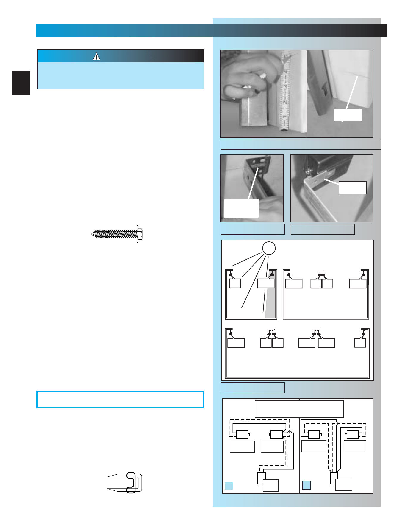
3. Wiring.
• Route wire [29] using either method shown
Fig. 3-5.
• Securely fasten wires to ceiling and walls as
you go using insulated staples [30].
– Staples should be snug only. Staples which
are too tight can cut wires.
NOTE: Operator will not close door automatically
unless the Safe-T-Beam
®
System is installed.
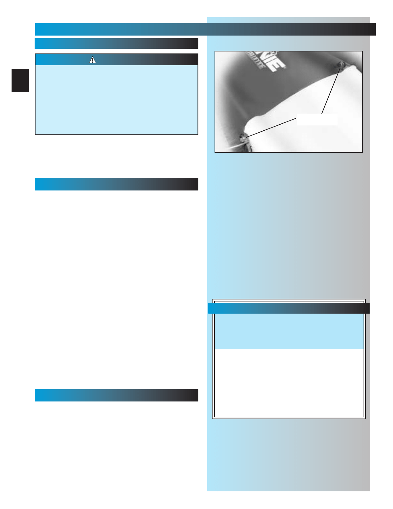
1. Mounting brackets.
• Mark both sides of garage door frame or wall
5" above floor. Fig. 3-1.
• Hold bracket [38] against door frame or wall.
– Check if brackets extend out from wall far
enough, so tongue of bracket is beyond
door, tracks or any door hardware.
– If not:
a. STB bracket extensions are available
at local dealer.
b. Blocks of wood, etc. may be substituted
for extensions.
•Center bracket on your mark Fig. 3-2.
•Fasten each with 2 screws [40]. Fig. 3-2.
(Tongues should point toward each other.)
NOTE: Mounting brackets can be attached to brick
walls or concrete floor using masonry anchors
(not provided).
2. Mounting STB source and sensor.
• If garage has only one garage door.
–Determine which side of garage receives
most direct sunlight Fig. 3-4, and place Red
LED here whenever possible Fig. 3-4.
•For multiple doors.
– Preventing crossed signals is critical.
– Place source and sensor modules on
adjacent doors facing in opposite directions
Fig. 3-4.
NOTE:To help prevent interference from sun,STB sensors
(Green LED) may be placed further from the door opening
where they will spend more time in shadows.
•Slide source/sensor onto tongue of bracket
until it clicks into place Fig. 3-3.
There should be no electrical power to the operator
while installing Safe-T-Beam System
®
wires. If you
have plugged in the power cord–UNPLUG IT NOW.
WARNING
Sensor
Green LED
Source
Red LED
Power
Head
Power
Head
A
B
Dashed Line = striped wire
Solid Line = white wire
tongue
mark
center of
bracket
#10-16 x 1-1/4"
[
40
]
SUN
ONE DOOR
GARAGE
THREE DOOR
GARAGE
RED
LED
RED
LED
GREEN
LED
RED
LED
GREEN
LED
GREEN
LED
GREEN
LED
RED
LED
RED
LED
RED
LED
GREEN
LED
GREEN
LED
TWO DOOR
GARAGE
Fig. 3-1
Fig. 3-5
OPEN RED PARTS BAG
Fig. 3-2
Fig. 3-3
Fig. 3-4
Sensor
Green LED
Source
Red LED
Insulated staple
[
30
]
23
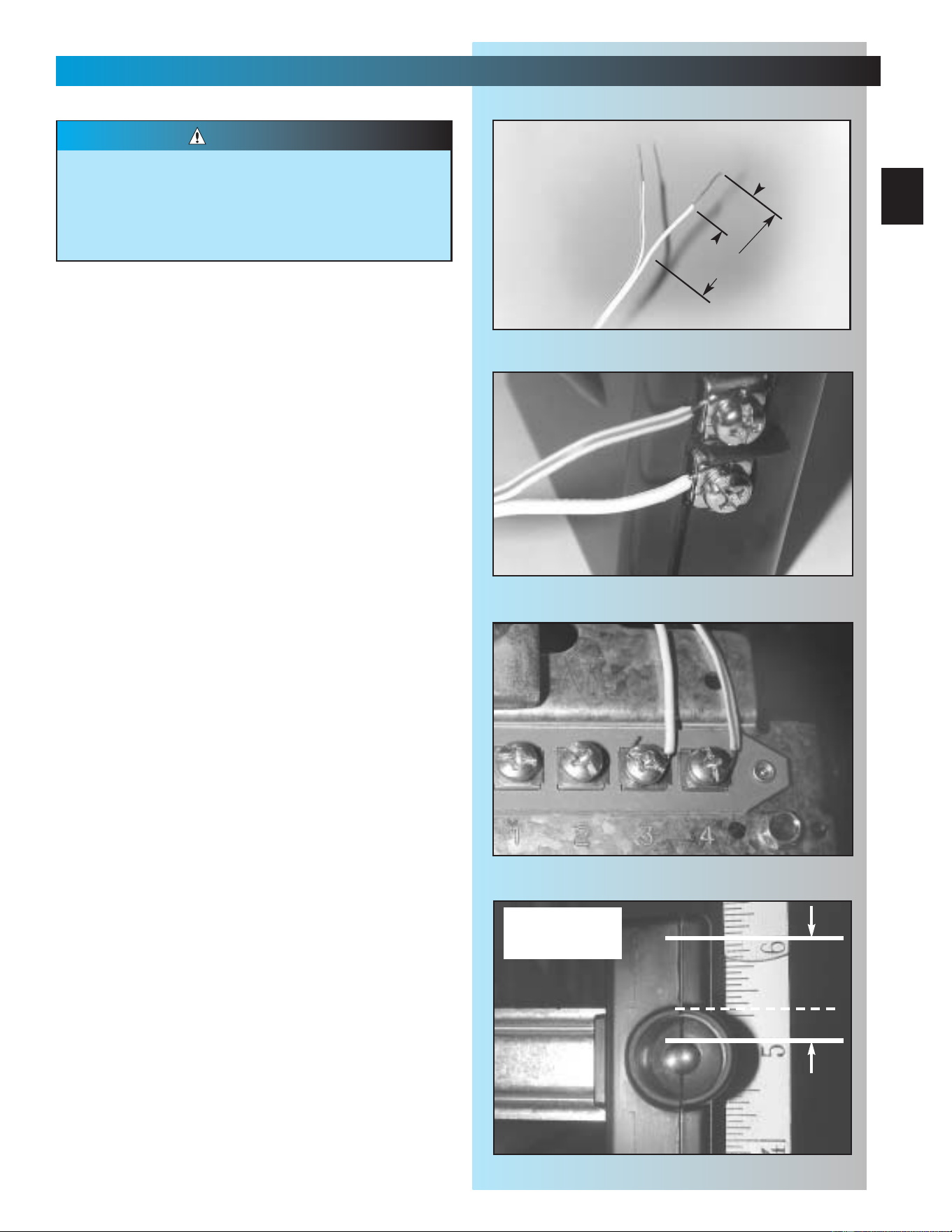
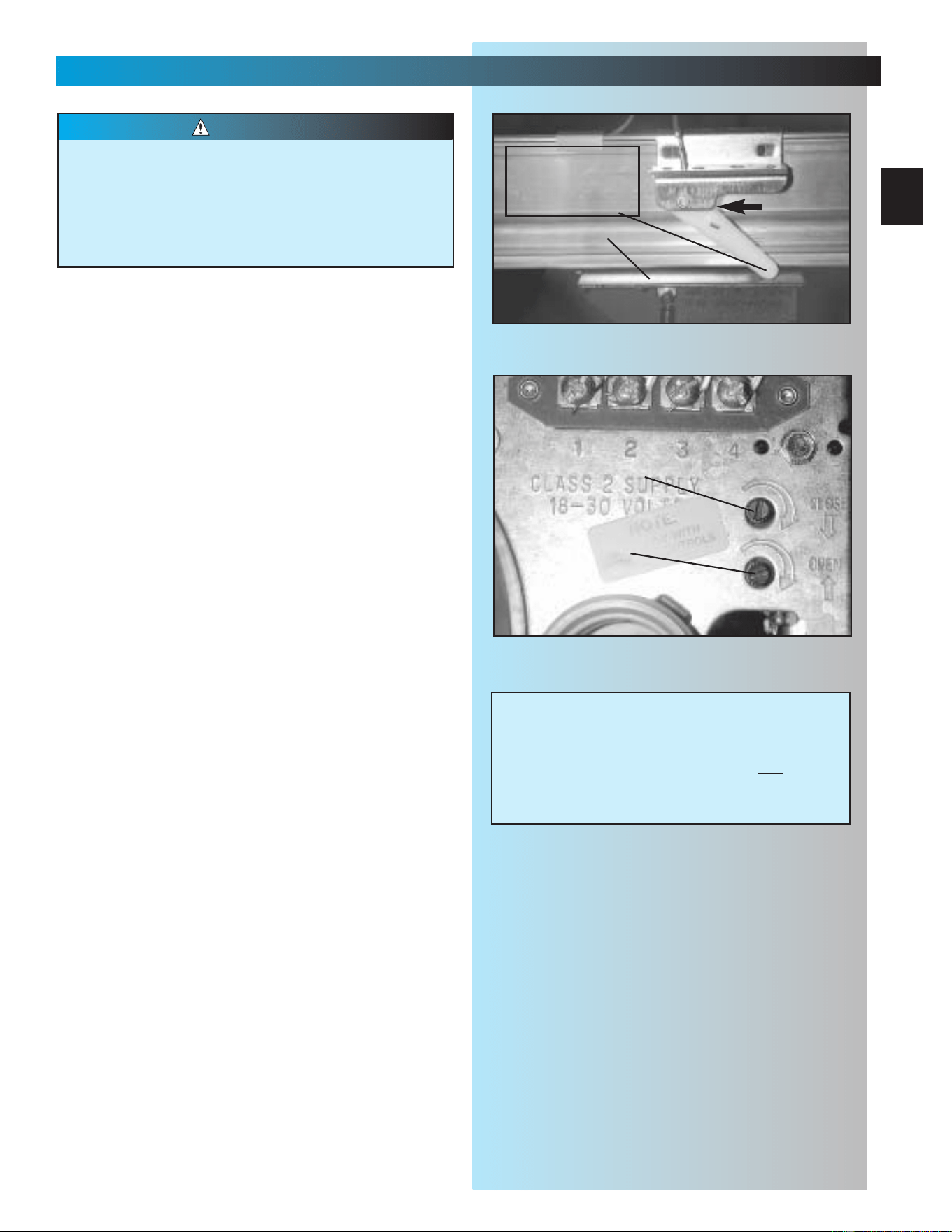
• Make wire attachments at STBs.
– Split and strip wire ends to be connected
as shown Fig. 3-6.
– Loosen terminal screws.
– Insert wire under flat plate and tighten screw.
It does not matter which wire, white or
striped, goes on which terminal Fig. 3-7.
• Make wire attachments at power head.
– STBs are connected to terminals #3 and
#4 on power head Fig. 3-8. It does not
matter which wire, white or striped, goes on
which terminal.
4. Check the following.
• Ensure that no part of door or its hardware is
in path between lenses of source and sensor.
• Ensure that tops of lenses are between 5"-6"
above the floor Fig. 3-9. The brackets are
flexible, and can be adjusted slightly if needed.
NOTE: Safe-T-Beam® alignment check will be
performed following connection to electrical
power (see page 26). DO NOT PLUG IN YET!
(See Illustration on page 3 for a full view of
Safe-T-Beam
®
location.)
Staples which are too tight can cut or pinch
wires. Cut or pinched wires can cause the STB
System to stop working.When using the
insulated staples, make sure you fasten them
only as tightly as needed to hold the wire snugly.
CAUTION
SAFE-T-BEAM
®
INSTALLATION
FOR HELP- GENIECOMPANY.COM
top edge of lens
between 5" - 6"
above floor.
Fig. 3-6
≈1-1/4" to 1-1/2"
≈1/2"
Fig. 3-7
Fig. 3-8
Fig. 3-9
24
SECT 4—WALL CONTROL INSTALLATION
FOR HELP- 1.800.354.3643
Fig. 4-1
1. Run wire from power head to wall control
• Find location for wall control:
–In sight of door and away from moving parts.
– At least 5 feet from floor, so small
children cannot reach it.
• Route wire from wall control to power head.
• Use staples to fasten wire to ceiling and wall.
NOTE: Use only staples included
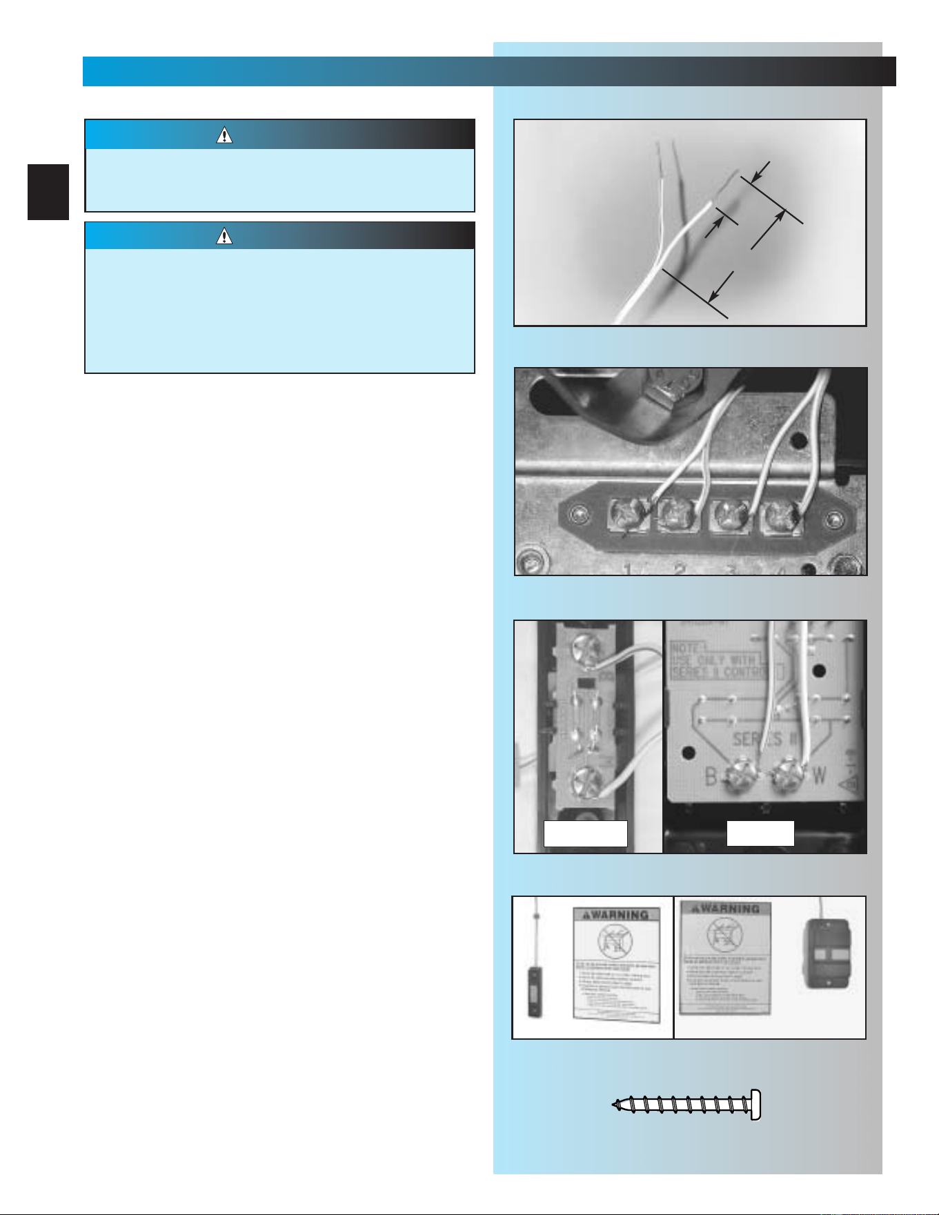
2. Split wires at ends and remove 1/2 inch of
insulation from end of each Wire. Fig. 4-1.
3. Attach wires to terminals. Fig. 4-2, Fig. 4-3.
• Loosen (Do Not Remove) screws from
Terminals at power head and wall control
• Connect wires to power head
– White wire to terminal
#
1
–Striped wire to terminal
#
2
– Tighten screws
• Connect wires to wall control
– Striped wire to terminal “B”
– White wire to terminal “W”
– Tighten screws
4. Mount wall control. Fig. 4-4.
•For Wall Console or Wall Button.
– Use pan head screws [34].
5. Mount entrapment warning label. Fig. 4-4.
• Remove protective backing.
• Stick label to wall next to wall control.
–Tacks or staples may be required on some
rough texture surfaces.
NOTE: Additional wall controls are available from
your dealer. ONLY ONE OF YOUR WALL CONTROLS
MAY BE THE LIGHTED TYPE. If you have a lighted
wall control, all your additional controls must be
un-lighted. More than one lighted wall control per
operator will cause a malfunction.
Power must be removed before attaching wires.
Be sure ends do not touch each other or other
terminals.
WARNING
•Use of any other wall control can cause the
door to operate unexpectedly and the light
not to work.
•Cut or pinched wires can cause door
operator to malfunction. Drive staples just
tight enough to hold wire.
CAUTION
1/2"
1-1/4” to 1-1/2"
Fig. 4-2
button
console
Fig. 4-3
Fig. 4-4
#6 x 1-1/4" Pan head screw
[
34
]
25
WALL CONTROL OPERATIONAL FEATURES
FOR HELP- GENIECOMPANY.COM
Fig. 4-5
1. Wall console. Fig. 4-5.
A. Vacation locking switch.
– Lock disable all controls after door closes..
– Unlock allows all controls to work normally.
NOTE: Carriage must stay in contact with
“CLOSE” limit switch in order for the vacation
locking switch to work.
B. Door control button.
– Opens and closes door from inside garage.
– Lights on shows system has power available
and vacation switch is not locked.
–Lights out shows either power is not
available or vacation locking switch is locked.
C. Independent light control.
–Turns operator lights on and off without
moving door.
2. Wall Button
– Operates door from inside garage.
A
B
C
SECT 5—LIGHT & LENS INSTALLATION
FOR HELP-1.800.354.3643
1. Install light bulbs.
•2bulbs.
– No more than 60 watts each.
– Do Not use short neck bulbs.
–Whenever possible, use bulbs rated for:
Rough service
Vibration
Appliances
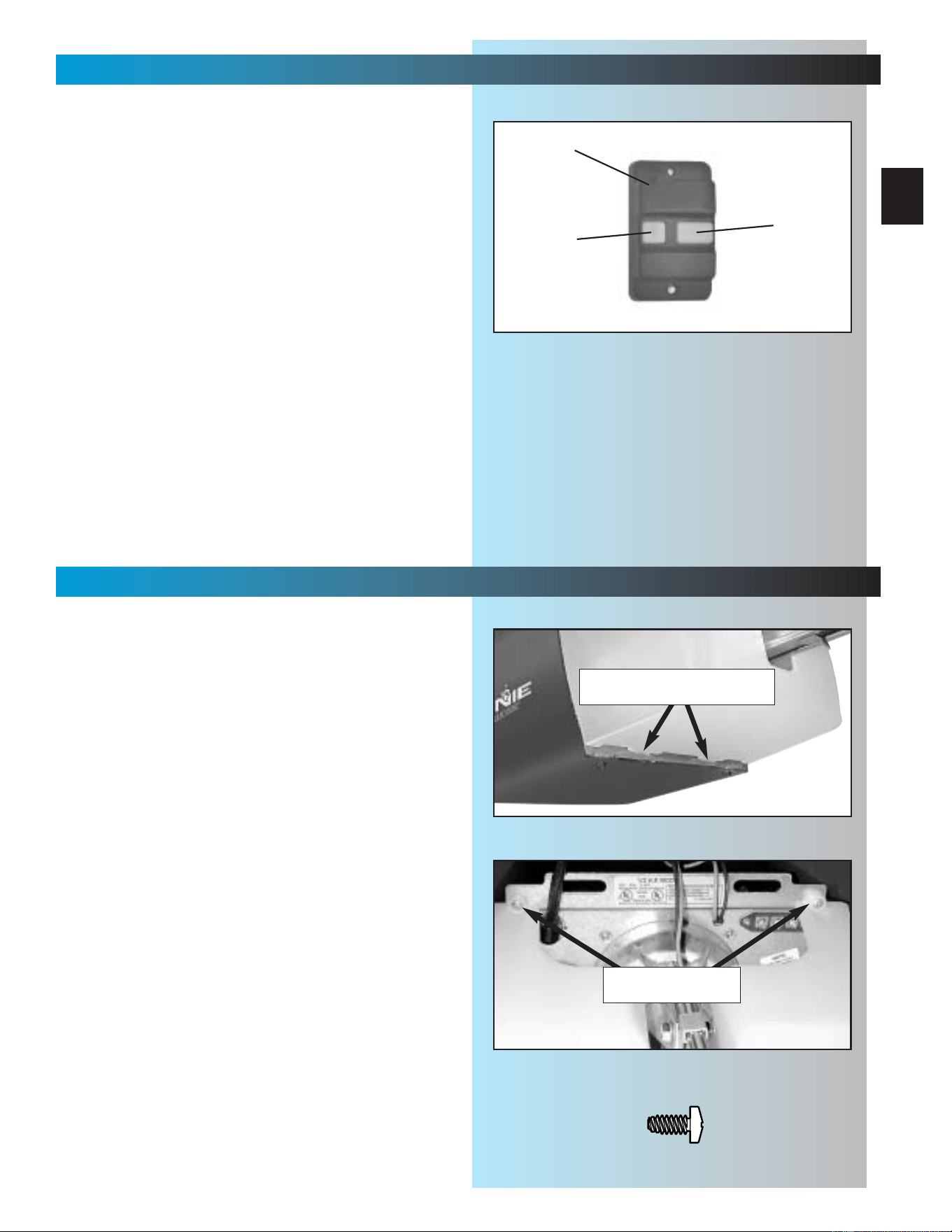
2. Install lens.
• Hook bottom hinges into slots at bottom of
front plate. Fig. 5-1.
• Swing lens up over lights. Check for alignment
between the screw holes in the Lens and those
on the metal front plate.
• Lens will be fastened with 2 pan head screws.
([42] green parts bag). Fig. 5-2.
DO NOT FASTEN YET! Wait until you have
completed programming the Remote Controls.
Fig. 5-1
Fig. 5-2
#8 x 3/8" Pan head screw
[
42
]
bottom of lens cover hooks
into slots in front plate
pan head screws
secure top of lens
26
SECT 6—CONNECTING POWER
FOR HELP-1.800.354.3643 OR GENIECOMPANY.COM
Fig. 6-1
To reduce the risk of electrical shock, this
equipment has a grounded type plug that
includes a third (grounding) pin.This plug will
only fit a grounded type outlet. If you do not
have a grounded outlet, contact a qualified
electrician to install one. DO NOT alter the plug
in any way. The door operator must be properly
grounded in order to prevent personal injury
and damage to the components.
WARNING
WITH GROUNDED PLUG:
1. Check local building codes.
• Does building code require permanent wiring?
– If not, skip to step 9.
– If yes, have an electrician perform steps 2
through 8.
Instructions for electrician.
2. Remove power from circuit.
3. Remove motor cover (Fig. 6-1).
• Remove 4 screws [41] from cover and slide off
back of power head.
4. Remove and discard power cord.
• Cut off power cord inside power head.
NOTE:There must be at least 6 inches of black
and white wire inside the power head (Between
splice and entrance bushing).
• Remove and throw away power cord, strain
relief and knock-out.
5. Install suitable entrance bushing.
6. Connect permanent wiring to power head wires.
• Connect white supply line to white wire.
• Connect black supply line to black wire.
• Connect ground to green wire (ground).
NOTE: Use only U.L. recognized wire nuts
7. Replace motor cover.
•Slide motor cover back on.
• Replace and tighten 4 screws.
8. Reconnect power to circuit.
9. Plug in door operator.
• See warning above.
• Plug door operator into a grounded outlet.
•Perform STB
®
alignment check (Fig. 6-2).
CONNECT POWER WITH PERMANENT WIRING
CONNECT POWER WITH PLUG
screws
Safe-T-Beam
®
Alignment Check
After turning the electrical power on, if the
STBs are not in proper alignment, the red
LED (Source) will blink continuously.
To correct the problem – the brackets are
flexible and can be adjusted slightly to bring
the system into alignment.
When the STBs are in alignment the red LED
will stop blinking and stay on.
Fig. 6-2
27
SECT 7—SETTINGS
(FORCE & LIMITS) FOR HELP-1.800.354.3643 OR GENIECOMPANY.COM
Fig. 7-1
1. Set limit switch position.
• Check door fully closed.
– If not, close door manually.
• Check carriage is between limit switches.
–
If not, move “CLOSE” limit switch (brown wire)
to new position between door and carriage.
– Slide “CLOSE” limit switch back toward
carriage until lever is fully lifted. Fig. 7-1.
–Tighten limit switch set screw.
• Manually open door to fully open position..
• Check carriage is between limit switches.
– If not, move “OPEN” limit switch to new
position between power head and carriage.
– Slide “OPEN” limit switch back toward
carriage until lever is fully lifted. Fig. 7-1.
–Tighten limit switch set screw.
2. Adjust opening force.
• Engage Carriage by pulling Emergency
Release Lever toward Powerhead until
Lever snaps into engaged position.
• On front panel of power head—find adjusting
screw marked “CLOSE.” Fig. 7-2.
•
Turn screw gently counterclockwise until it stops.
NOTE:
Little force required to move adjusting screws.
• Run operator using wall control.
•Observe door runs to “CLOSE” limit switch.
– If not, increase closing force by turning
“CLOSE” adjusting screw clockwise slightly
(about 1/16 turn).
• Repeat until door runs to “CLOSE” limit switch.
• Check door is fully closed.
– If not, move “CLOSE” limit switch toward
door as necessary to achieve fully closed.
3. Adjust closing force.
• On front panel of power head—find adjusting
screw marked “OPEN.” Fig. 7-2.
•
Turn screw gently counterclockwise until it stops.
• Run operator using wall control.
•Observe door runs to “OPEN” limit switch.
– If not, increase opening force by turning
“OPEN” adjusting screw clockwise slightly
(about 1/16 turn).
• Repeat until door runs to “OPEN” limit switch.
• Check door is fully open.
–
If not, move “OPEN” limit switch toward power
head as necessary to achieve fully open.
Door opens rapidly
•Keep clear of door and its path.
•Keep ladder to side of power head to
prevent being hit by moving parts.
Be sure and set force adjustments at minimum
required to operate door.
CAUTION
Fig. 7-2
CLOSE
OPEN
CARRIAGE
SLIDE
SWITCH
lever
(actuator arm)
fully lifted
NOTE:
When the garage door is closing and
contacts a vehicle or other obstruction, the
contact reverse mechanism may not
prevent damage to the obstruction, garage
door or garage door operator.
28
SETTINGS
(CONTACT REVERSE) FOR HELP-1.800.354.3643 OR GENIECOMPANY.COM
Fig. 7-3
Limit switch adjustments must be completed
before running contact reverse test.
1. Test contact reverse.
• Open door using wall control.
•Lay 2" x 4" board
*
on floor in center of garage
door opening. Fig. 7-3.
•Close door using wall control.
– Door should stop and reverse
within 2 seconds of contacting the board.
– If door does not reverse properly:
a. Decrease closing force a small amount
by turning the “CLOSE” force adjustment
screw slightly counterclockwise.
b. Test contact reverse again.
c. Repeat steps a. and b. until contact
reverse works properly.
*If you don’t have a 2" x 4" board handy, any object
1-1/2 inches high that can withstand being hit by the
garage door without sustaining damage is fine.
NOTE: If door is
stopping but not reversing,
“CLOSE” limit switch must be moved closer to
door.
SECT 8—BATTERY & VISOR CLIP
FOR HELP-1.800.354.3643 OR GENIECOMPANY.COM
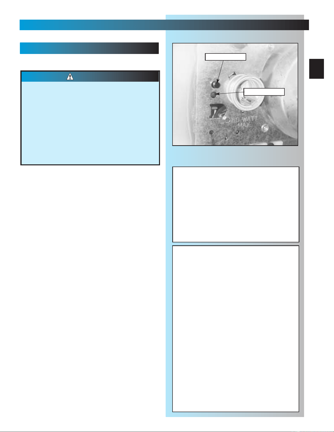
Visor Clip
Battery
Battery
Cover
1. Install/replace battery Fig. 8-1.
• Using a pen or similar object, gently push in
on tab.
•Cover snaps open. Remove old battery.
•Observe polarity markings (+,-) inside
battery compartment.
• Match new battery to polarity markings and
instal new A23, 12 Volt battery.
• Replace battery cover.
NOTE: Use only A23, 12 Volt battery.
2. Attach visor clip Fig. 6-1.
• Slide clip in slot on back of remote control.
– Snap in place.
Model
Number
Fig. 8-1
29
SECT 9—PROGRAMMING REMOTE CONTROLS
FOR HELP-GENIECOMPANY.COM
Fig. 9-1
Moving door can cause serious injury or death.
• Keep people clear of opening while door
is moving.
• Do not allow children to play with
remote controls.
If Safety reverse does not work properly:
• Close door and disconnect operator using
emergency release.
• Do not use door operator, remote controls,
or wireless keypad.
• Refer to door and door operator owner’s
manuals before attempting any repairs.
WARNING
PROGRAMMING REMOTE CONTROLS
NOTE: Remote controls will not close door if
Safe-T-Beam® malfunctions.
NOTE: When programming remote control, it must
be at least 24 inches from the antenna.
1. Program one button remote.
• Lower lens cover.
• Locate learn code button and learn indicator on
power head Fig. 9-1.
•
Press and release learncode button.
–
Red learn indicator blinks 2 times per second.
•
Press remote control button once within
30 seconds.
– Red learn indicator stays lit.
• Press remote control button again.
– Red indicator goes out and memory
is stored.
NOTE: If red indicator blinks approximately 4
times per second, programming has stopped.
If programming stops, repeat above steps.
2. Program multi-button remote.
• Repeat step 1 above “Program one-button
remote” for each button and operator.
NOTE: Each button on a multi-button remote
control is for a different operator.You cannot use
more than one button on a multi-button remote for
a single door.
3. Operating remote.
• Press button once:
– If door is at up or down limit, door will move
away from that limit.
–If door is stopped between limits, it will move
toward the limit where it was last stopped.
– If door is moving, it will stop.
NOTE: Door automatically stops at end of open or
close cycle.
NOTE: Each remote device must be
programmed separately
Learn Button
Learn Indicator
To erase all receiver memory, such as
following loss of remote, home sale or
tenant turn-over.
• Press and hold learn code button for
10 seconds or until learn code
indicator goes out—memory is erased.
• Program remotes as before.
FCC and IC CERTIFIED
This device complies with FCC Part 15 and RSS
210 of Industry Canada. This equipment has been
tested and found to comply with the limits for a
Class B digital device, pursuant to Part 15 of the
FCC Rules. These limits are designed to provide
reasonable protection against harmful interference
in a residential installation. This equipment
generates, uses and can radiate radio frequency
energy and, if not installed and used in accordance
with the instructions, may cause harmful
interference to radio communications. However,
there is no guarantee that interference will not
occur in a particular installation. If this equipment
does cause harmful interference to radio or
television reception, which can be determined by
turning the equipment off and on, the user is
encouraged to try to correct the interference by one
or more of the following measures:
• Re-orient or relocate the receiver antenna.
• Increase the separation between the operator
and receiver.
• Connect the operator into an outlet on a circuit
different from that to which the appliance
is connected.
• Consult the dealer.
IMPORTANT
SAFETY
INSTRUCTIONS
30
WARNING
To reduce the risk of
severe injury or death:
TRANSMITTER
COMPLIANCE
STATEMENT
Transmitters comply with all United States and Canadian legal
requirements as of the date of manufacture. No warranty is
made that they comply with all legal requirements of any other
jurisdiction. If transmitters are to be used in another country,
the importer must determine compliance with any local laws
and regulations which may differ from United States and
Canadian requirements prior to use.
Los transmisores cumplen con todas las reglamentaciones
legales de los Estados Unidos y del Canad , en la fecha de
fabricaci n. Ninguna garant a se da que cumplan con todas las
reglamentaciones legales de ninguna otra jurisdicci n. Si los
transmisores se van a utilizar en otro pa s, el importador debe
determinar si cumplen con las reglamentaciones y leyes
locales que puedan ser diferentes a las reglamentaciones
de los Estados Unidos y del Canad , antes de usar los mismos
.
Sendeger te entsprechen allen gesetzlichen Bestimmungen in
den USA und Kanada zum Zeitpunkt der Herstellung. Wir
bernehmen keine Gew hrleistung f r die Einhaltung aller
gesetzlichen Bestimmungen in anderen L ndern. Sollen
Sendeger te in anderen L ndern eingesetzt werden, so muss
der Importeur vor dem Gebrauch sicherstellen, dass die
Sendeger te auch solchen lokalen Bestimmungen entsprechen,
welche von den Bestimmungen der USA und
Kanadas abweichen
.
Les metteurs sont conformes la r glementation am ricaine
et canadienne compter de leur date de fabrication. Aucune
garantie n est stipul e indiquant qu ils sont conformes toutes
les prescriptions juridiques d autres autorit s. Si les metteurs
sont utilis s dans d autres pays, il incombe l importateur d en
d terminer leur conformit aux lois et r gles locales pouvant
diff rer de celles des tats-Unis et du Canada avant toute
utilisation desdits metteurs.
1 READ AND FOLLOW ALL
INSTRUCTIONS.
2Never let children operate or play with the
Door Controls. Keep the Remote Control
away from children.
3Always keep the moving door in sight and
away from people and objects until the
door is completely closed. NO ONE
SHOULD CROSS THE PATH OF THE
MOVING DOOR.
4 NEVER GO UNDER A STOPPED,
PARTIALLY OPEN DOOR.
5Test Opener monthly. The door MUST
reverse on contact with a 1-1/2" high
object (or a 2" x 4" board laid flat) at the
center of the doorway on the floor. After
adjusting either the Force or the Limit of
travel, retest the Door Opener. Failure to
adjust the Opener properly may cause
severe injury or death.
6When possible use the Emergency
Release only when the door is closed.
Use caution when using this Release with
the door open. Weak or broken springs
are capable of increasing the rate of door
closure and increasing the risk of severe
injury or death.
7 KEEP GARAGE DOORS PROPERLY
BALANCED. See Owner's Manual. An
improperly balanced door increases the
risk of severe injury or death. Have a
Genie Factory Authorized Dealer make
repairs to cables, spring assemblies, and
other hardware.
8
SAVE THESE INSTRUCTIONS.
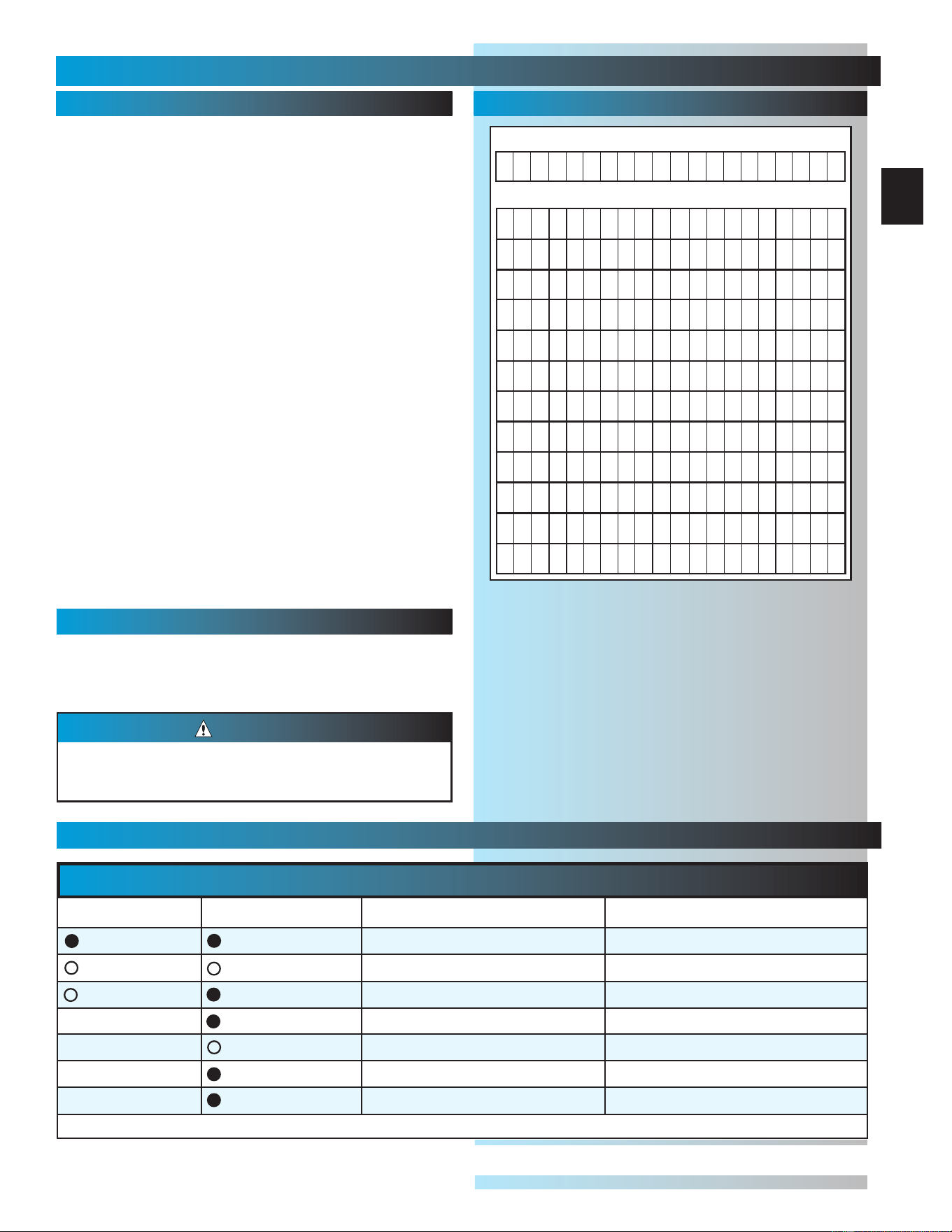
YEAR
1234567891011 12 13 14 15 16 17 18 19 20
MONTH
JJJJJJJJJJJ JJJJJJJJJ
FFFFFFFFFFF FFFFFFFFF
MMMMMMMMMMM MMMMMMMMM
AAAAAAAAAAA AAAAAAAAA
MMMMMMMMMMM MMMMMMMMM
JJJJJJJJJJJ JJJJJJJJJ
JJJJJJJJJJJ JJJJJJJJJ
AAAAAAAAAAA AAAAAAAAA
SSSSSSSSSSS SSSSSSSSS
OOOOOOOOOOO OOOOOOOOO
NNNNNNNNNNN NNNNNNNNN
DDDDDDDDDDD DDDDDDDDD
STB
SELF-DIAGNOSTIC TROUBLESHOOTING
ON
ON
NORMAL OPERATION
NONE REQUIRED
OFF
OFF
1.POWER HEAD NOT POWERED
2.WIRING FROM POWER HEAD BAD
1.CHECK BREAKERS, FUSES, PLUGS
2.CHECK WIRING FOR OBVIOUS SHORTS
OFF
ON
1.WIRING TO SOURCE MISSING OR BAD
2.POWER HAS BEEN INTERRUPTED
1.CHECK WIRING
2.REMOVE POWER AND REAPPLY
2 BLINKS, PAUSE (REPEAT)
ON
1.BEAM NOT ALIGNED 2. BEAM OBSTRUCTED
3.SENSOR DEFECTIVE
1.CHECK ALIGNMENT 2. CHECK FOR OBSTRUCTION
3.CALL CUSTOMER SERVICE
1.WIRE TO SENSOR MISSING OR BAD
2.SENSOR DEFECTIVE
1.CHECK WIRING
2.CALL CUSTOMER SERVICE
OFF
ON
1.SENSOR RECEIVING INTERFERENCE
1.
ATTEMPT TO DETERMINE SOURCE OF INTERFERENCE
2.CALL CUSTOMER SERVICE
ON
1.SOURCE NOT SENDING PULSES
2.SOURCE DEFECTIVE
1.CALL CUSTOMER SERVICE
2.CALL CUSTOMER SERVICE
NOTE:IF OPERATING PROBLEM EXISTS, THE DOOR CAN BE CLOSED IF YOU: 1.DISCONNECT THE STB SYSTEM FROM THE OPERATOR AND 2.HOLD WALL CONTROL BUTTON
DOWN UNTIL DOOR IS CLOSED.
(
REMOTE CONTROL & WIRELESS KEYPAD WILL NOT WORK WITHOUT STB
)
SOURCE
(
RED LED
)
SENSOR
(
GREEN LED
)
INDICATED CONDITION
REQUIRED ACTION
2 BLINKS, PAUSE (REPEAT)
3 BLINKS, PAUSE (REPEAT)
4 BLINKS, PAUSE (REPEAT)
CUSTOMER SERVICE: 1.800.354.3643 or www.geniecompany.com
TROUBLESHOOTING
FOR HELP-1.800.354.3643 OR GENIECOMPANY.COM
Door springs and hardware.
•Oil door rollers, bearings, and hinges.
– Use silicone lubricant or light oil.
NOTE: Do not operate door automatically or manually if
springs are broken. CONTACT A PROFESSIONAL FOR
SERVICE.
Balance door.
• Close door.
• Release carriage from rail assembly.
– Pull emergency release knob down.
• Raise door manually about 3 feet.
– Door should stay in that position.
NOTE: If door moves, HAVE DOOR SERVICED BY
A PROFESSIONAL.
• Reattach carriage to rail assembly.
– Pull emergency release knob toward power head.
• Close door
Contact reverse.
•Lay 2” x 4” board flat on the floor in the center of
garage doorway (See page 28).
• Close door using wall button or remote control.
NOTE: If door fails to reverse on contact with board. See
page 28, CONTACT REVERSE. If operator still fails,
replace operator or HAVE THE OPERATOR SERVICED BY
A PROFESSIONAL.
MONTHLY MAINTENANCE
Drive Screw
• Lubricate drive screw.
– Use GENIE GLU3 lubricant.
Use only GENIE GLU3 lubricant, because other
lubricants may damage operator.
CAUTION
YEARLY MAINTENANCE
SECT 10—MAINTENANCE & TROUBLESHOOTING
MAINTENANCE CHECK-OFF
31
Just mark the appropriate box each time you
perform routine maintenance.
One less thing you will have to try and
remember on your busy schedule is whether
or not you did the maintenance last month.
32
MAINTENANCE & TROUBLESHOOTING
CAUTION
Door starts for no reason. Check staples on wire from power head to wall control. If they cut into insulation, they can short wires.
If wire is cut, replace it.
Was a remote control lost or stolen? Erase all remote control codes from receiver memory and reprogram.
Wall control button sticking. Check operation of buttons.
Door starts down, then
stops before it’s closed.
Check CLOSE limit switch setting (See Section 7)
Check for shorted wires
Door starts down, then
stops and goes back up.
Check force adjustment (See Section 7).
Check CONTACT REVERSE (See Section 7).
Check for light beam obstruction or misalignment of Safe-T-Beam
®
(See Section 3).
Check STB self-diagnostic code.
Door will only run closed. Check OPEN limit switch for short and proper wiring.
Check force adjustment (See section 7).
Check for broken door spring.
Door will only run open.
Check Safe-T-Beam
® System (See section 3).
Check CLOSE limit switch for short and proper wiring.
Check force adjustment (See Section 7).
Remote control has
less than 25 feet
operating range.
Relocate remote control inside car.
Point remote control at door.
Replace battery.
Do Not attempt to retune remote controls.
Door starts up, but
stops before it’s
completely open.
Be sure door is in good repair, properly lubricated and balanced.
Check OPEN limit switch setting (See section 7).
Check force adjustment (See section7).
Check for broken door spring.
Operator runs, but door
does not move.
Make sure carriage is engaged.
Check force adjustment (See Section 7).
Operator works from wall
control, but not from
remote control.
Program remote control code into receiver memory (See section 9).
If one remote control works and another does not, check battery, remote control type (Series II ) and
frequency of non-working unit (See section 9).
Noisy operation. Be sure all fasteners are tight.
Be sure door is in good repair, properly lubricated and balanced (See Monthly Maintenance section).
STB System malfunction. Use self-diagnostic STB System troubleshooting information to maintain safe operation
(See section 3).
Use this guide to correct problems with your door
operator. If these solutions do not work, call
Customer Service.
Use only with included SERIES II wall control
Use of any other wall control can cause the door
to operate unexpectedly and the light not to work.
PROBLEM SOLUTIONS
Operator does not run
from wall control.
Check lock switch on wall console (See section 4).
Check the power source.
• Plug a lamp into outlet used for power head. If lamp works, power source is OK. If not, check fuse
or circuit breaker.
• If power is OK:
-
Check connections at power head terminals.
-
Check connections at wall control.
-
Motor protector may be open. Wait about 20 minutes for protector to reset.
Lights will not go out.
Check wiring.
Disconnect & reconnect wires on wall control.
Non-compatible wall control.
A
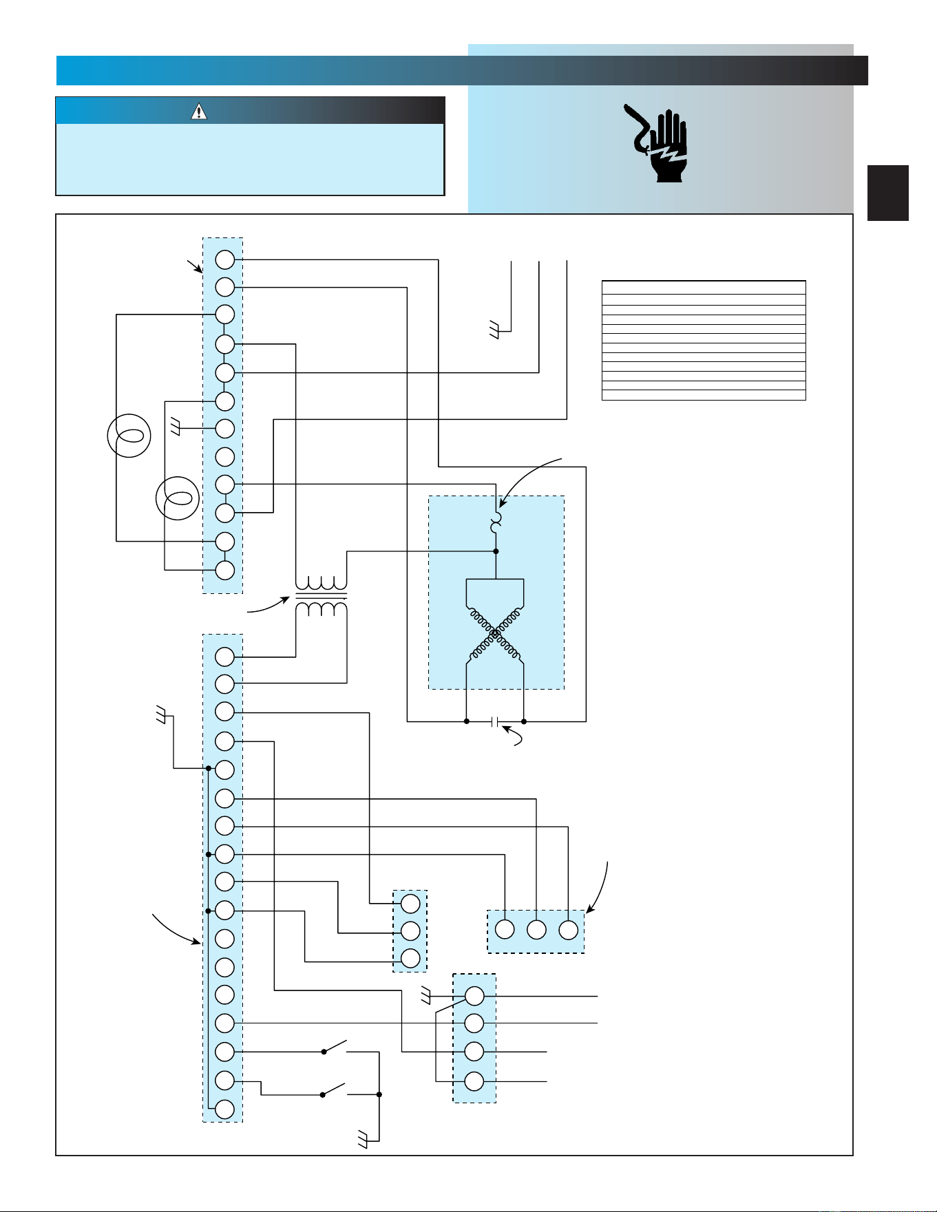
SECT 11—WIRING DIAGRAM
FOR HELP-1.800.354.3643 OR GENIECOMPANY.COM
Opening cover could cause electrical shock.
Remove power from operator prior to
removing cover.
CAUTION
1
2
3
4
5
6
7
8
9
10
11
12
3
4
5
6
7
8
9
10
11
12
13
14
15
16 17
1
2
3
1
1
2
3
2
3
4
1
2
BLACK
ORANGE
ORANGE
ORANGE
ORANGE
CLOSE / CERRAR / FERMER
OPEN / ABRIR / OUVRIR
YELLOW
YELLOW
WHITE
WHITE
WHITE
WHITE
WHITE
STRIPED
STRIPED
BLACK
BLACK
PURPLE
GREEN
BLUE
BLUE
BLACK = NEGRO = NOIR
BLUE = AZUL = BLEU
BROWN = MARRON = BRUN
GREEN = VERDE = VERT
GREY = GRIS = GRIS
ORANGE = NARANJA = ORANGE
PURPLE = MORADO = POURPPRE
RED = ROJO = ROUGE
RED / WHITE = ROJO / BLANCO = ROUGE / BLANC
STRIPED = RAYAS = RAYE
YELLOW = AMARILLO = JAUNE
RED / WHITE
RED
RED
GREY
GREY
BROWN
ORANGE
GREEN
GREEN
GREEN
GREEN
OPEN
ABRIR
OUVRIR
CLOSE
CERRAR
FERMER
LIGHTS
LUZES
LAMPES
WHITE
GREEN
POWER CORD
CORDON DE ALIMENTACION
CABLE D'ALIMENTATION
SEQUENCEUR
PRIMAIRE
SECUENCIADOR
PRIMARIO
PRIMARY
SEQUENCER
MOTOR
MOTOR
MOTEUR
DETECTEUR
DU R/MIN
DETECTOR
DE FREQUENCIA
DE ROTACION
RPM
SENSOR
WALL CONTROL
CONTROL DE PARED
COMMANDE DE MURAL
RADIO CONNECTOR
CONEXION DE RADIO
CONNECTEUR RADIO
STB SYSTEM
SISTEMA DE STB
SYSTEME DU STB
TERMINAL STRIP
RERMINALES
BORNES
MOTOR CAPACITOR
CONDENSADOR
CONDENSATEUR DU MOTEUR
THERMAL PROTECTOR
PROTECTOR TERMICO
PROTECTEUR THERMIQUE
PRIMARY
PRIMARIO
PRIMAIRE
SECONDARY
SECUNDARIO
SECOMDAIRE
TRANSFORMER
TRANSFORMADOR
TRANSFORMATEUR DE COURANT
BOTTIER DE
SEQUENCEUR
SEQUENCIADOR
PRIMARIO
SEQUENCER
HOUSING
(Vcc)
(SIGNAL)
(Vcc)
(TRIP)
(STB SYSTEM / SISTEMA DE STB)
(SYSTEME DU STB)
(COMMAND / MANDAR / COMMANDE)
COLOR LEGEND
ELECTRICAL SHOCK

B
The Genie Company
Professional Access Systems
LIMITED WARRANTY
Sistemas de acceso
profesional de Genie Company
GARANTíA LIMITADA
LA GARANTIE DE LA Systémes
d'accès Professionnels The
Genie Company
What is covered: Any defect in material and workmanship from
personal, normal household use in accordance with the
Owner’s Manual.
For how long: . . . . . . . .
H4000A-2 Series. . . Motor 10 years and all other parts 2 years.
H6000A-2K Series . Motor 15 years and all other parts 3 years.
IS525 Series . . . . . . Motor 2 years and all other parts 2 years.
IS550-1 Series . . . . Motor 7 years and all other parts 2 years.
IS550-2 Series . . . . Motor 10 years and all other parts 2 years.
IS550-2X Series . . . Motor 12 years and all other parts 2 years.
IS850-2M Series. . . Motor Lifetime* and all other parts 3 years.
IS900-1 Series . . . . Motor 10 years and all other parts 2 years.
IS900-2 Series . . . . Motor Lifetime* and all other parts 2 years.
IS920 Series . . . . . Motor Lifetime* and all other parts 2 years.
ISL950 Series . . . . Motor Lifetime* and all other parts 3 years.
ISL980 Series . . . . . Motor and all other parts Lifetime*.
CM7600 Series . . . . Motor 10 years and all other parts 3 years.
CM8600 Series . . . . Motor Lifetime* and all other parts 5 years.
PRO 95 Series. . . . . Motor and all other parts Lifetime*.
*Lifetime warranty - warranted for as long as you own your home.
Who Gets the Warranty: The warranty is limited to the
consumer who originally purchased the product.
Geographic Scope: This warranty applies only to Genie
products purchased in the United States and Canada.
What we will do: If your Genie product is defective, we will
send replacement parts or, at our option, replace it at no charge
to you. If we send replacement parts for your Genie product, we
may use new or reconditioned replacement parts. If we choose
to replace your Genie product, we may replace it with a new or
reconditioned one of the same or similar design.
Limitations: IMPLIED WARRANTIES, INCLUDING THOSE OF
FITNESS FOR A PARTICULAR PURPOSE AND MERCHANTABILITY
(AN UNWRITTEN WARRANTY THAT THE PRODUCT IS FIT FOR
ORDINARY USE) ARE LIMITED TO ONE YEAR FROM DATE OF
PURCHASE. GENIE WILL NOT PAY FOR; LOSS OF USE OF
YOUR GENIE PRODUCT OR PROPERTY DAMAGE CAUSED BY
YOUR GENIE PRODUCT OR ITS FAILURE TO WORK; ANY
SPECIAL, INCIDENTAL OR CONSEQUENTIAL DAMAGES; ANY
DAMAGES RESULTING FROM MISUSE OR MODIFICATION OF
YOUR GENIE PRODUCT.
Some states and provinces do not allow limitations on how long
an implied warranty lasts or the exclusion of incidental or
consequential damages, so the above exclusions may not apply.
How to get Warranty Service: To get warranty service for your
Genie product, you must provide proof of date, and place of
purchase of the product.
1. Do-It-Yourself-Service: Call Genie Consumer Connection toll
free at 1-800-354-3643. Trained Genie representatives will assist
in diagnosing the problem and will arrange to supply you with
required parts for do-it-yourself repairs. Trained service
representatives are available Monday-Friday, 8:00 AM - 11:00
PM, and on Saturday, 11:00 AM -8:00 PM Eastern Time
(subject to holidays.)
2. Service From Authorized Dealers: You can obtain the name of
a Genie authorized dealer by calling the Genie Consumer
Connection at 1-800-654-3643. If an authorized dealer provides
warranty service,
Genie will not reimburse you or otherwise be
responsible
for those charges.
Your choice of any one of the above described service options is
your remedy under this warranty.
What This Warranty Does Not Cover: This warranty does not
cover batteries (which are considered replaceable parts,)
installation, commercial use, defects resulting from accidents,
damage while in transit to our service location or damage
resulting from alterations, misuse or abuse, lack of proper
maintenance, unauthorized repair or modifications of the
product, affixing of any attachment not provided with the
product, programming of the Remote Control Devices,
Safe-T-Beam® adjustment/cleaning, staples through wiring,
pinched or broken wires, Carriage disengaged, Force Control
adjustments, door out of balance, broken springs or cables,
power outages, use of extension cords, missing or damaged
parts on discounted, clearanced, final sale or taped cartons,
phantom operations (labor is not covered if Opener is
functioning properly while technician is in garage), fire, flood,
acts of God, or failure to follow the Owner's Manual.
This warranty is the only one we will give on your Genie
product, and it sets forth all our responsibilities regarding
your Genie product. There are no other express warranties.
State and Province Rights: This warranty gives you specific
legal rights, and you may also have other rights that vary from
state to state and province to province.
Lo que está cubierto: todo defecto en materiales y mano de obra en el
uso doméstico personal y normal de acuerdo con el Manual del
Propietario.
Duración:
Serie H4000A-2 . . . Motor 10 años y todas las demás piezas 2 años.
Serie H6000A-2K . . Motor 15 años y todas las demás piezas 3 años.
Serie IS525 . . . . . . Motor 2 años y todas las demás piezas 2 años.
Serie IS550-1. . . . . Motor 7 años y todas las demás piezas 2 años.
Serie IS550-2. . . . . Motor 10 años y todas las demás piezas 2 años.
Serie IS550-2X. . . . Motor 12 años y todas las demás piezas 2 años.
Serie IS850-2M . . . Motor Vitalicia* y todas las demás piezas 3 años.
Serie IS900-1. . . . . Motor 10 años y todas las demás piezas 2 años.
Serie IS900-2. . . . . Motor Vitalicia* y todas las demás piezas 2 años.
Serie IS920 . . . . . . Motor Vitalicia* y todas las demás piezas 2 años.
Serie ISL950 . . . . . Motor Vitalicia* y todas las demás piezas 3 años.
Serie ISL980 . . . . . Motor y todas las demás piezas Vitalicia*.
Serie CM7600 . . . . Motor 10 años y todas las demás piezas 3 años.
Serie CM8600 . . . . Motor Vitalicia*y todas las demás piezas 5 años.
Serie PRO 95 . . . . . Motor y todas las demás piezas Vitalicia*.
*Garantía Vitalicia – se garantiza mientras usted sea el propietario de
su casa.
¿Quién obtiene la garantía? La garantía está limitada al consumidor
que compró originalmente el producto.
Alcance geográfico: Esta garantía se aplica sólo a los productos Genie
comprados en los Estados Unidos y Canada.
Lo que haremos: Si su producto Genie es defectuoso, mandaremos el
reemplazo los partes o, a opción nuestra, lo reemplazaremos sin cargo
alguno para usted. Si mandamos el reemplazo las partes su producto
Genie, podemos usar piezas de reemplazo nuevas o reacondicionadas.
Si optamos por cambiar su producto Genie, podemos cambiarlo por
uno nuevo o reacondicionado del mismo diseño o similar.
Limitaciones: LAS GARANTÍAS IMPLÍCITAS, INCLUYENDO
AQUELLAS DE CONVENIENCIA PARA UN PROPÓSITO PARTICULAR Y
COMERCIABILIDAD (UNA GARANTÍA NO ESCRITA QUE EL
PRODUCTO ES APROPIADO PARA USO ORDINARIO) ESTÁN
LIMITADAS A UN AÑO A PARTIR DE LA FECHA DE COMPRA. GENIE
NO PAGARÁ POR PÉRDIDA DEL USO DE SU PRODUCTO GENIE O
POR DAÑOS DE PROPIEDAD CAUSADOS POR SU PRODUCTO GENIE
O POR LA FALLA DE TRABAJAR; POR DAÑOS CUALESQUIERA
ESPECIALES, INCIDENTALES O EMERGENTES; POR DAÑOS
RESULTANTES DEL MAL USO O LA MODIFICACIÓN DE SU
PRODUCTO GENIE.
Algunos estados y provincias no permiten limitaciones del tiempo que
dura la garantía implícita o la exclusión de daños incidentales o
circunstanciales, entonces puede que las limitaciones de arriba no se
apliquen.
Cómo obtener servicio de garantía: Para obtener servicio de garantía
para su producto Genie, usted debe proporcionar prueba de la fecha y
lugar de la compra del producto.
1. Servicio de bricolaje:
Llamar sin cargo a la conexión del consumidor
de Genie, marcando el 1-800-354-3643. Representantes entrenados de
Genie le asistirán en diagnosticar el problema y harán arreglos para sum-
inistrarle las piezas necesarias para las reparaciones de bricolaje o sea que
usted mismo haga. Los representantes de servicio entrenados están
disponibles de lunes a viernes, de 8:00 a.m. a 11:00 p.m. y los sábados
de 11:00 a.m. a 8:00 p.m. hora del Este (sujeto a feriados).
2. Servicio de distribuidores autorizados: Usted puede obtener el
nombre del distribuidor autorizado de Genie llamando a la conexión del
consumidor de Genie, marcando el 1-800-654-3643. Si un
distribuidor autorizado extiende una garantía de servicio, Genie no le
reembolsará a usted ni será responsable por esos cargos.
Su elección de cualesquiera de las opciones de los servicios descritos
arriba es el recurso que tiene bajo esta garantía.
Qué Esta Garantía no Cubre: Esta garantía no cubre baterías
(que considera las partes reemplazables,) la instalación, el uso
de la propaganda, los defectos resultando de accidentes, el
daño mientras en tránsito a nuestra ubicación del servicio o
resultar de daño de modificaciones, el maltrato o el abuso, la
falta de la conservación apropiada, la reparación o las
modificaciones no autorizadas del producto, poner de ninguna
fijación no proporcionó con el producto, programar de los
Dispositivos del Mando a distancia, de T de Rayo Segura® el
ajuste/limpiar,Los alambres pellizcados o rotos, el Coche soltó,
los ajustes del Control de la Fuerza, la puerta fuera de
equilibrio, los primaveras o los cables rotos, las fallas del poder,
el uso de cuerdas de extensión, perdiendo o las partes dañadas
en descontado, clearanced, la venta final o los cartones
grabados, las operaciones fantasmales (el trabajo no se cubre
si el Abrelatas funciona apropiadamente mientras técnico está
en el garaje), el fuego, la inundación, los actos de la naturaleza,
o el fra.
Esta garantía es la única que daremos a su producto Genie, y
estipula todas nuestras responsabilidades con respecto a su
producto Genie. No hay otras garantías expresas.
Derechos de estados y provincias: Esta garantía le otorga derechos
legales específicos y puede que usted tenga también otros derechos
que varían de estado a estado y de provincia a provincia.
Ce qu’elle couvre: toute défectuosité de matériau et tout défaut de fab-
rication constatés pendant l’utilisation normale du produit par un indi-
vidu à son domicile en conformité avec le Manuel de l’utilisateur.
Pendant combien de temps:
Série H4000A-2 . . . Moteur 10 ans et toutes les autres pièces 2 ans.
Série H6000A-2K . . Moteur 15 ans et toutes les autres pièces 3 ans.
Série IS525. . . . . . . Moteur 2 ans et toutes les autres pièces 2 ans.
Série IS550-1 . . . . . Moteur 7 ans et toutes les autres pièces 2 ans.
Série IS550-2 . . . . . Moteur 10 ans et toutes les autres pièces 2 ans.
Série IS550-2X . . . . Moteur 12 ans et toutes les autres pièces 2 ans.
Série IS850-2M . . . Moteur à vie* et toutes les autres pièces 3 ans.
Série IS900-1 . . . . . Moteur 10 ans et toutes les autres pièces 2 ans.
Série IS900-2 . . . . . Moteur à vie*et toutes les autres pièces 2 ans.
Série IS920. . . . . . . Moteur à vie*et toutes les autres pièces 2 ans.
Série ISL950. . . . . . Moteur à vie*et toutes les autres pièces 3 ans.
Série ISL980. . . . . . Moteur et toutes les autres pièces à vie*.
Série CM7600. . . . . Moteur 10 ans et toutes les autres pièces 3 ans.
Série CM8600. . . . . Moteur à vie*et toutes les autres pièces 5 ans.
Série PRO 95 . . . . . Moteur et toutes les autres pièces à vie*.
*Garantie à vie – Garanti tant que vous restez propriétaire de votre
habitation.
Bénéficiaire de la garantie: La garantie est limitée au client qui a
acheté initialement le produit.
Pays couverts: Cette garantie s’applique seulement aux produits
Genie achetés aux états-Unis et Canada.
Nos conditions: Si le produit Genie est défectueux, nous enverrons
les parties de replacement ou, selon notre choix, de le remplacer
sans frais de votre part. Si nous envoyons les parties de
replacement du produit, il est possible que nous utilisions des
piéces de remplacement neuves ou reconditionnées. Si nous
décidons de remplacer le produit Genie, il est possible que nous le
remplacions avec un produit neuf ou reconditionné de conception
semblable.
Limites: LES GARANTIES IMPLICITES, Y COMPRIS LES
GARANTIES D’A-DAP-TA-TION À UN USA-GE PAR-TI-CU-LIER ET
LA GA-RAN-TIE DE VALIDITÉ MAR-CHAN-DE (UNE GARANTIE
TACITE QUE LE PRODUIT EST ADAPTÉ À L’USAGE) SONT
LIMITÉES À UN AN À COMPTER DE LA DATE D’ACHAT. GENIE
DÉCLINE TOUTE RESPONSABILITÉ EN CAS DE PERTE
D’UTILISATION DU PRODUIT OU DE DOMMAGES MATÉRIELS
CAUSÉS PAR LE PRODUIT GENIE OU PAR UN FONCTIONNEMENT
DÉFECTUEUX ; DE DOMMAGES ACCIDENTELS OU INDIRECTS ;
DE DOMMAGES ISSUS DE L’UTILISATION INCORRECTE OU DE
LA MODIFICATION DU PRODUIT GENIE.
Certains états et provinces n’autorisent pas les limites de durée
des garanties implicites ou l’exclusion des dommages accidentels
ou indirects. Dans ce cas, les exclusions ci-dessus ne
s’appliquent pas.
Comment bénéficier du service offert par la garantie: Pour
pouvoir en bénéficier, il vous faut fournir une justification de la
date et du lieu de l’achat.
1. Service pour effectuer les réparations soi-même: Appeler le
numéro sans frais du service à la clientéle Genie 1-800-354-3643.
Des agents Genie spécialisés vous aideront à diagnostiquer le
probléme et prendront les dispositions nécessaires pour vous
fournir les piéces requises afin que vous puissiez effectuer les
réparations par vous-même. Vous pouvez joindre ce service du
lundi au vendredi, de 8 h à 23 h et le samedi, de 11 h à 20 h,
heure de l’Est (sauf jours fériés)
2. Service effectué par des techniciens agréés: Appeler le service
à la clientéle Genie au 1-800-654-3643 qui vous communiquera le
nom d’un technicien agréé. Si le technicien agréé offre un service
de garantie, les frais encourus ne seront pas remboursés par Genie
et Genie ne sera pas tenu responsable du réglement des frais.
Le choix de l’une des options de service décrite ci-dessus est le
recours dont vous disposez sous cette garantie.
Que Cette Garantie Pas Couverture: Cette garantie pas piles
couverture (qui sont-ils considéré des parties remplaçables,)
installation, usage *, défauts Rayon résulter de accidents,
dommages * dans traversée à notre emplacement service ou
pas dommages qui résulte de changements, * ou abus, manque
d'entretien propre, réparation ou modifications inautorisée du
produit, apposant d'attachement ont fourni avec le produit,
programmant de H, de T de Rayon Sûr® ajustement
nettoyage,Fils pincés ou cassés, l'Attelage a déclenché, les
ajustements de Contrôle de Force, la porte d'équilibre, les
ressort ou les câbles cassés, les coupures de courant, l'usage
de rallonges, manquant ou a endommagé des parties sur
escompté, clearanced, la vente finale ou a enregistré des boîtes,
les opérations fantômes (la main-d'oeuvre n'est pas couverte si
l'Ouvre-boîte fonctionne convenablement pendant que le
technicien est dans le garage), le feu, l'inondation, les désastres
naturels, ou l'échec pour suivre le Manuel du Propriétaire.
Cette garantie est la seule garantie fournie pour le produit et fait
valoir toutes les responsabilités
qui vous incombent concernant
le produit Genie. Il n’y a pas d’autres garanties expresses.
Droits pour les êtats et les provinces: Cette garantie vous donne
des droits juridiques spécifiques; les autres droits peuvent varier
d’un êtat à l’autre et d’une province à l’autre.
Visit Our Website at:
www.geniecompany.com
Visitar “Website” nuestro en:
www.geniecompany.com
Visite “Website” notre en:
www.geniecompany.com
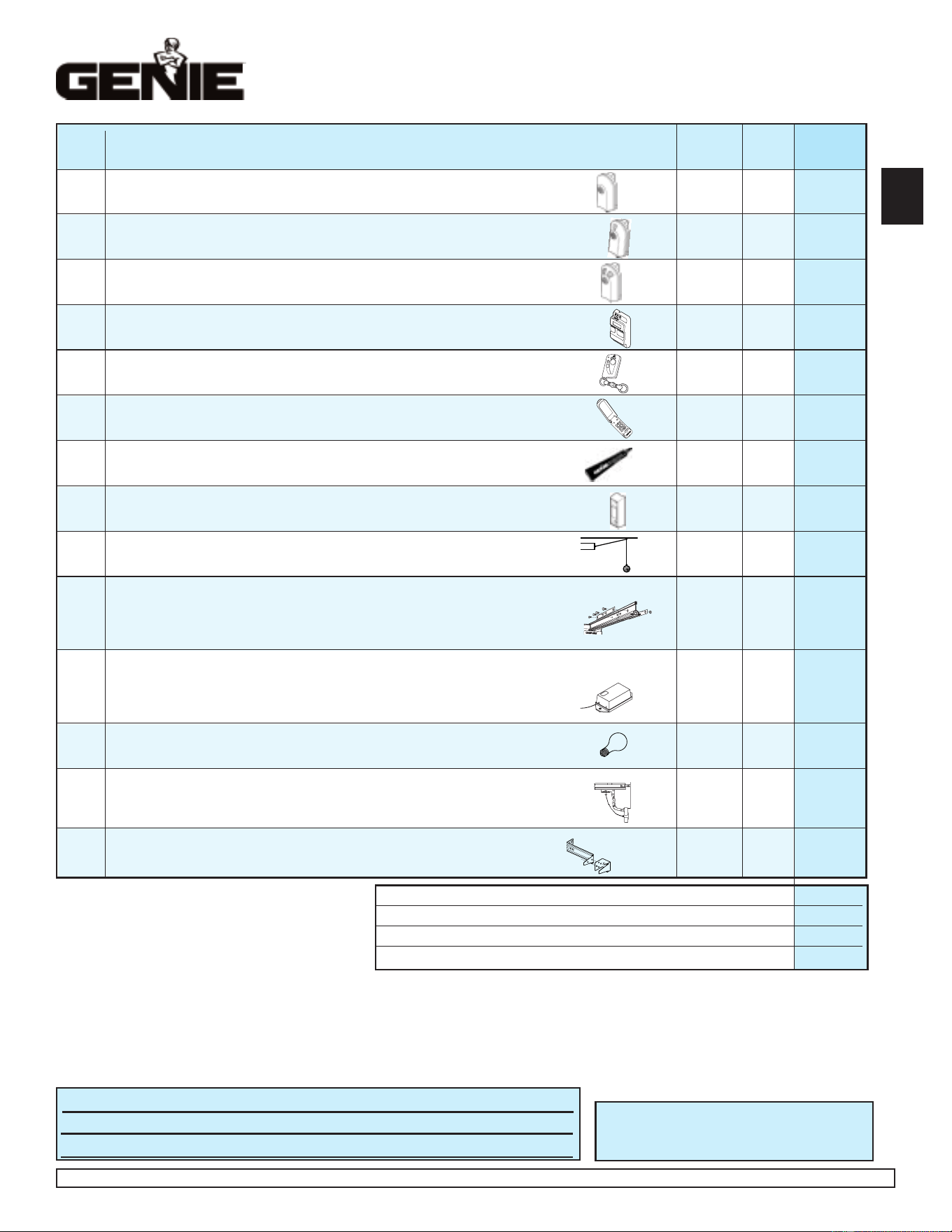
Please add local sales tax if you reside in one of the states listed.
California
Connecticut
Florida
Maryland
Massachusetts
New Jersey
Virginia
Wisconsin
TOTAL ORDER / TOTAL DEL PEDIDO / COMMANDE TOTALE $
SHIPPING & HANDLING / FLETE Y MANEJO / MANUTENTION ET EXPÉDITION $ 5.00
STATE SALES TAX / IMPUESTO DE VENTAS ESTATAL / TAXE DE VENTE $
GRAND TOTAL / GRAN TOTAL / TOTAL GLOBAL $
Garage Door Operator Accessories Order Form
Formulario de pedido de accesorios para abridores de puertas de garaje
Formulaire de commande des accessoires pour ouvre-porte de garage
MODEL DESCRIPTION / PRODUCT CODE PRICE (US$)* QTY. SUBTOTAL
MODELO DESCRIPCIÓN / CÓDIGO PRECIO* CANTIDAD SUBTOTAL
MODÈLE DESCRIPTION / CODE DU PRODUIT PRIX ($ US)* QTÉ SOUS-TOTAL
Deluxe Remote Control with Intellicode
®
- Allows remote operation of garage door.
GIT-1
Controlador remoto de lujo con Intellicode
®
- Proporciónar operación remoto de la puerta del garaje.
33069R $34.95
Télécommande de luxe avec Intellicode
®
- Permettre opération éloign´´de porte de garage.
2-Button Remote Control with Intellicode
®
- Allows remote operation of 2 garage doors.
GIT-2
Controlador remoto de 2 funciones con Intellicode
®
- Proporciónar operación remoto de dos las puertas del garaje. 33069S $44.95
Télécommande à 2 fonctions avec Intellicode
®
- Permettre opération éloign´ deux portes de garage.
3-Button Remote Control with Intellicode
®
- Allows remote operation of 3 garage doors.
GIT-3
Controlador remoto de 3 funciones con Intellicode
®
- Proporciónar operación remoto de tres las puertas del garaje. 33069T $49.95
Télécommande à 3 fonctions avec Intellicode
®
- Permettre opération éloign´ trois portes de garage.
Lighted Wall Console - Operates Garage Door. Independent light control. Security vacation lock.
GPWC
-
Consola de pared de 3 funciones - Acciona la puerta del garaje. Control de luz independiente. Cerradura de seguridad para vacaciones. 34292R $34.95
2WLB
Console murale à trois fonctions - Actionne la porte de garage. Commande d’éclairage indépendante. Interrupteur de verrouillage de sécurité.
3-Button Mini Remote Control with Intellicode
®
- Fits easily into pocket or purse.
GMI-3
Minicontrolador remoto de 3 funciones con Intellicode
®
- Cave fácilmente en el bolsillo o cartera.
34909R $39.95
Mini télécommande à 3 fonctions avec Intellicode
®
- se glisse dans la poche de veston ou le sac à main.
Wireless Keypad Entry System - Operates Intellicode
®
Garage Door Operators without Remote Control or key.
GWKP Sistema de entrada por teclado numérico inalámbrico - Acciona los abridores de puertas de garaje Intellicode
®
sin control remoto o llave.
35282R $49.95
Système d’ouvre-porte de garage à clavier sans fil - Actionne les ouvre-porte de garage avec Intellicode
®
sans télécommande ni clé.
(3) 1/4 oz. tubes Screw Grease - Ensures proper equipment wear protection.
GLU-3 (3) 1/4 once lubricante de tornillo accionar - Asegura componente correcto protección por deterioro. 35164R $1.95
La onza 1/4 lubricant de la vis (3)- Garantir componant exact par systéme défense vers user.
Universal Wall Button - Provides additional convenient inside operation of Door.
GWB Botón de pared universal - Proporciona operación conveniente de la puerta desde el interior. 34960R $04.95
Bouton mural universel - Actionne l’ouvre-porte de l’intérieur du garage.
Perfect Stop
®
- Ensures perfect parking.
GPS-5 Stop Perfecto
®
- Asegura el estacionamiento perfecto.
34964R $04.95
Butoir Perfect Stop
®
- Permet de stationner à la perfection dans le garage.
Screw Drive Extension Kit - Eighteen inch Extension to increase travel of Screw Drive Operator to accommodate eight foot door.
GSX-8
Juego de extensión deslizante de Screw Drive - Una extensión de 18 pulgadas para aumentar la carrera de un abridor deslizable de tornillo,
para acomodar una puerta de 8 pies (2,43 m.).
$34.95
Nécessaire de rallonge du Screw Drive - Rallonge de 30 dm (18 po) prolongeant la course de l’ouvre-porte Screw Drive pour une porte
33523R
de 2,4 m (8 pi) de hauteur.
Universal Conversion Kit - Converts any Garage Door Operator to a secure radio signal system. Kit includes a Remote Control, Receiver and Transformer..
GIRU-1T
Juego de conversión universal - Convierte cualquier abridor de puerta de garaje a un sistema de señal de radio seguro. El juego incluye
un control remoto de abridor de puerta de garaje, receptor y transformador.
33154R $49.95
Nécessaire de conversion universel - Transforme tout ouvre-porte de garage en système de sécurité à signal radio. Comprend une
télécommande d’ouvre-porte de garage, un récepteur et un transformateur.
60 WATT Enhanced/Rough Service Light Bulb - Ensures proper equipment compatability.
LIGHTBULB
Bombilla de 60 Vatios - Asegura componente correcto de sistema.
26210A.S $2.95
Éclairage de 60 WATT - Garantir componant exact par systéme.
Emergency Release Kit - Provides access to garage from outside in the event of an electrical power failure.
GER-2
Juego de pica-porte de pestillo - Permitir entrtada desde por fuera de garaje porque corte de eléctric.o
34963R $29.95
Nécessaires de Déclenchement de secours - Le nécessaire de déclenchement de secours est conçupour vous permettre d’accéder
à votre garage depuis l’extérieur en cas de panne de courant et lorsqu’il.
STB Adapter Brackets (2) - Used in conjunction with standard STB mounting brackets, they provide additional clearance along with mounting options.
ADAPTER
Bras adaptador por STB(2) - Usado con bras normal por STB, proveer espacio adicional.
34439R.S $4.95
BRACKET
Supports raccord du STB (2) - Se servir en compagnie de supports normal du STB, assurer espace supplémentaire.
MAIL ORDER FORM TO:
ENVIAR HACER UN PEDIDO DE MERCANCIA A:
METTRE À LA POSTE LE ARRANGEMENT À:
The Genie Company
22790 Lake Park Blvd.
Alliance, Ohio 44601
NAME / NOMBRE / NOM
ADDRESS / DIRECCIÓN / ADRESSE
CITY / CIUDAD / VILLE STATE / ESTADO / ÉTAT ZIP / CÓDIGO POSTAL / CODE POSTAL
SHIP ORDER TO: / ENVIAR MERCANCIA CON: / EXPÉDIER MARCHANDISE POUR:
Prices subject to change without notice
*
El precio está sujeto a cambios sin aviso
*
Les prix peuvent subir des modifications sans préavis
®
AVAILABLE AT YOUR LOCAL DISTRIBUTOR—DISPONIBLE POR SU DISTRIBUIDOR LOCAL—DISPONIBLE AUPRÈS DE VOTRE DISTRIBUTEUR LOCAL
No C.O.D. shipments. Please include check or money order, do not send cash.
Allow 3-4 weeks for delivery. We accept Visa or Mastercard phone orders.
1.800.354.3643. Please have part number and credit card ready
No se aceptan pedidos de pago contra entrega (COD). Sírvase incluir su cheque o
giro postal; no envíe dinero en efectivo. Concédanos 3 a 4 semanas para la entrega.
Aceptamos pedidos telefónicos de Visa o Mastercard. 1.800.354.3643. Sírvase tener
listos los números del modelo y de la tarjeta de crédito.
Pas d’expédition contre remboursement.Veuillez inclure un chèque ou un mandat
bancaire. N’envoyez pas d’argent comptant. Accordez de 3 à 4 semaines pour la
livraison. Nous acceptons les commandes par téléphone avec paiement par carte de
crédit Visa ou Mastercard. 1.800.354.3643. Ayez sous la main le numéro de la pièce et
celui de la carte de crédit.
Georgia
Illinois
Indiana
New York
Ohio
Tennessee
3
DEF
1
2
456
7
8
9
0
GHI
J
K
L
MNO
PQR
S
T
U
V
WXYZ
9V
C
PHOTOCOPY THIS PAGE TO USE FOR ORDERING / FOTOCOPIAR LA PAGINA POR USAR CUANDO HACER EN PEDIDO / RENDRE APPAREIL PHOTOSTAT DU PAGE POUR USAGE A DISPOSITION