Loading ...
Loading ...
Loading ...
Ifthetractorturnstighterinonedirectionthanthe
other,oriftheballjointsarebeingreplaceddueto
damageorwear,thesteeringdraglinksmayneedto
beadjusted.Adjustthedraglinkssothatequal
lengthsarethreadedintotheballjointsonbothsides.
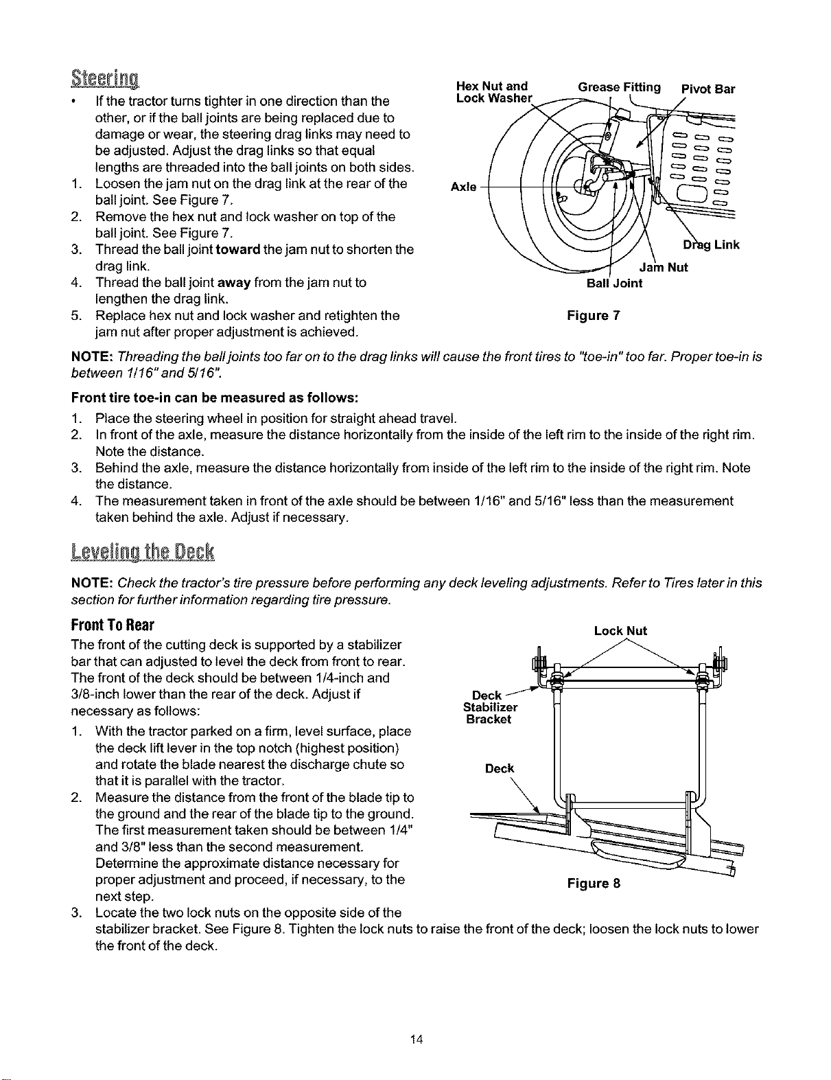
1. Loosenthejamnutonthedraglinkattherearofthe
balljoint.SeeFigure7.
2. Removethehexnutandlockwasherontopofthe
balljoint.SeeFigure7.
3. Threadtheballjointtowardthejamnuttoshortenthe
draglink.
4. Threadtheballjointawayfromthejamnutto
lengthenthedraglink.
5. Replacehexnutandlockwasherandretightenthe
jamnutafterproperadjustmentisachieved.
Hex Nut and
Lock Washer
Axle
Grease Fitting Pivot Bar
Ball Joint
Figure 7
Link
Nut
NOTE: Threading the ball joints too far on to the drag links will cause the front tires to "toe-in" too far. Proper toe-in is
between 1/16" and 5/16".
Front tire toe-in can be measured as follows:
1. Place the steering wheel in position for straight ahead travel.
2. Infront of the axle, measure the distance horizontally from the inside of the left rim to the inside of the right rim.
Note the distance.
3. Behind the axle, measure the distance horizontally from inside of the left rim to the inside of the right rim. Note
the distance.
4. The measurement taken in front of the axle should be between 1/16" and 5/16" less than the measurement
taken behind the axle. Adjust if necessary.
LevelingtheDeck
NOTE: Check the tractor's tire pressure before performing any deck leveling adjustments. Refer to Tires later in this
section for further information regarding tire pressure.
FrontToRear
The front of the cutting deck is supported by a stabilizer
bar that can adjusted to level the deck from front to rear.
The front of the deck should be between 1/4-inch and
3/8-inch lower than the rear of the deck. Adjust if
necessary as follows:
1. With the tractor parked on a firm, level surface, place
the deck lift lever in the top notch (highest position)
and rotate the blade nearest the discharge chute so
that it is parallel with the tractor.
2. Measure the distance from the front of the blade tip to
the ground and the rear of the blade tip to the ground.
The first measurement taken should be between 1/4"
and 3/8" less than the second measurement.
Determine the approximate distance necessary for
proper adjustment and proceed, if necessary, to the
next step.
3. Locate the two lock nuts on the opposite side of the
Deck _
Stabilizer
Bracket
Deck
Lock Nut
Figure 8
stabilizer bracket. See Figure 8. Tighten the lock nuts to raise the front of the deck; loosen the lock nuts to lower
the front of the deck.
14
Loading ...
Loading ...
Loading ...