
Loading ...
Loading ...
Loading ...
14
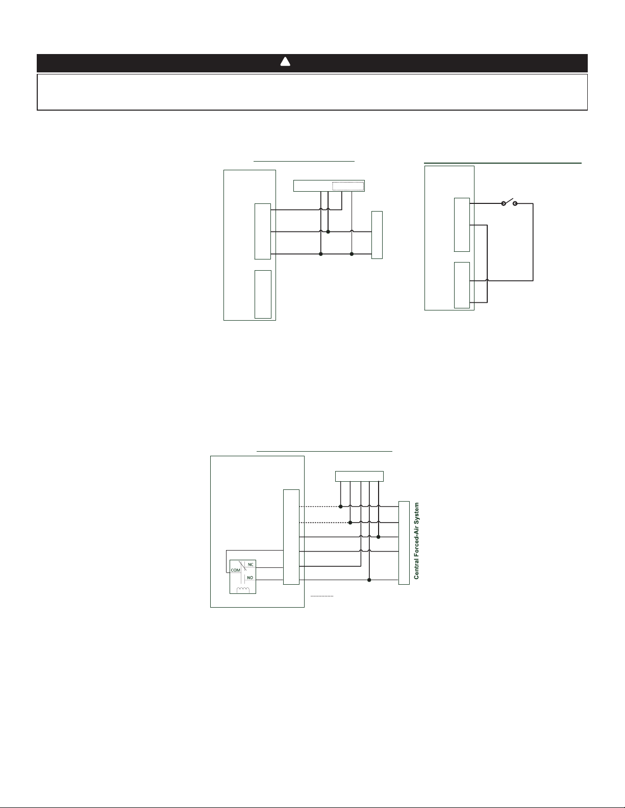
3.3.2 UNIT INTERCONNECTION WITH CENTRAL FORCED-AIR SYSTEM (R/C/G/GF)
These connections must be done if you want the unit to force the central forced-air system blower operation when ventilating (refer to
solid lines in above diagram).
NOTE : These connections are required for installation configuration T-4. Refer to section 2.2 for more details.
3.3.3 SYNCHRONIZATION WITH CENTRAL FORCED-AIR SYSTEM FUNCTION
The Virtuo technology allows synchronizing the unit operation with the central forced-air system operating time. It prevents unnecessary
central forced-air system operating time while providing a better air distribution.
To use this function, W and Y connections must be added to R and C connections to inform the unit that the central forced-air system is
running (refer to dotted lines in above diagram).
Air Exchanger PCB
Terminal Blocks
Y
W
C
G
R
Y W G R C
Central Forced-Air System Thermostat
Wiring Options with Central Forced-Air System
Vent
Y
W
C
Gf
G
R
J13
Internal
Logic
Optional Wiring for Synchronization
Never connect a 120-volt AC circuit to the terminals of the central forced-air system interlock (standard wiring). Only use the low voltage
class 2 circuit of the central forced-air system blower control. The unit is designed for low voltages only. Connecting the unit on 120-volt
circuit would damage it instantly.
WARNING
!
3.3 CONNECTION TO THE CENTRAL FORCED-AIR SYSTEM
3.3.1 UNIT OPERATION USING A DRY CONTACT CONNECTION
This unit can be controlled by any dry contact connection such as the thermostat equipped with an optional ventilation output.
Y
W
C
G
R
Y W G R C Acc+ Acc-
Central Forced-Air System Thermostat
Central Forced-Air System
Wiring for Dry Contact Connection
1
1- External switch or any Dry-contact can be used to
activate Vent input if not available on the Thermostat
Air Exchanger
Terminal Blocks
Alternate Wiring for Dry Contact Independent Installation
Vent
Y
W
C
Gf
G
R
J13
OVR
LED
12V
D-
D+
GND
J9
External Switch or any
alternate Dry-Contact
Air Exchanger
Terminal Blocks
Vent
Y
W
C
Gf
G
R
J13
OVR
LED
12V
D-
D+
GND
J9
Note : Synchronization with a central forced-air system
with W and Y is not available with this configuration.
1 - External switch or any dry contact can be used to activate vent input if not
available on the thermostat. Some thermostats offer a single wire 24VAC output
for accessory ventilation. It can be directly connected to vent input and therefore
the Acc- / R connection is not required.
Once wired, unit will toggle between the
Standby mode when contact is opened and
the selected mode when contact is closed.
Choose among these 4 configurations:
minimum (unit operating in MIN speed),
intermittent (unit operating in MIN speed
20 min/hr then as per INT configuration
selection for 40 min), auto* (unit operating
according to outdoor temperature) and
maximum (unit operating in MAX speed)
in DRY option on the LCD screen when the
VENT contact is activated. Refer to section 5
for more details.
* In auto mode, the unit will operate as
follows:
• Less than -13°F = 10 min/hr
• -13°F to 19°F = 20 min/hr
• 19°F to 50°F = 40 min/hr
• 50°F to 77°F = MIN speed
• 77°F to 82°F = 30 min/hr
• 82°F to 91°F = 20 min/hr
• Above 91°F = 10 min/hr
NOTE : This dry contact option will override the main wall control so we do not recommend
the use of a wall control with this type of connection.
NOTE : Following ducting installation configuration and temperature conditions, it may be
necessary for the unit to operate continuously. Refer to section 2.2 for more details.
Loading ...
Loading ...
Loading ...