Loading ...
Loading ...
Loading ...
ENGLISH
5
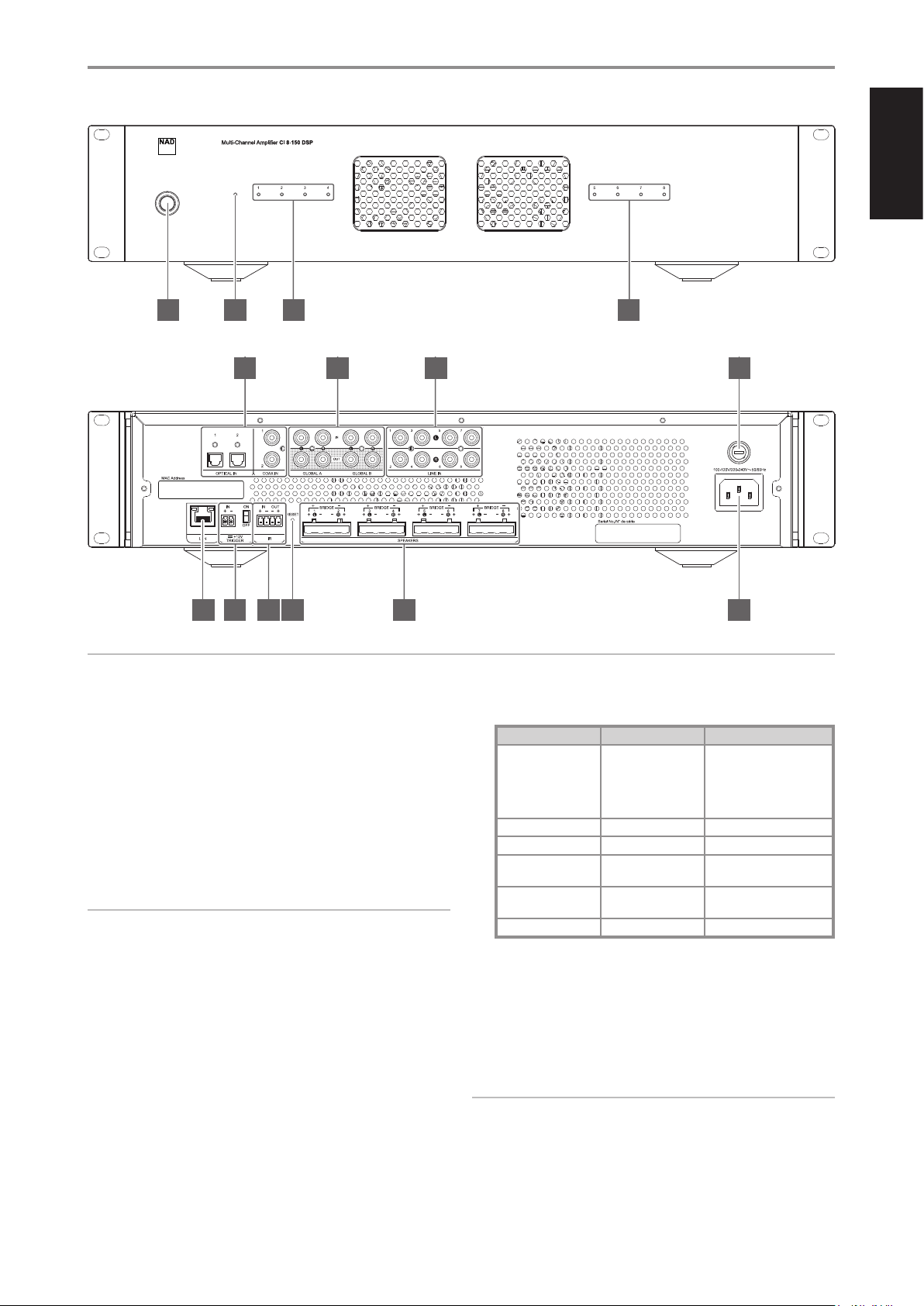
IDENTIFICATION OF CONTROLS
1 POWER BUTTON
• Press this button to switch ON CI 8-150 from standby mode. All
eight LINE INPUT LED indicators will turn red for about 10 seconds,
briey all blue and then blue for those LINE INPUT channels with
active line input signal or no light (except Standby LED) in the
absence of any active line input signal. The 10 seconds delay in
powering up is intended for system power stability and security
self-check.
• Pressing the Power button again turns the unit back to standby
mode. The Standby LED indicator will turn from blue to amber.
NOTE
“Power Mode” (Settings - Power Settings - Power Mode) must be set to
“Power Button” for the unit to power up via front panel Power button.
2 STANDBY LED
• This indicator will light up amber when CI 8-150 is at standby mode.
When CI 8-150 is powered up from standby mode, this indicator will
illuminate blue.
STANDBY AND LINE INPUT LED STATUS INDICATORS
DESCRIPTION STANDBY LED STATUS LINE INPUT LED 1-8 STATUS
Operating mode Blue
Corresponding Line Input LED
indicator is solid blue with
active line input signal or no
light in the absence of any
active line input signal.
Standby mode Amber O, no light
System reboot Flashing amber Red $ Blue $ O, no light
Overvoltage or under
voltage
Red O, no light
AMP current error Blue
Corresponding channel LED
is red.
AMP DC error Red O, No light
3 LINE INPUT (1 – 8) LED INDICATORS
• LINE INPUT channels with active input signal will have their
corresponding front panel LINE INPUT LED indicators illuminated in blue.
• If there is no active input signal connected to a particular LINE
INPUT, the corresponding front panel LINE INPUT LED indicator will
not light up.
IMPORTANT NOTICE
If the selected source is GLOBAL A and/or GLOBAL B and there is an
active input signal at either GLOBAL input terminal, all eight LINE INPUT
LED indicators will illuminate at the same time.
ATTENTION!
Please ensure that the CI 8-150 is powered o or unplugged from the mains power outlet before making any connections. It is also advisable to power
down or unplug all associated components while making or breaking any signal or AC power connections.
© NAD CI 8-150 DSP
1 2 3 3
© NAD CI 8-150 DSP
8 9 10 11 12 13
4 5 6 7
Loading ...
Loading ...
Loading ...