Loading ...
Loading ...
Loading ...
ENGLISH
OPERATION
13
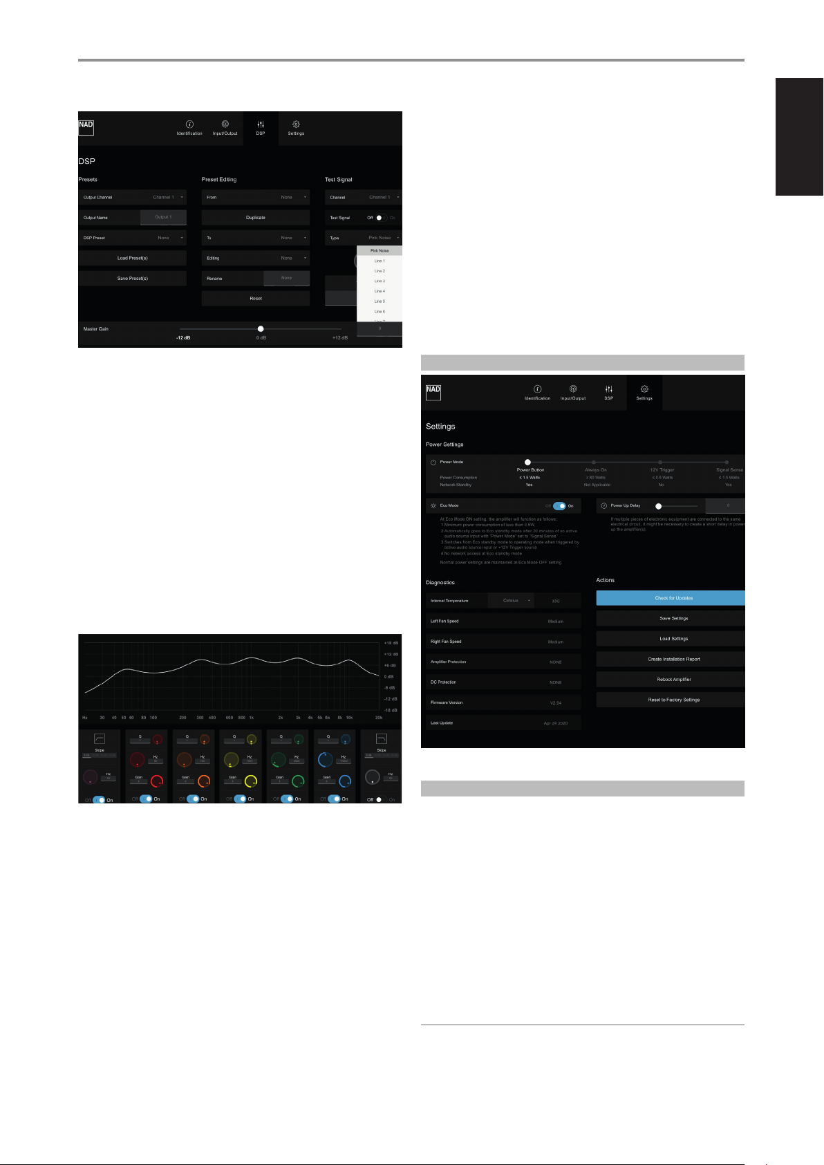
TYPE
• The test signal can be a pink noise generator or actual input signal from
any of the input channels. Select from the drop down tab Pink Noise
or Line1 to Line 8 to serve as test signal for specic channel or for ALL
channels.
• Pink noise is useful in setting up audio and equalization levels.
VOLUME
• Grab the pointer of the VOLUME knob icon and rotate to adjust test
signal audio level. The corresponding numerical value of the adjusted
test signal audio level is reected below the knob icon.
MASTER GAIN
• Adjusting Master Gain level will be simultaneously eective to all
output channels. Drag the slider icon to set Master Gain level within
±12 dB range. The corresponding numerical value of adjusted Master
Gain level is reected beside the slider icon. You can also type directly
desired Master Gain level in the section beside the slider icon.
Frequency Response Graph (sample only to show response when you turn ON each parameter)
SLOPE
• Slope refers to how abruptly frequencies are attenuated by the lter
once the cuto frequency is passed. Slope is quantied in decibels per
octave (dB/octave). Available selectable lter (roll o) slope values are
-6dB, -12dB, -18dB and -24dB per octave.
FREQ Hz
• Grab the pointer of the “Hz” knob icon and rotate to set the frequency
level where the lter will be enabled. The frequency range available
is 20 Hz up to 20 kHz. The corresponding numerical value of adjusted
frequency level is reected beside the knob icon. You can also type
directly desired frequency level in the section beside the “Hz” knob icon.
Q
• “Q” setting refers to the depth the bandwidth can be adjusted. ”Q” level
is from 0.1 up to 24. Bandwidth is wider at lower Q level and narrower
with higher Q level.
GAIN
• Grab the pointer of the “Gain” knob icon and rotate to set the dB level
the selected frequency can be increased or decreased. Gain level can
be set up to 12 dB. The corresponding numerical value of adjusted
dB level is reected beside the knob icon. You can also type directly
desired dB level in the section beside the “Gain” knob icon.
OFF/ON
• Enable (On) or disable (O ) the Slope, Q, Hz and Gain settings by
selecting “On” or “O” under their respective sections.
SETTINGS
POWER SETTINGS
POWER MODE
There are four methods the CI 8-150 can be powered up. Drag the slider
icon to one of the following power setting methods.
1 Power Button
2 Always On
3 12V Trigger
4 Signal Sense
POWER BUTTON
• This is the default setting. CI 8-150 is powered up and powered down
by pressing front panel POWER button.
• Power consumption of CI 8-150 is less than 1W while it is at network
standby mode.
NOTE
Network Standby mode maintains network connection at standby
mode with reduced system performance level.
Loading ...
Loading ...
Loading ...