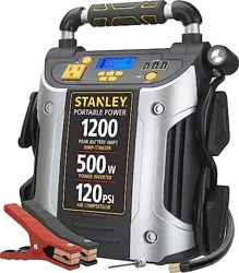
120
PORTABLE POWER STATION
INSTRUCTION MANUAL
FUENTE DE ENERGÍA PORTÁTIL
MANUAL DE INSTRUCCIÓN
SAVE THIS INSTRUCTION MANUAL FOR FUTURE REFERENCE.
CONSERVE ESTE MANUAL PARA FUTURAS CONSULTAS.
© 2021 Baccus Global LLC
Boca Raton, FL 33487
1-877-571-2391
J5CPD
English page 5
Español pagina 12
BC
• Asegúrese de haber seguido todos los pasos de la sección “120 tomacorrientes
de CA” con cuidado. Consulte las notas importantes incluidas en esa sección que
explican problemas y soluciones comunes.
• Asegúrese de que el aparato está alimentado no extrae más de 500 vatios.
• Refiera a las notas importantes incluidas en esa sección que explican problemas
comunes y soluciones.
• Compruebe que la unidad tiene una carga completa. Recargue la unidad en caso
de necesidad.
El puerto de la energía del USB no accionará la aplicación
• Asegúrese de que el botón de encendido/apagado del puerto de carga USB se ha
presionado para activar los puertos USB.
• Si existe una condición de falla en cualquiera de los puertos USB, el ícono de
falla en la pantalla LCD parpadeará. Consulte las notas importantes en la sección
“Puertos USB” para solucionar cualquier fallo.
• Asegúrese de que la extracción total de todos los dispositivos USB conectados a los
puertos USB izquierdos no exceda los 3.1A (5V).
• Algunos productos electrónicos de uso doméstico alimentados por USB no
funcionan con esta puerto de carga / potencia del USB. Compruebe el manual del
dispositivo electrónico correspondiente para confirmar que se puede utilizar con
este tipo de puerto de carga / potencia del USB.
• Compruebe que la unidad tiene una carga completa. Recargue la unidad en caso
de necesidad.
La luz de área LED no enciende
• Cerciórese de que el botón de encendido de la luz de área LED se ha presionado
para activar la luz de área LED.
• Compruebe que la unidad tiene una carga completa. Recargue la unidad en caso
de necesidad.
El compresor portátil no inflará
• Asegúrese de que la unidad no esté funcionando en el modo de inicio de salto.
• Asegúrese de que el botón de encendido del compresor se ha presionado para
activar el compresor.
• Asegúrese de que el conector de la boquilla Sure Fit
®
está firmemente atornillada
al vástago de válvula cuando se intenta inflar los neumáticos; o que el adaptador
de la boquilla se atornilla firmemente en el conector de la boquilla Sure Fit
®
y está
insertado correctamente en el elemento a ser inflado en todos los otros objetos
inflables.
• El compresor puede sobrecalentarse. Pulse el botón de encendido del compresor
para apagar el compresor. Reinicie después de un período de enfriamiento de 30
minutos aproximadamente.
• Compruebe que la unidad tiene una carga completa. Recargue la unidad en caso
de necesidad.
ACCESORIOS
Accesorios recomendados para uso con esta unidad puede ser disponibles a través
del fabricante. Si necesita ayuda con respecto a los accesorios, por favor póngase en
contacto con el fabricante al 1-877-571-2391.
El uso de cualquier accesorio no recomendado para el uso con esta unidad
podía ser peligroso.
INFORMACIÓN DE SERVICIO
Si usted necesita asesoramiento técnico, reparación, o partes genuinas del
fabricante, póngase en contacto con el fabricante al 1-877-571-2391.
UN AÑO DE GARANTÍA LIMITADA
El fabricante garantiza este producto contra defectos de materiales y mano de obra
durante un período de UN (1) AÑO a partir de la fecha de compra del producto
por el comprador usuario final (“Período de Garantía”). Si hay un defecto y una
reclamación válida se recibe dentro del período de garantía, el producto defectuoso
puede ser reemplazado o reparado en el las siguientes maneras: (1) Devuelva el
producto al fabricante para reparación o reemplazo, a opción del fabricante. La
prueba de compra puede ser requerida por el fabricante. (2) Devuelva el producto
a la tienda donde el producto fue comprado para un intercambio (siempre y
cuando se trate de un minorista participante). Devoluciones al minorista deben
hacerse dentro del plazo de póliza de devoluciones del minorista para intercambios
solamente (por lo general 30 a 90 días después de la fecha de compra). La prueba
de compra puede ser requerida por el minorista. Por favor consulte la póliza de
devoluciones del minorista sobre devoluciones que están fuera del plazo establecido
para intercambios.
Esta garantía no se aplica a los accesorios, bombillos, fusibles y baterías; defectos a
consecuencias de desgaste normal; accidentes; daños y perjuicios sufridos durante el
envío y manejo, alteraciones, reparaciones o uso no autorizado, negligencia, abuso,
y si no se siguen instrucciones para el cuidado y mantenimiento del producto.
Esta garantía le otorga al comprador usuario final, derechos legales específicos y
usted puede tener otros derechos que varían de estado a estado o de provincia a
provincia. Este producto no está diseñado para uso comercial.
Asegúrese de registrar su producto en https://www.baccusglobal.com/registration
para recibir información importante sobre el producto, promociones y ofertas
especiales, y más.
ESPECIFICACIONES
Amperios de impulso: 12V CC, 1200A pico batería,
600A instantánea
Tipo de batería: De plomo sin necesidad de mantenimiento,
sellada, 12V CC
Entrada de CA: 120V CA, 60Hz, 13W
Luz de área: 1 LED blanco
Puertos USB: 3.1A max., 5V CC
Tomacorriente de la CA: 120V CA, 60Hz, 500W continuo
Presión máxima del aparato
para compresor: 120 PSI
Sure Fit
®
es una marca registrada de los EE. UU. Propiedad de Baccus Global, LLC.
STANLEY
®
Y EL LOGOTIPO DE STANLEY
®
SON
MARCAS REGISTRADAS DE STANLEY BLACK + DECKER
INC. O DE UNA DE SUS FILIALES
Y SE UTILIZAN BAJO LICENCIA.
Importados por Baccus Global LLC,
621 NW 53rd St., Suite 450, Boca Raton, FL 33487
www.baccusglobal.com 1-877-571-2391
RD090921
2 3
FEATURES / CARACTERÍSTICAS
1
7 8 9
2
6
10
3 4 5
11 12
18
13
14 15
16 17
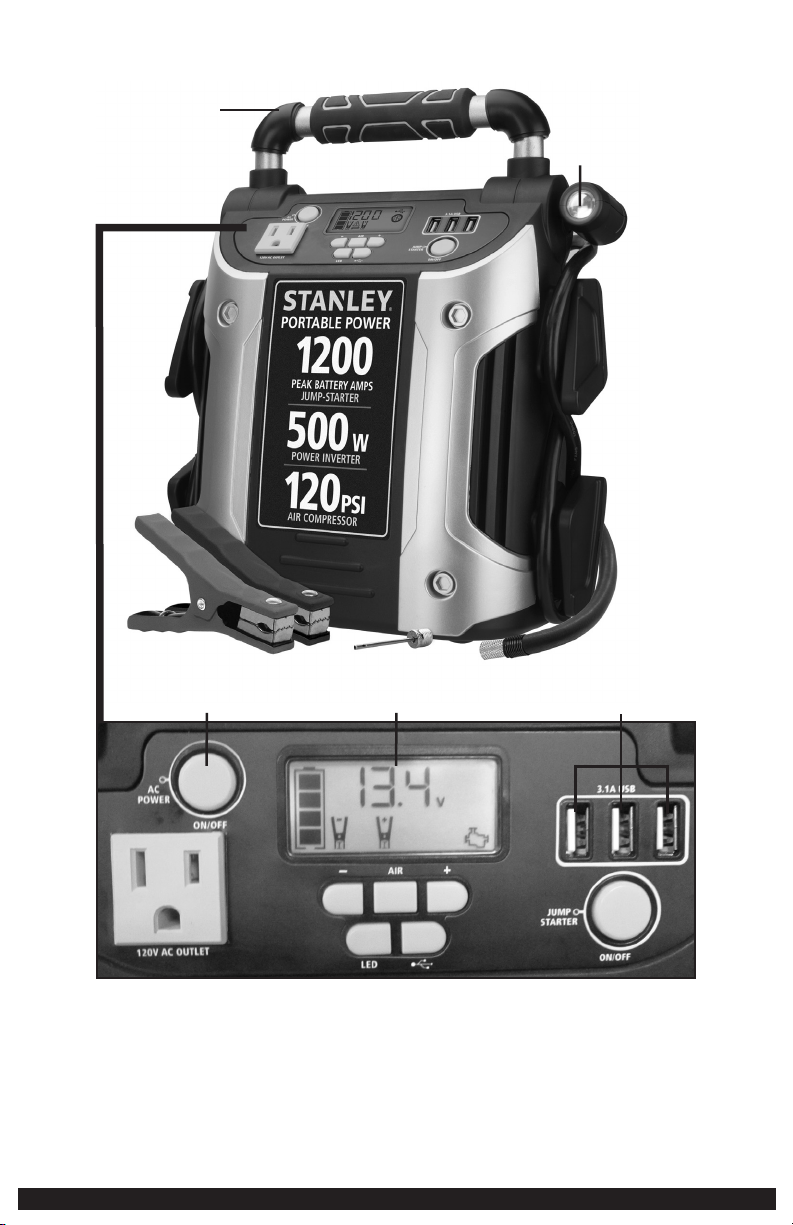
FEATURES
1. Rubber Grip Handle
2. Pivoting LED Area Light
3. AC Power Button
4. Backlit LCD Screen
5. USB Ports
6. Three-Prong 120 Volt AC Outlet
7. Decrease Compressor Pressure Control Button (–)
8. Compressor Power Button
9. Increase Compressor Pressure Control Button (+)
10. Jump Starter Power Button
11. Area Light Power Button
12. USB Power Button
13. Built-in 120 Volt AC Charger (under protective cover)
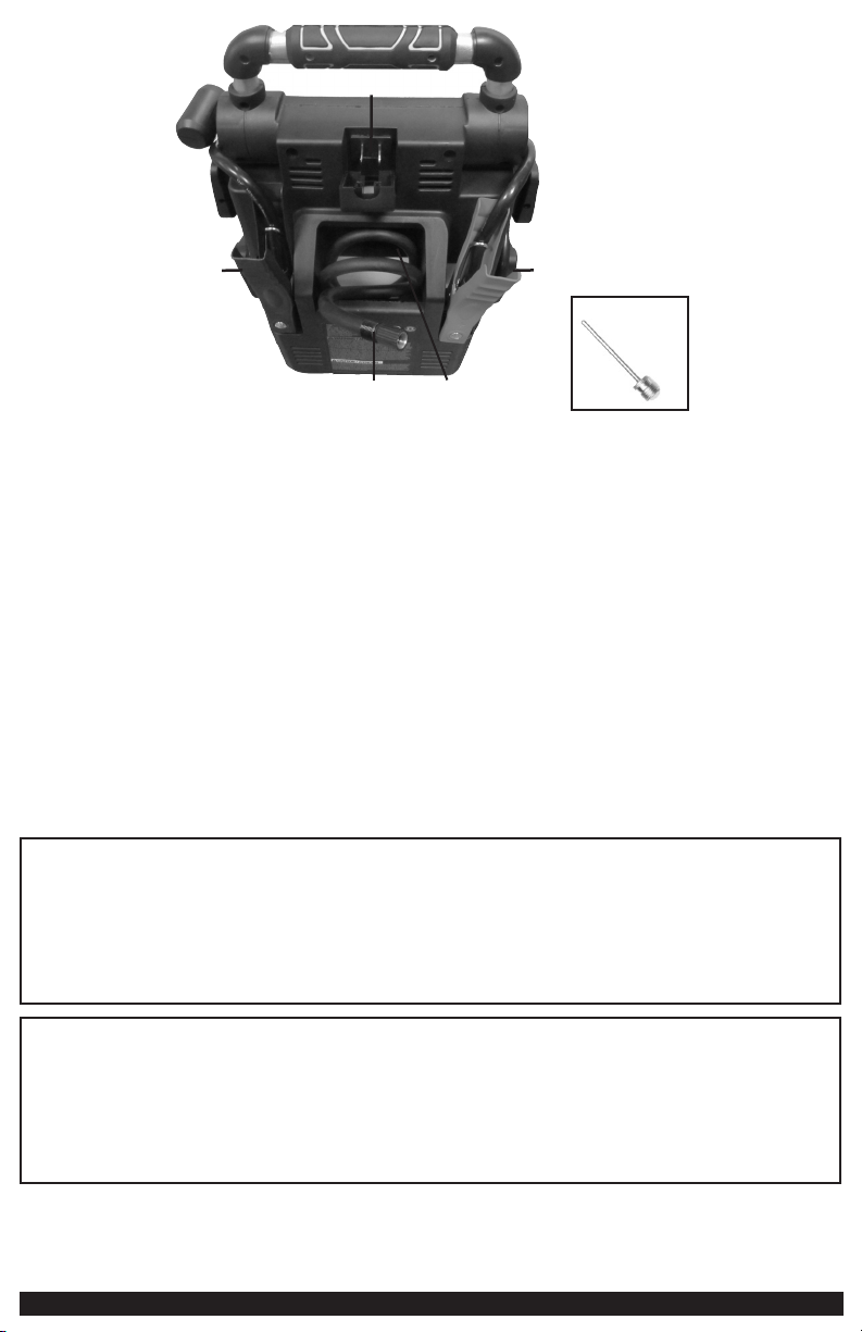
14. Negative (–) Black Clamp
15. Positive (+) Red Clamp
16. Air Hose and Sure Fit
®
Nozzle
17. Nozzle and Air Hose Storage
18. Nozzle Adapter
CARACTERÍSTICAS
1. Manija de goma
2. Lúz LED giratoria de área
3. Botón de alimentación de CA
4. Pantalla LCD retroiluminada
5. Puertos USB
6. Tomacorriente de tres patas de CA de 120 voltios
7. Botón de disminución de control de presión del compresor (–)
8. Botón de alimentación del compresor
9. Botón para aumentar la presión del compresor (+)
10. Botón de alimentación del puente auxiliar de arranque
11. Botón de encendido de la luz de área
12. Botón de alimentación USB
13. Cargador de CA de 120 voltios incorporado (bajo cubierta protectora)
14. Pinza negra del negativo (–)
15. Pinza roja del positivo (+)
16. Manguera e boquilla Sure Fit
®
17. Almacenamiento de boquilla y manguera de aire
18. Adaptador de boquilla
This device complies with part 15 of the FCC rules. Operation is subject to the following two conditions: (1) this device may not cause harmful interference, and (2) this device must accept any interference received, including
interference that may cause undesired operation.
This equipment has been tested and found to comply with the limits for a Class B digital device, pursuant to part 15 of the FCC Rules. These limits are designed to provide reasonable protection against harmful interference
in a residential installation. This equipment generates, uses and can radiate radio frequency energy and, if not installed and used in accordance with the instructions, may cause harmful interference to radio communications.
However, there is no guarantee that interference will not occur in a particular installation. If equipment does cause harmful interference to radio or television reception, which can be determined by turning the equipment off
and on, the user is encouraged to try to correct the interference by one or more of the following measures:
• Reorient or relocate the receiving antenna.
• Increase the separation between equipment and receiver.
• Connect the equipment into an outlet on a circuit different from that to which the receiver is connected.
• Consult the dealer or an experienced radio/TV technician for help.
Changes or modifications not approved by the party responsible for compliance could void user’s authority to operate the equipment.
Este dispositivo cumple con la parte 15 de las normas de la Comisión Federal de Comunicaciones de Estados Unidos (FCC). La operación está sujeta a las dos condiciones siguientes: (1) este dispositivo no puede causar interferencia
perjudicial y (2) este mecanismo debe aceptar cualquier interferencia recibida, incluida la in-terferencia que puede provocar una operación no deseada.
Este equipo ha sido probado y se encontró que cumple con los límites para dispositivo digital Clase B, según la parte 15 de las normas de la FCC. Estos límites están diseñados para brindar protección razonable contra
interferencia perjudicial en una instalación residencial. Este equipo genera, usa y puede irradiar energía en frecuencia de radio y, si no se instala y se usa de acuerdo con las instrucciones, puede provocar interferencia perjudicial
en las comunicaciones de radio. Sin embargo, no hay garantía de que la interferencia no ocurra en una instalación en particular. Si el equipo provoca interferencia perjudicial en la recepción de radio o televisión, lo que se puede
determinar al apagar y encender el equipo, el usuario debe tratar de corregir la interferencia mediante una o más de las siguientes medidas:
• Cambiar la orientación o la ubicación de la antena de recepción.
• Aumentar la separación entre el equipo y el receptor.
• Conectar el equipo a un tomacorriente sobre un circuito diferente de aquel al que está conectado el receptor.
• Consultar al vendedor o pedir la ayuda de un técnico en radio y televisión con experiencia.
Los cambios o las modificaciones no aprobados por el partido responsable de conformidad podían anular la autoridad del usuario para funcionar el equipo.
2 3
FEATURES / CARACTERÍSTICAS
1
7 8 9
2
6
10
3 4 5
11 12
18
13
14 15
16 17
FEATURES
1. Rubber Grip Handle
2. Pivoting LED Area Light
3. AC Power Button
4. Backlit LCD Screen
5. USB Ports
6. Three-Prong 120 Volt AC Outlet
7. Decrease Compressor Pressure Control Button (–)
8. Compressor Power Button
9. Increase Compressor Pressure Control Button (+)
10. Jump Starter Power Button
11. Area Light Power Button
12. USB Power Button
13. Built-in 120 Volt AC Charger (under protective cover)
14. Negative (–) Black Clamp
15. Positive (+) Red Clamp
16. Air Hose and Sure Fit
®
Nozzle
17. Nozzle and Air Hose Storage
18. Nozzle Adapter
CARACTERÍSTICAS
1. Manija de goma
2. Lúz LED giratoria de área
3. Botón de alimentación de CA
4. Pantalla LCD retroiluminada
5. Puertos USB
6. Tomacorriente de tres patas de CA de 120 voltios
7. Botón de disminución de control de presión del compresor (–)
8. Botón de alimentación del compresor
9. Botón para aumentar la presión del compresor (+)
10. Botón de alimentación del puente auxiliar de arranque
11. Botón de encendido de la luz de área
12. Botón de alimentación USB
13. Cargador de CA de 120 voltios incorporado (bajo cubierta protectora)
14. Pinza negra del negativo (–)
15. Pinza roja del positivo (+)
16. Manguera e boquilla Sure Fit
®
17. Almacenamiento de boquilla y manguera de aire
18. Adaptador de boquilla
This device complies with part 15 of the FCC rules. Operation is subject to the following two conditions: (1) this device may not cause harmful interference, and (2) this device must accept any interference received, including
interference that may cause undesired operation.
This equipment has been tested and found to comply with the limits for a Class B digital device, pursuant to part 15 of the FCC Rules. These limits are designed to provide reasonable protection against harmful interference
in a residential installation. This equipment generates, uses and can radiate radio frequency energy and, if not installed and used in accordance with the instructions, may cause harmful interference to radio communications.
However, there is no guarantee that interference will not occur in a particular installation. If equipment does cause harmful interference to radio or television reception, which can be determined by turning the equipment off
and on, the user is encouraged to try to correct the interference by one or more of the following measures:
• Reorient or relocate the receiving antenna.
• Increase the separation between equipment and receiver.
• Connect the equipment into an outlet on a circuit different from that to which the receiver is connected.
• Consult the dealer or an experienced radio/TV technician for help.
Changes or modifications not approved by the party responsible for compliance could void user’s authority to operate the equipment.
Este dispositivo cumple con la parte 15 de las normas de la Comisión Federal de Comunicaciones de Estados Unidos (FCC). La operación está sujeta a las dos condiciones siguientes: (1) este dispositivo no puede causar interferencia
perjudicial y (2) este mecanismo debe aceptar cualquier interferencia recibida, incluida la in-terferencia que puede provocar una operación no deseada.
Este equipo ha sido probado y se encontró que cumple con los límites para dispositivo digital Clase B, según la parte 15 de las normas de la FCC. Estos límites están diseñados para brindar protección razonable contra
interferencia perjudicial en una instalación residencial. Este equipo genera, usa y puede irradiar energía en frecuencia de radio y, si no se instala y se usa de acuerdo con las instrucciones, puede provocar interferencia perjudicial
en las comunicaciones de radio. Sin embargo, no hay garantía de que la interferencia no ocurra en una instalación en particular. Si el equipo provoca interferencia perjudicial en la recepción de radio o televisión, lo que se puede
determinar al apagar y encender el equipo, el usuario debe tratar de corregir la interferencia mediante una o más de las siguientes medidas:
• Cambiar la orientación o la ubicación de la antena de recepción.
• Aumentar la separación entre el equipo y el receptor.
• Conectar el equipo a un tomacorriente sobre un circuito diferente de aquel al que está conectado el receptor.
• Consultar al vendedor o pedir la ayuda de un técnico en radio y televisión con experiencia.
Los cambios o las modificaciones no aprobados por el partido responsable de conformidad podían anular la autoridad del usuario para funcionar el equipo.
54
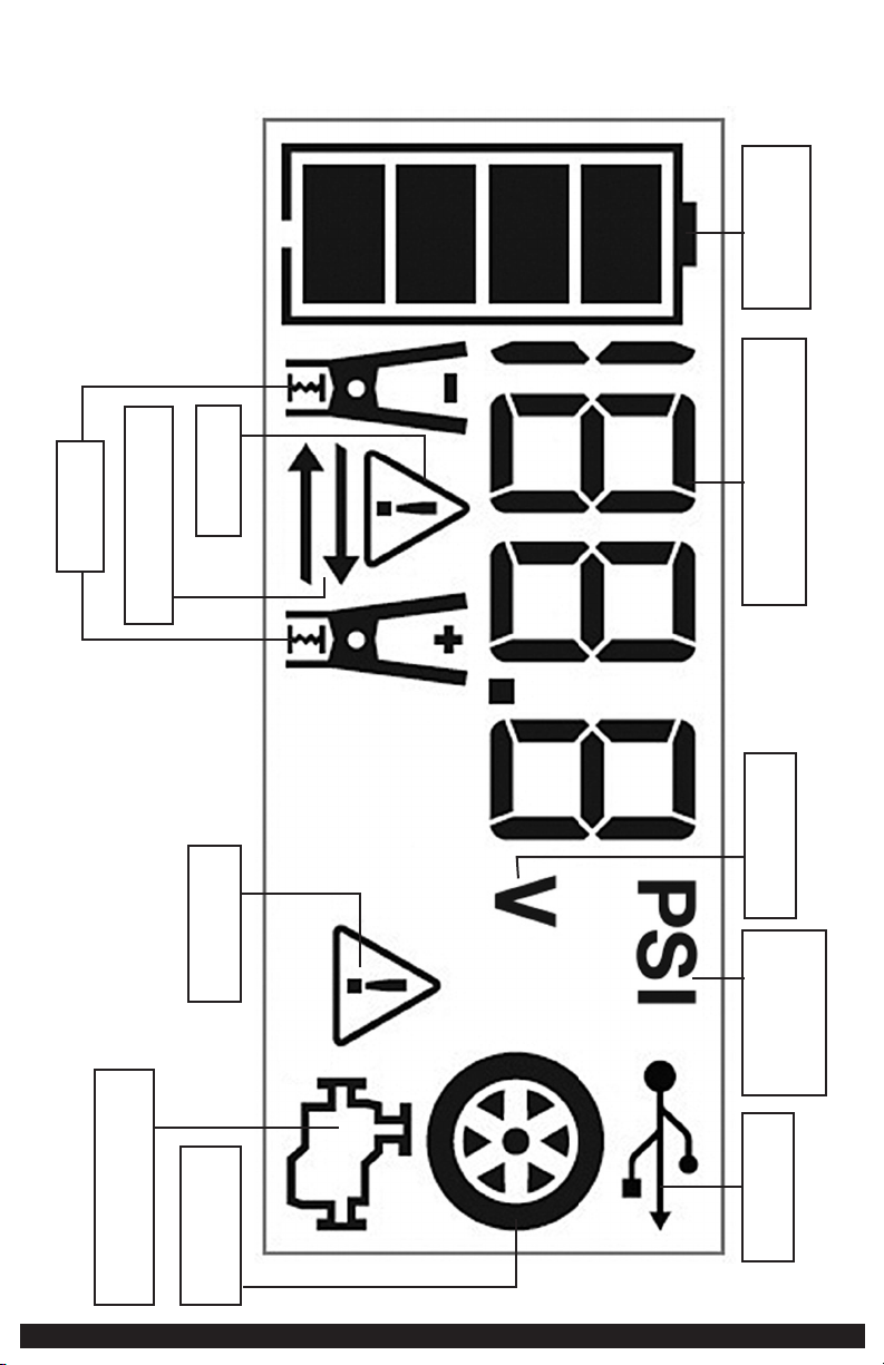
DIGITAL LCD SCREEN
PANTALLA DEL LCD DIGITAL
BATTERY STATUS ICON
ICONO DE ESTADO DE LA
BATERÍA
DIGITAL DISPLAY (VARIES BY FUNCTION)
INDICADOR DIGITAL (VARÍA DEPENDIENDO DE LA
FUNCIÓN)
ALARM ICON
ICONO DE ALARMA
REVERSE POLARITY ICONS
ICONOS DE POLARIDAD INVERSA
CLAMP ICONS
ICONOS DE PINZAS
COMPRESSOR PRESSURE
INDICATOR
INDICADOR DE PRESIÓN DEL
COMPRESOR
USB ICON
ICONO DE USB
COMPRESSOR ICON
ICONO DEL COMPRESOR
JUMP STARTER ICON
ICONO DEL PUENTE AUXILIAR DE ARRANQUE
FAULT ICON
ICONO DEL FALLO
VOLTAGE INDICATOR
INDICADOR DEL VOLTAJE
SAFETY GUIDELINES /
DEFINITIONS
DANGER: Indicates an imminently hazardous situation which, if not avoided,
will result in death or serious injury.
WARNING: Indicates a potentially hazardous situation which, if not avoided,
may result in death or serious injury.
CAUTION: Indicates a potentially hazardous situation which, if not avoided,
may result in minor or moderate injury.
Used without the word, indicates a safety related message.
NOTICE: Indicates a practice not related to personal injury which, if not avoided,
may result in property damage.
RISK OF UNSAFE OPERATION. When using tools or equipment, basic safety
precautions should always be followed to reduce the risk of personal injury.
Improper operation, maintenance or modification of tools or equipment could result
in serious injury and property damage. There are certain applications for which
tools and equipment are designed. Manufacturer strongly recommends that this
product NOT be modified and/or used for any application other than for which it
was designed. Read and understand all warnings and operating instructions before
using any tool or equipment.
READ ALL
INSTRUCTIONS
WARNING: Read and understand this instruction manual before using this
unit. Failure to follow all instructions listed below may result in electric shock, fire
and/or serious injury.
IMPORTANT SAFETY
INSTRUCTIONS
GENERAL SAFETY WARNINGS AND INSTRUCTIONS
• This unit was designed for household use only.
WARNING – Risk of fire, electric shock, burst hazard, or injury to persons or
property:
• Avoid dangerous environments. Don’t use appliances in damp or wet locations.
Don’t use appliances in the rain.
• Keep children away. All visitors should be kept at a distance from work area.
• Dress properly. Do not wear loose clothing or jewelry. They can be caught in
moving parts. Rubber gloves and substantial, non-skid footwear are recommended
when working outdoors. Wear protective hair covering to contain long hair.
• Store idle appliance indoors. When not in use, appliances should be stored indoors
in dry, and high or locked-up place – out of reach of children.
• Don’t abuse cord. Never carry appliance by cord or yank it to disconnect from
receptacle. Keep cord from heat, oil, and sharp edges.
• Disconnect appliances. Disconnect the appliance from the power supply when not
in use, before servicing, and when changing accessories.
• Ground Fault Circuit Interrupter (GFCI) protection should be provided on the
circuits or outlets to be used. Receptacles are available having built in GFCI
protection and may be used for this measure of safety.
• Use of accessories and attachments. The use of any accessory or attachment
not recommended for use with this appliance could be hazardous. Refer to the
accessory section of this manual for further details.
• Stay alert. Use common sense. Do not operate this equipment when you are tired
or impaired.
• Check for damaged parts. Any part that is damaged should be replaced by the
manufacturer before further use. Do not use tool if switch does not turn it on and
off. Contact the manufacturer at 1-877-571-2391 for more information.
• Do not operate this appliance near flammable liquids or in gaseous or explosive
atmospheres. Motors in these tools normally spark, and the sparks might ignite
fumes.
• Never submerge this unit in water; do not expose it to rain, snow or use when
wet.
• To reduce risk of electric shock, disconnect the unit from any power source before
attempting maintenance or cleaning. Turning off controls without disconnecting
will not reduce this risk.
• This equipment employs parts (switches, relays, etc.) that produce arcs or sparks.
Therefore, if used in a garage or enclosed area, the unit MUST be placed not less
than 18 inches above the floor.
• Do not insert foreign objects into the USB ports or the 120V AC outlet.
SPECIFIC SAFETY INSTRUCTIONS FOR CHARGING
THIS UNIT
• IMPORTANT: This unit is delivered in a partially charged state. Fully charge unit
with a household extension cord for a full 40 hours or until the battery status icon
shows 4 solid bars before using for the first time. You cannot overcharge the unit
using the AC charging method.
• To recharge this unit, use only the built-in AC charger.
• All functions should be turned off when the unit is charging or not in use. Make
sure all switches are in the OFF position before connection to a power source or
load.
EXTENSION CORDS:
WARNING: Use of improper extension cord could result in a risk of fire and
electric shock. When using an extension cord, make sure that the pins of the
extension cord are the same number, size and shape as those in the charger; and
be sure to use one heavy enough to carry the current your product will draw. An
undersized cord will cause a drop in line voltage resulting in loss of power and
overheating. The following table shows the correct size to use depending on cord
length and nameplate ampere rating. If in doubt, use the next heavier gauge. The
smaller the gauge number, the heavier the cord.
MINIMUM GAUGE FOR CORD SETS
Volts Total Length of Cord in Feet (meters)
120V 0-25 26-50 51-100 101-150
(0-7.6m) (7.6-15.2m) (15.2-30.4m) (30.4-45.7m)
240V 0-50 51-100 101-200 201-300
(0-15.2m) (15.2-30.4m) (30.4-60.9m) (60.9-91.4m)
Ampere Rating Extension Cord Length
More Not more
0’-25’ 26’-50’ 51’-100’ 101’ -150’
Than Than American Wire Gauge (AWG)
0 - 6 18 16 16 14
6 - 10 18 16 14 12
10 - 12 16 16 14 12
12 - 16 14 12 Not Recommended
When an extension cord is used, make sure that:
– the pins of extension cord are the same number, size and shape as those in
the charger,
– the extension cord is properly wired and in good electrical condition,
– the wire size is large enough for the AC rating of the charger.
CAUTION – To reduce the risk of injury or property damage:
Pull the extension cord by the plug rather than the cord when disconnecting from
the built-in 120 volt AC charger or the AC outlet.
SPECIFIC SAFETY INSTRUCTIONS FOR JUMP STARTERS
WARNING: Burst hazard:
Do not use the unit for charging dry-cell batteries that are commonly used with
home appliances. These batteries may burst and cause injury to persons and
damage property. Use the unit for charging/boosting a lead-acid battery only. It is
not intended to supply power to a low-voltage electrical system other than in a
starter-motor application.
• Use of an attachment not supplied, recommended or sold by manufacturer
specifically for use with this unit may result in a risk of electrical shock and injury
to persons.
WARNING: Risk of explosive gases:
• Working in the vicinity of a lead acid battery is dangerous. Batteries generate
explosive gases during normal battery operation. For this reason, it is of the
utmost importance that each time before using the jump-starter you read this
manual and follow instructions exactly.
• To reduce the risk of battery explosion, follow these instructions and those
published by the battery manufacturer and manufacturer of any equipment you
intend to use in the vicinity of the battery. Review cautionary markings on these
products and on the engine.
CAUTION – To reduce the risk of injury or property damage:
• NEVER ATTEMPT TO JUMP-START OR CHARGE A FROZEN BATTERY.

54
DIGITAL LCD SCREEN
PANTALLA DEL LCD DIGITAL
BATTERY STATUS ICON
ICONO DE ESTADO DE LA
BATERÍA
DIGITAL DISPLAY (VARIES BY FUNCTION)
INDICADOR DIGITAL (VARÍA DEPENDIENDO DE LA
FUNCIÓN)
ALARM ICON
ICONO DE ALARMA
REVERSE POLARITY ICONS
ICONOS DE POLARIDAD INVERSA
CLAMP ICONS
ICONOS DE PINZAS
COMPRESSOR PRESSURE
INDICATOR
INDICADOR DE PRESIÓN DEL
COMPRESOR
USB ICON
ICONO DE USB
COMPRESSOR ICON
ICONO DEL COMPRESOR
JUMP STARTER ICON
ICONO DEL PUENTE AUXILIAR DE ARRANQUE
FAULT ICON
ICONO DEL FALLO
VOLTAGE INDICATOR
INDICADOR DEL VOLTAJE
SAFETY GUIDELINES /
DEFINITIONS
DANGER: Indicates an imminently hazardous situation which, if not avoided,
will result in death or serious injury.
WARNING: Indicates a potentially hazardous situation which, if not avoided,
may result in death or serious injury.
CAUTION: Indicates a potentially hazardous situation which, if not avoided,
may result in minor or moderate injury.
Used without the word, indicates a safety related message.
NOTICE: Indicates a practice not related to personal injury which, if not avoided,
may result in property damage.
RISK OF UNSAFE OPERATION. When using tools or equipment, basic safety
precautions should always be followed to reduce the risk of personal injury.
Improper operation, maintenance or modification of tools or equipment could result
in serious injury and property damage. There are certain applications for which
tools and equipment are designed. Manufacturer strongly recommends that this
product NOT be modified and/or used for any application other than for which it
was designed. Read and understand all warnings and operating instructions before
using any tool or equipment.
READ ALL
INSTRUCTIONS
WARNING: Read and understand this instruction manual before using this
unit. Failure to follow all instructions listed below may result in electric shock, fire
and/or serious injury.
IMPORTANT SAFETY
INSTRUCTIONS
GENERAL SAFETY WARNINGS AND INSTRUCTIONS
• This unit was designed for household use only.
WARNING – Risk of fire, electric shock, burst hazard, or injury to persons or
property:
• Avoid dangerous environments. Don’t use appliances in damp or wet locations.
Don’t use appliances in the rain.
• Keep children away. All visitors should be kept at a distance from work area.
• Dress properly. Do not wear loose clothing or jewelry. They can be caught in
moving parts. Rubber gloves and substantial, non-skid footwear are recommended
when working outdoors. Wear protective hair covering to contain long hair.
• Store idle appliance indoors. When not in use, appliances should be stored indoors
in dry, and high or locked-up place – out of reach of children.
• Don’t abuse cord. Never carry appliance by cord or yank it to disconnect from
receptacle. Keep cord from heat, oil, and sharp edges.
• Disconnect appliances. Disconnect the appliance from the power supply when not
in use, before servicing, and when changing accessories.
• Ground Fault Circuit Interrupter (GFCI) protection should be provided on the
circuits or outlets to be used. Receptacles are available having built in GFCI
protection and may be used for this measure of safety.
• Use of accessories and attachments. The use of any accessory or attachment
not recommended for use with this appliance could be hazardous. Refer to the
accessory section of this manual for further details.
• Stay alert. Use common sense. Do not operate this equipment when you are tired
or impaired.
• Check for damaged parts. Any part that is damaged should be replaced by the
manufacturer before further use. Do not use tool if switch does not turn it on and
off. Contact the manufacturer at 1-877-571-2391 for more information.
• Do not operate this appliance near flammable liquids or in gaseous or explosive
atmospheres. Motors in these tools normally spark, and the sparks might ignite
fumes.
• Never submerge this unit in water; do not expose it to rain, snow or use when
wet.
• To reduce risk of electric shock, disconnect the unit from any power source before
attempting maintenance or cleaning. Turning off controls without disconnecting
will not reduce this risk.
• This equipment employs parts (switches, relays, etc.) that produce arcs or sparks.
Therefore, if used in a garage or enclosed area, the unit MUST be placed not less
than 18 inches above the floor.
• Do not insert foreign objects into the USB ports or the 120V AC outlet.
SPECIFIC SAFETY INSTRUCTIONS FOR CHARGING
THIS UNIT
• IMPORTANT: This unit is delivered in a partially charged state. Fully charge unit
with a household extension cord for a full 40 hours or until the battery status icon
shows 4 solid bars before using for the first time. You cannot overcharge the unit
using the AC charging method.
• To recharge this unit, use only the built-in AC charger.
• All functions should be turned off when the unit is charging or not in use. Make
sure all switches are in the OFF position before connection to a power source or
load.
EXTENSION CORDS:
WARNING: Use of improper extension cord could result in a risk of fire and
electric shock. When using an extension cord, make sure that the pins of the
extension cord are the same number, size and shape as those in the charger; and
be sure to use one heavy enough to carry the current your product will draw. An
undersized cord will cause a drop in line voltage resulting in loss of power and
overheating. The following table shows the correct size to use depending on cord
length and nameplate ampere rating. If in doubt, use the next heavier gauge. The
smaller the gauge number, the heavier the cord.
MINIMUM GAUGE FOR CORD SETS
Volts Total Length of Cord in Feet (meters)
120V 0-25 26-50 51-100 101-150
(0-7.6m) (7.6-15.2m) (15.2-30.4m) (30.4-45.7m)
240V 0-50 51-100 101-200 201-300
(0-15.2m) (15.2-30.4m) (30.4-60.9m) (60.9-91.4m)
Ampere Rating Extension Cord Length
More Not more
0’-25’ 26’-50’ 51’-100’ 101’ -150’
Than Than American Wire Gauge (AWG)
0 - 6 18 16 16 14
6 - 10 18 16 14 12
10 - 12 16 16 14 12
12 - 16 14 12 Not Recommended
When an extension cord is used, make sure that:
– the pins of extension cord are the same number, size and shape as those in
the charger,
– the extension cord is properly wired and in good electrical condition,
– the wire size is large enough for the AC rating of the charger.
CAUTION – To reduce the risk of injury or property damage:
Pull the extension cord by the plug rather than the cord when disconnecting from
the built-in 120 volt AC charger or the AC outlet.
SPECIFIC SAFETY INSTRUCTIONS FOR JUMP STARTERS
WARNING: Burst hazard:
Do not use the unit for charging dry-cell batteries that are commonly used with
home appliances. These batteries may burst and cause injury to persons and
damage property. Use the unit for charging/boosting a lead-acid battery only. It is
not intended to supply power to a low-voltage electrical system other than in a
starter-motor application.
• Use of an attachment not supplied, recommended or sold by manufacturer
specifically for use with this unit may result in a risk of electrical shock and injury
to persons.
WARNING: Risk of explosive gases:
• Working in the vicinity of a lead acid battery is dangerous. Batteries generate
explosive gases during normal battery operation. For this reason, it is of the
utmost importance that each time before using the jump-starter you read this
manual and follow instructions exactly.
• To reduce the risk of battery explosion, follow these instructions and those
published by the battery manufacturer and manufacturer of any equipment you
intend to use in the vicinity of the battery. Review cautionary markings on these
products and on the engine.
CAUTION – To reduce the risk of injury or property damage:
• NEVER ATTEMPT TO JUMP-START OR CHARGE A FROZEN BATTERY.

6 7
• Vehicles that have on-board computerized systems may be damaged if vehicle
battery is jump-started. Before jump-starting, read the vehicle’s owner’s manual to
confirm that external-starting assistance is suitable.
• Never smoke or allow a spark or flame in vicinity of vehicle battery, engine or
power station
• Stay clear of fan blades, belts, pulleys, and other parts that can cause injury to
persons.
• Be extra careful to avoid dropping a metal tool onto the battery. It might spark or
short-circuit the battery or another electrical part and could cause an explosion.
• Jump-start procedures should only be performed in a safe, dry, well-ventilated area.
• Always store battery clamps when not in use. Never touch battery clamps together.
This can cause dangerous sparks, power arcing and/or explosion.
• When using this unit close to the vehicle’s battery and engine, stand the unit on a
flat, stable surface, and be sure to keep all clamps, cords, clothing and body parts
away from moving vehicle parts.
• Never allow red and black clamps to touch each other or another common metal
conductor – this could cause damage to the unit and/or create a sparking/explosion
hazard.
– For negative-grounded systems, connect the positive (red) clamp to the positive
ungrounded battery post and the negative (black) clamp to the vehicle chassis
or engine block away from the battery. Do not connect the clamp to the
carburetor, fuel lines or sheet-metal body parts. Connect to a heavy gauge
metal part of the frame or engine block.
– For positive-grounded systems, connect the negative (black) clamp to the
negative ungrounded battery post and the positive (red) clamp to the vehicle
chassis or engine block away from the battery. Do not connect the clamp to
the carburetor, fuel lines or sheet-metal body parts. Connect to a heavy gauge
metal part of the frame or engine block.
• If the clamps are connected incorrectly with regard to polarity, the backlit LCD
screen will display the Battery Status Icon, Battery Voltage Indicator, and the Clamp
Icons. The Alarm Icon, the “+” and ”–” signs and the Reverse Polarity Icons will
flash and the unit will sound a continuous alarm until the clamps are disconnected.
Disconnect the clamps and reconnect to battery with correct polarity.
• Always disconnect the negative (black) jumper cable first, followed by the positive
(red) jumper cable, except for positive grounded systems.
• Do not expose battery to fire or intense heat since it may explode. Before
disposing of the battery, protect exposed terminals with heavy-duty electrical tape
to prevent shorting (shorting can result in injury or fire).
• Place this unit as far away from the battery as cables permit.
• Never allow battery acid to come in contact with this unit.
• Do not operate this unit in a closed area or restrict ventilation in any way.
• This system is designed to be used only on vehicles with a 12 volt DC battery
system. Do not connect to a 6 volt or 24 volt battery system.
• This system is not designed to be used as a replacement for a vehicular battery. Do
not attempt to operate a vehicle that does not have a battery installed.
• Excessive engine cranking can damage a vehicle’s starter motor. If the engine
fails to start after the recommended number of attempts, discontinue jump-start
procedures and look for other problems that may need to be corrected.
• Do not use this jump starter on a watercraft. It is not qualified for marine
applications.
• Although this unit contains a non-spillable battery, it is recommended that unit be
kept upright during storage, use and recharging. To avoid possible damage that
may shorten the unit’s working life, protect it from direct sunlight, direct heat and/
or moisture.
SPECIFIC SAFETY INSTRUCTIONS FOR INVERTERS
WARNING – To reduce the risk of electric shock:
• Do not connect to AC distribution wiring.
• Do not make any electrical connections or disconnections in areas designated as
IGNITION PROTECTED. This inverter is NOT approved for ignition protected areas.
• Never immerse the unit in water or any other liquid, or use when wet.
• Do not insert foreign objects into the unit’s AC outlets.
WARNING – To reduce the risk of fire:
• Do not operate near flammable materials, fumes or gases.
• Do not expose to extreme heat or flames.
CAUTION – To reduce the risk of injury or property damage:
• Disconnect appliance plug from inverter outlet before attempting any repairs to
the appliance.
• When an appliance plugged into this unit is used outdoors, use only extension
cords intended for use outdoors and so marked.
• Do not attempt to connect the inverter while operating your vehicle. Not paying
attention to the road may result in a serious accident.
• Always use the inverter where there is adequate ventilation.
• Always turn the inverter off when not in use.
• Keep in mind that this inverter will not operate high wattage appliances or
equipment that produce heat, such as hair dryers, microwave ovens and toasters.
• Do not use this inverter with medical devices. It is not tested for medical
applications.
• Some laptop computers may not operate with this inverter.
• Operate inverter only as described in this Instruction Manual.
CAUTION – Rechargeable devices:
• Certain rechargeable devices are designed to be charged by plugging them directly
into an AC receptacle. These devices may damage the inverter or the charging
circuit.
• When using a rechargeable device, monitor its temperature for the initial ten
minutes of use to determine if it produces excessive heat.
• If excessive heat is produced, this indicates the device should not be used with
this inverter.
• This problem does not occur with most of the battery-operated equipment. Most
of these devices use a separate charger or transformer that is plugged into an AC
receptacle.
• The inverter is capable of running most chargers and transformers.
SPECIFIC SAFETY INSTRUCTIONS FOR THE USB PORTS
• Do not insert foreign objects into the USB Ports.
• Do not attach USB hubs or more than one personal electronic device to each USB
Port.
• Do not use this unit to operate appliances that require more than 3.1A (5V) to
operate from each of the USB Ports.
• Some household USB-powered electronics will not operate with this unit.
SPECIFIC SAFETY INSTRUCTIONS FOR COMPRESSORS
CAUTION – To reduce the risk of injury or property damage:
• Never leave the compressor unattended while in use.
• Do not operate compressor continuously for longer than approximately 10
minutes, depending on ambient temperatures, as it may overheat. This could
damage the compressor. Follow the instructions in the “Portable Compressor”
section.
WARNING – Burst hazard: Bursting articles can cause serious injury.
• Carefully follow instructions on articles to be inflated.
• Never exceed the recommended pressure listed in instructions on articles to be
inflated. If no pressure is given, contact article manufacturer before inflating.
• Monitor the pressure at all times on the LCD screen.
PERSONAL SAFETY
When working with lead acid batteries, always make sure immediate assistance is
available in case of accident or emergency.
Remove personal metal items such as rings, bracelets, necklaces and watches when
working with a lead acid battery. A lead acid battery can produce a short circuit
current high enough to weld a ring, or similar metal object, to skin, causing a
severe burn.
Do not wear vinyl clothing when jump-starting a vehicle. Friction can cause
dangerous static-electrical sparks.
Always have protective eyewear when using this product: contact with battery acid
may cause blindness and/or severe burns. Be aware of first aid procedures in case of
accidental contact with battery acid.
Have plenty of fresh water and soap nearby in case battery acid contacts skin.
• SKIN: If battery acid comes in contact with skin, rinse immediately with water,
then wash thoroughly with soap and water. If redness, pain, or irritation occurs,
seek immediate medical attention.
• EYES: If battery acid comes in contact with eyes, flush eyes immediately, for a
minimum of 15 minutes and seek immediate medical attention.
• LCD LIQUID CRYSTAL DISPLAY: If liquid crystal comes in contact with your
skin: Wash area off completely with plenty of water. Remove contaminated
clothing. If liquid crystal gets into your eye: Flush the affected eye with clean
water and then seek medical attention. If liquid crystal is swallowed: Flush
your mouth thoroughly with water. Drink large quantities of water and induce
vomiting. Then seek medical attention.
SAVE THESE
INSTRUCTIONS
INTRODUCTION
Congratulations on purchasing your new Portable Power Station. Read this
Instruction Manual and follow the instructions carefully before using this unit.
OVERVIEW
Common Actions and Unit Responses
The following actions turn the unit on and activate the LCD screen:
Press the LED Area Light
Power Button. (Refer to
the "LED Area Light"
section.)
A beep will sound and the Area Light will turn on.
The backlight will turn on for 10 seconds (only).
The LCD screen will continue to display the Battery
Status Icon and Battery Voltage Indicator. The unit
remains on until the LED Area Light Power Button
is pressed again to turn it off.
Press the AC Power
Button. (Refer to the
“120V AC Power Outlet”
section.)
A beep will sound and the LCD screen will display
the Battery Status Icon and the Digital Display
shows “AC”, indicating the AC outlet is ready
to use. The unit remains on until the AC Power
Button is pressed again to turn it off.
Press the USB Power
Button. (Refer to the
"USB Ports" section.)
A beep will sound and the USB Ports will turn on.
The backlight will turn on for 10 seconds (only).
The LCD screen will display the Battery Status
Icon, Battery Voltage Indicator, and the USB Icon;
indicating the three USB Ports are active. The unit
remains on until the USB Power Button is pressed
again to turn it off.
Press the Compressor
Power Button. (Refer
to the "Portable
Compressor" section.)
A beep will sound and the backlit LCD screen will
display the Battery Status Icon, "XXX" PSI and the
Compressor Icon. If no further actions are taken
after 1 minute, the unit will display the Battery
Status Icon and Battery Voltage Indicator for 10
seconds before automatically turning off.
Whenever the clamps
are properly connected
to a battery (refer to
the "Jump Starter"
section) …
… a beep will sound and the backlit LCD screen
will display the Battery Status Icon, Battery
Voltage Indicator, the Clamp Icons, and the “+”
and ”–” signs. The unit remains on until the
clamps are disconnected from the battery.
If the Jump Starter
Power Button has been
pressed to turn the
jump starter on and the
clamps are not connected
to a battery (refer to the
"Jump Starter" section.)
The backlit LCD screen will display the Battery
Status Icon and the Battery Voltage Indicator for
10 seconds before automatic shut down.
If the clamp connections
to the battery’s positive
and negative terminals
are reversed (refer to
the "Jump Starter"
section) …
… the backlit LCD screen will display the Battery
Status Icon, Battery Voltage Indicator, and the
Clamp Icons. The Alarm Icon, the “+” and ”–”
signs and the Reverse Polarity Icons will flash and
the unit will sound a warning continuously until
the clamps are disconnected from the battery.
If the red and black
clamps touch each other
(refer to the “Jump
Starter” section) …
… the backlit LCD screen will display the Battery
Status Icon and Battery Voltage Indicator. The
Clamp Icons, “+” and ”–” signs and the Alarm
Icon will flash. The unit will sound a two-second
warning every ten seconds continuously until the
clamps are separated.
When the unit is
charging
or recharging using the
built-in 120 Volt AC
Charger (refer to the
"Charging/Recharging"
section) …
… the backlight will turn on for 10 seconds (only).
The LCD screen will continue to display the Battery
Status Icon and Battery Voltage Indicator. The bars
on the Battery Status Icon will change from empty
to solid (bottom to top) repeatedly.
Note: The unit will automatically power off once ALL the functions are turned off.
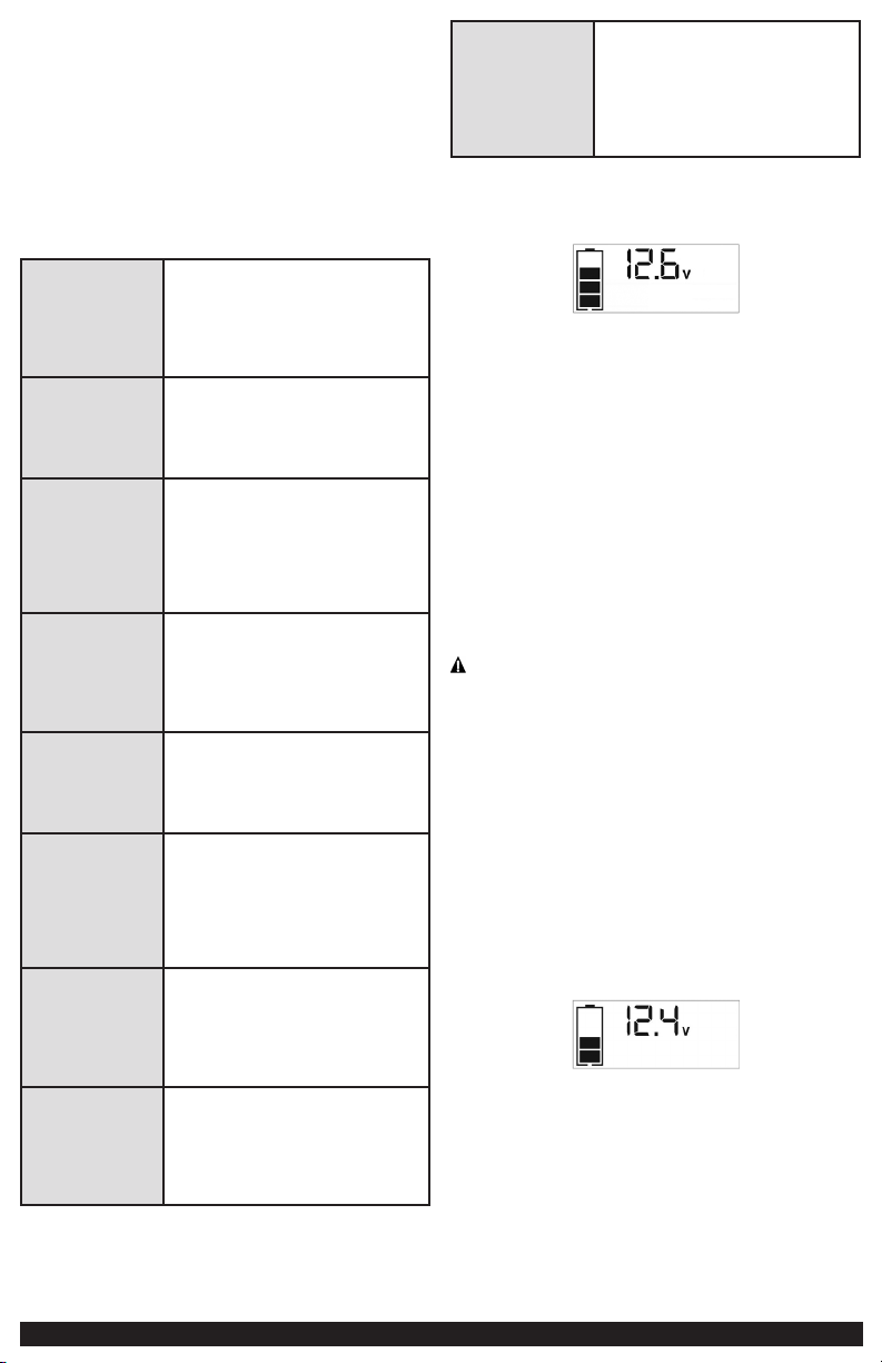
VIEWING BATTERY STATUS
The Battery Status Icon and Battery Voltage Indicator indicate the battery charge
level as follows.
• If the battery charge level is at full capacity, four solid bars will display.
• If the battery is partially charged, two or three solid bars will display.
• If the battery is nearly empty, one solid bar will display. The unit should be
charged at this time.
• If the battery is completely empty, four blank bars will display. The unit MUST be
charged at this time or the unit’s built-in low voltage protection will activate. The
empty Battery Status Icon will flash for a short period of time before automatic
shut down. The unit will not operate until the battery is recharged.
CHARGING/RECHARGING
This unit is delivered in a partially charged state – you must fully charge it before
using it for the first time. Initial AC charge should be for 40 hours or until the Battery
Status Icon shows 4 solid bars.
Lead-acid batteries require routine maintenance to ensure a full charge and long
battery life. All batteries lose energy from self-discharge over time and more
rapidly at higher temperatures. Therefore, batteries need periodic charging to
replace energy lost through self-discharge. When the unit is not in frequent use,
manufacturer recommends the battery should be recharged at least every 30 days
and after each use.
CAUTION – RISK OF PROPERTY DAMAGE: Failure to keep the battery charged
will cause permanent damage and result in poor jump starting performance.
IMPORTANT NOTES:
• Recharging the battery after each use will prolong battery life; frequent heavy
discharges between recharges and/or overcharging will reduce battery life.
• Make sure all other unit functions are turned off during recharging, as this can
slow the recharging process.
• If you know the unit is discharged, but the battery icon displays four solid bars as
if the unit is fully charged when connected to a charging power source, this may
be due to the internal battery having high impedance. The manufacturer suggests
leaving the unit charging for a period of 40 hours using the built-in AC charger
before use.
Charging/Recharging Using the Built-In 120 Volt AC Charger
and AC Extension Cord (not included)
1. Lift the protective cover of the built-in 120 Volt AC Charger (refer to the
“Features section to locate). Connect an extension cord to the unit. Plug the
other end of the cord into a standard 120-volt AC wall outlet. When the unit
is properly connected to an AC power source, the LCD screen will display the
following:
The bars on the Battery Status Icon represent the charge level of the unit’s
internal battery. The bars on the Battery Status Icon will change from empty to
solid (bottom to top) repeatedly to indicate the unit is charging. The backlight
will turn on for 10 seconds (only).
2. Charge for approximately 40 hours or until the Battery Status Icon shows 4
solid bars.
3. When charging is complete, unplug the AC extension cord from the AC outlet
and then disconnect it from the unit.
6 7
• Vehicles that have on-board computerized systems may be damaged if vehicle
battery is jump-started. Before jump-starting, read the vehicle’s owner’s manual to
confirm that external-starting assistance is suitable.
• Never smoke or allow a spark or flame in vicinity of vehicle battery, engine or
power station
• Stay clear of fan blades, belts, pulleys, and other parts that can cause injury to
persons.
• Be extra careful to avoid dropping a metal tool onto the battery. It might spark or
short-circuit the battery or another electrical part and could cause an explosion.
• Jump-start procedures should only be performed in a safe, dry, well-ventilated area.
• Always store battery clamps when not in use. Never touch battery clamps together.
This can cause dangerous sparks, power arcing and/or explosion.
• When using this unit close to the vehicle’s battery and engine, stand the unit on a
flat, stable surface, and be sure to keep all clamps, cords, clothing and body parts
away from moving vehicle parts.
• Never allow red and black clamps to touch each other or another common metal
conductor – this could cause damage to the unit and/or create a sparking/explosion
hazard.
– For negative-grounded systems, connect the positive (red) clamp to the positive
ungrounded battery post and the negative (black) clamp to the vehicle chassis
or engine block away from the battery. Do not connect the clamp to the
carburetor, fuel lines or sheet-metal body parts. Connect to a heavy gauge
metal part of the frame or engine block.
– For positive-grounded systems, connect the negative (black) clamp to the
negative ungrounded battery post and the positive (red) clamp to the vehicle
chassis or engine block away from the battery. Do not connect the clamp to
the carburetor, fuel lines or sheet-metal body parts. Connect to a heavy gauge
metal part of the frame or engine block.
• If the clamps are connected incorrectly with regard to polarity, the backlit LCD
screen will display the Battery Status Icon, Battery Voltage Indicator, and the Clamp
Icons. The Alarm Icon, the “+” and ”–” signs and the Reverse Polarity Icons will
flash and the unit will sound a continuous alarm until the clamps are disconnected.
Disconnect the clamps and reconnect to battery with correct polarity.
• Always disconnect the negative (black) jumper cable first, followed by the positive
(red) jumper cable, except for positive grounded systems.
• Do not expose battery to fire or intense heat since it may explode. Before
disposing of the battery, protect exposed terminals with heavy-duty electrical tape
to prevent shorting (shorting can result in injury or fire).
• Place this unit as far away from the battery as cables permit.
• Never allow battery acid to come in contact with this unit.
• Do not operate this unit in a closed area or restrict ventilation in any way.
• This system is designed to be used only on vehicles with a 12 volt DC battery
system. Do not connect to a 6 volt or 24 volt battery system.
• This system is not designed to be used as a replacement for a vehicular battery. Do
not attempt to operate a vehicle that does not have a battery installed.
• Excessive engine cranking can damage a vehicle’s starter motor. If the engine
fails to start after the recommended number of attempts, discontinue jump-start
procedures and look for other problems that may need to be corrected.
• Do not use this jump starter on a watercraft. It is not qualified for marine
applications.
• Although this unit contains a non-spillable battery, it is recommended that unit be
kept upright during storage, use and recharging. To avoid possible damage that
may shorten the unit’s working life, protect it from direct sunlight, direct heat and/
or moisture.
SPECIFIC SAFETY INSTRUCTIONS FOR INVERTERS
WARNING – To reduce the risk of electric shock:
• Do not connect to AC distribution wiring.
• Do not make any electrical connections or disconnections in areas designated as
IGNITION PROTECTED. This inverter is NOT approved for ignition protected areas.
• Never immerse the unit in water or any other liquid, or use when wet.
• Do not insert foreign objects into the unit’s AC outlets.
WARNING – To reduce the risk of fire:
• Do not operate near flammable materials, fumes or gases.
• Do not expose to extreme heat or flames.
CAUTION – To reduce the risk of injury or property damage:
• Disconnect appliance plug from inverter outlet before attempting any repairs to
the appliance.
• When an appliance plugged into this unit is used outdoors, use only extension
cords intended for use outdoors and so marked.
• Do not attempt to connect the inverter while operating your vehicle. Not paying
attention to the road may result in a serious accident.
• Always use the inverter where there is adequate ventilation.
• Always turn the inverter off when not in use.
• Keep in mind that this inverter will not operate high wattage appliances or
equipment that produce heat, such as hair dryers, microwave ovens and toasters.
• Do not use this inverter with medical devices. It is not tested for medical
applications.
• Some laptop computers may not operate with this inverter.
• Operate inverter only as described in this Instruction Manual.
CAUTION – Rechargeable devices:
• Certain rechargeable devices are designed to be charged by plugging them directly
into an AC receptacle. These devices may damage the inverter or the charging
circuit.
• When using a rechargeable device, monitor its temperature for the initial ten
minutes of use to determine if it produces excessive heat.
• If excessive heat is produced, this indicates the device should not be used with
this inverter.
• This problem does not occur with most of the battery-operated equipment. Most
of these devices use a separate charger or transformer that is plugged into an AC
receptacle.
• The inverter is capable of running most chargers and transformers.
SPECIFIC SAFETY INSTRUCTIONS FOR THE USB PORTS
• Do not insert foreign objects into the USB Ports.
• Do not attach USB hubs or more than one personal electronic device to each USB
Port.
• Do not use this unit to operate appliances that require more than 3.1A (5V) to
operate from each of the USB Ports.
• Some household USB-powered electronics will not operate with this unit.
SPECIFIC SAFETY INSTRUCTIONS FOR COMPRESSORS
CAUTION – To reduce the risk of injury or property damage:
• Never leave the compressor unattended while in use.
• Do not operate compressor continuously for longer than approximately 10
minutes, depending on ambient temperatures, as it may overheat. This could
damage the compressor. Follow the instructions in the “Portable Compressor”
section.
WARNING – Burst hazard: Bursting articles can cause serious injury.
• Carefully follow instructions on articles to be inflated.
• Never exceed the recommended pressure listed in instructions on articles to be
inflated. If no pressure is given, contact article manufacturer before inflating.
• Monitor the pressure at all times on the LCD screen.
PERSONAL SAFETY
When working with lead acid batteries, always make sure immediate assistance is
available in case of accident or emergency.
Remove personal metal items such as rings, bracelets, necklaces and watches when
working with a lead acid battery. A lead acid battery can produce a short circuit
current high enough to weld a ring, or similar metal object, to skin, causing a
severe burn.
Do not wear vinyl clothing when jump-starting a vehicle. Friction can cause
dangerous static-electrical sparks.
Always have protective eyewear when using this product: contact with battery acid
may cause blindness and/or severe burns. Be aware of first aid procedures in case of
accidental contact with battery acid.
Have plenty of fresh water and soap nearby in case battery acid contacts skin.
• SKIN: If battery acid comes in contact with skin, rinse immediately with water,
then wash thoroughly with soap and water. If redness, pain, or irritation occurs,
seek immediate medical attention.
• EYES: If battery acid comes in contact with eyes, flush eyes immediately, for a
minimum of 15 minutes and seek immediate medical attention.
• LCD LIQUID CRYSTAL DISPLAY: If liquid crystal comes in contact with your
skin: Wash area off completely with plenty of water. Remove contaminated
clothing. If liquid crystal gets into your eye: Flush the affected eye with clean
water and then seek medical attention. If liquid crystal is swallowed: Flush
your mouth thoroughly with water. Drink large quantities of water and induce
vomiting. Then seek medical attention.
SAVE THESE
INSTRUCTIONS
INTRODUCTION
Congratulations on purchasing your new Portable Power Station. Read this
Instruction Manual and follow the instructions carefully before using this unit.
OVERVIEW
Common Actions and Unit Responses
The following actions turn the unit on and activate the LCD screen:
Press the LED Area Light
Power Button. (Refer to
the "LED Area Light"
section.)
A beep will sound and the Area Light will turn on.
The backlight will turn on for 10 seconds (only).
The LCD screen will continue to display the Battery
Status Icon and Battery Voltage Indicator. The unit
remains on until the LED Area Light Power Button
is pressed again to turn it off.
Press the AC Power
Button. (Refer to the
“120V AC Power Outlet”
section.)
A beep will sound and the LCD screen will display
the Battery Status Icon and the Digital Display
shows “AC”, indicating the AC outlet is ready
to use. The unit remains on until the AC Power
Button is pressed again to turn it off.
Press the USB Power
Button. (Refer to the
"USB Ports" section.)
A beep will sound and the USB Ports will turn on.
The backlight will turn on for 10 seconds (only).
The LCD screen will display the Battery Status
Icon, Battery Voltage Indicator, and the USB Icon;
indicating the three USB Ports are active. The unit
remains on until the USB Power Button is pressed
again to turn it off.
Press the Compressor
Power Button. (Refer
to the "Portable
Compressor" section.)
A beep will sound and the backlit LCD screen will
display the Battery Status Icon, "XXX" PSI and the
Compressor Icon. If no further actions are taken
after 1 minute, the unit will display the Battery
Status Icon and Battery Voltage Indicator for 10
seconds before automatically turning off.
Whenever the clamps
are properly connected
to a battery (refer to
the "Jump Starter"
section) …
… a beep will sound and the backlit LCD screen
will display the Battery Status Icon, Battery
Voltage Indicator, the Clamp Icons, and the “+”
and ”–” signs. The unit remains on until the
clamps are disconnected from the battery.
If the Jump Starter
Power Button has been
pressed to turn the
jump starter on and the
clamps are not connected
to a battery (refer to the
"Jump Starter" section.)
The backlit LCD screen will display the Battery
Status Icon and the Battery Voltage Indicator for
10 seconds before automatic shut down.
If the clamp connections
to the battery’s positive
and negative terminals
are reversed (refer to
the "Jump Starter"
section) …
… the backlit LCD screen will display the Battery
Status Icon, Battery Voltage Indicator, and the
Clamp Icons. The Alarm Icon, the “+” and ”–”
signs and the Reverse Polarity Icons will flash and
the unit will sound a warning continuously until
the clamps are disconnected from the battery.
If the red and black
clamps touch each other
(refer to the “Jump
Starter” section) …
… the backlit LCD screen will display the Battery
Status Icon and Battery Voltage Indicator. The
Clamp Icons, “+” and ”–” signs and the Alarm
Icon will flash. The unit will sound a two-second
warning every ten seconds continuously until the
clamps are separated.
When the unit is
charging
or recharging using the
built-in 120 Volt AC
Charger (refer to the
"Charging/Recharging"
section) …
… the backlight will turn on for 10 seconds (only).
The LCD screen will continue to display the Battery
Status Icon and Battery Voltage Indicator. The bars
on the Battery Status Icon will change from empty
to solid (bottom to top) repeatedly.
Note: The unit will automatically power off once ALL the functions are turned off.
VIEWING BATTERY STATUS
The Battery Status Icon and Battery Voltage Indicator indicate the battery charge
level as follows.
• If the battery charge level is at full capacity, four solid bars will display.
• If the battery is partially charged, two or three solid bars will display.
• If the battery is nearly empty, one solid bar will display. The unit should be
charged at this time.
• If the battery is completely empty, four blank bars will display. The unit MUST be
charged at this time or the unit’s built-in low voltage protection will activate. The
empty Battery Status Icon will flash for a short period of time before automatic
shut down. The unit will not operate until the battery is recharged.
CHARGING/RECHARGING
This unit is delivered in a partially charged state – you must fully charge it before
using it for the first time. Initial AC charge should be for 40 hours or until the Battery
Status Icon shows 4 solid bars.
Lead-acid batteries require routine maintenance to ensure a full charge and long
battery life. All batteries lose energy from self-discharge over time and more
rapidly at higher temperatures. Therefore, batteries need periodic charging to
replace energy lost through self-discharge. When the unit is not in frequent use,
manufacturer recommends the battery should be recharged at least every 30 days
and after each use.
CAUTION – RISK OF PROPERTY DAMAGE: Failure to keep the battery charged
will cause permanent damage and result in poor jump starting performance.
IMPORTANT NOTES:
• Recharging the battery after each use will prolong battery life; frequent heavy
discharges between recharges and/or overcharging will reduce battery life.
• Make sure all other unit functions are turned off during recharging, as this can
slow the recharging process.
• If you know the unit is discharged, but the battery icon displays four solid bars as
if the unit is fully charged when connected to a charging power source, this may
be due to the internal battery having high impedance. The manufacturer suggests
leaving the unit charging for a period of 40 hours using the built-in AC charger
before use.
Charging/Recharging Using the Built-In 120 Volt AC Charger
and AC Extension Cord (not included)
1. Lift the protective cover of the built-in 120 Volt AC Charger (refer to the
“Features section to locate). Connect an extension cord to the unit. Plug the
other end of the cord into a standard 120-volt AC wall outlet. When the unit
is properly connected to an AC power source, the LCD screen will display the
following:
The bars on the Battery Status Icon represent the charge level of the unit’s
internal battery. The bars on the Battery Status Icon will change from empty to
solid (bottom to top) repeatedly to indicate the unit is charging. The backlight
will turn on for 10 seconds (only).
2. Charge for approximately 40 hours or until the Battery Status Icon shows 4
solid bars.
3. When charging is complete, unplug the AC extension cord from the AC outlet
and then disconnect it from the unit.
8 9
JUMP-STARTER
This unit is equipped with a Jump Starter Power Button that allows energy to flow
only when proper connections are made to the battery and frame.
A. For negative-grounded systems, connect the positive (red) clamp to the positive
ungrounded battery post and the negative (black) clamp to the vehicle chassis
or engine block away from the battery. Do not connect the clamp to the
carburetor, fuel lines or sheet-metal body parts. Connect to a heavy gauge
metal part of the frame or engine block.
B. For positive-grounded systems, connect the negative (black) clamp to the
negative ungrounded battery post and the positive (red) clamp to the vehicle
chassis or engine block away from the battery. Do not connect the clamp to
the carburetor, fuel lines or sheet-metal body parts. Connect to a heavy gauge
metal part of the frame or engine block.
IMPORTANT: Make sure the Compressor Power Button has been turned off before
attempting to use the unit as a Jump Starter.
WARNING – To reduce the risk of serious injury or property damage:
• Follow all safety instructions found in the “Specific Safety Instructions for Jump-
Starters” section of this instruction manual.
• Never touch red and black clamps together. This can cause dangerous sparks,
power arcing, and/or explosion.
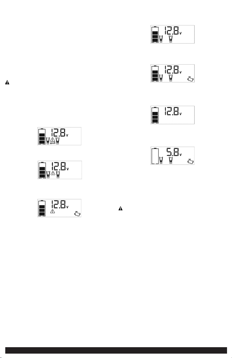
• If the clamps are connected incorrectly with regard to polarity, the unit will sound
a continuous alarm until the clamps are disconnected. The backlit LCD Screen will
display the Battery Status Icon, the Battery Voltage Indicator and the Clamp Icons.
The “+” and “–” signs above the Clamp Icons, the Arrow Icons and the Alarm Icon
will flash. The backlit LCD screen will display the following:
• If the red and black clamps touch each other, the unit will sound a continuous
two-second alarm every ten seconds until the clamps are separated. The backlit
LCD screen will display the following:
The Battery Status Icon and Battery Voltage Indicator light solid. The Alarm Icon,
Clamp Icons and the “+” and”–” signs will flash.
• If the unit is overheated during the jump starting process, the thermal protection
will activate and the backlit LCD screen will display the following:
The Battery Status Icon and Battery Voltage Indicator light solid. The Alarm Icon
and the jump starter icon will flash.
• Always disconnect the negative (black) jumper cable first, followed by the positive
(red) jumper cable, except for positive grounded systems.
Procedure
Take the following steps, observing all cautions and warnings in the “Important
Safety Instructions” section at the front of this manual.
1. Turn off vehicle ignition and all accessories (radio, A/C, lights, connected cell
phone chargers, etc.). Place vehicle in “park” and set the emergency brake.
2. Make sure the Jump-Starter Power Button is turned off.
3. Remove jumper clamps from clamp tabs. Connect the red clamp first, then the
black clamp.
4. Procedure for jump-starting a negative grounded system (negative battery
terminal is connected to chassis) (most common):
4a. Connect positive (+) red clamp to vehicle battery’s positive terminal.
4b. Connect negative (–) black clamp to chassis or a solid, non-moving, metal
vehicle component or body part. Never clamp directly to negative battery
terminal or moving part. Refer to the automobile owner’s manual.
5. Procedure for jump-starting positive ground systems:
NOTE: In the rare event that the vehicle to be started has a Positive Grounded System (positive battery
terminal is connected to chassis), replace steps 4a and 4b above with steps 5a and 5b, then
proceed to step 6.
5a. Connect negative (–) black clamp to vehicle battery’s negative terminal.
5b. Connect positive (+) red clamp to vehicle chassis or a solid, non-moving,
metal vehicle component or body part. Never clamp directly to positive
battery terminal or moving part. Refer to the automobile owner’s
manual.
6. When the clamps are connected properly, the backlit LCD screen will display
the following:
The Battery Status icon, Battery Voltage Indicator, Clamp Icons and the “+” and
“–” signs light solid.
7. Turn the Jump-Starter Power Button on. The backlit LCD screen will display the
following to indicate the unit is ready to jump-start:
The Battery Status icon, Battery Voltage Indicator, Clamp Icons and the “+” and
“–” signs light solid. The Jump Starter Icon will flash to indicate the clamps are
properly connected.
Note: If the Jump Starter Power Button has been pressed to turn the jump starter on and the clamps
are not connected to a battery, the backlit LCD screen will display the following:
The unit displays the Battery Status Icon and Battery Voltage Indicator for 10 seconds before
automatic shut down. Manufacturer suggests to always properly connect to a battery before
turning on the Jump Starter Power Button.
8. Turn on the ignition and crank the engine in 5-6 second bursts until engine
starts. The backlit LCD screen will display the following:
The Battery Status Icon, the Battery Voltage Indicator, Clamp Icons and the “+”
and”–” signs light solid to indicate the unit is jump-starting. The Jump Starter
Icon flashes. The Jump Starter Icon lights solid if vehicle is started.
9. Turn the Jump-Starter Power Button off.
10. Disconnect the negative (–) engine or chassis clamp first, then disconnect the
positive (+) battery clamp.
IMPORTANT: Always turn the unit off when not in use. Recharge this unit fully after
each use.
CAUTION – To reduce the risk of property damage:
• Vehicles that have on-board computerized systems may be damaged if vehicle
battery is jump-started. Before jump-starting this type of vehicle, read the vehicle
manual to confirm that external-starting assistance is advised.
• Excessive engine cranking can damage the vehicle‘s starter motor. If the engine
fails to start after the recommended number of attempts, discontinue jump-start
procedure and look for other problems that need to be corrected.
• If vehicle fails to start, turn off the ignition, turn off the Jump-Starter Power
Button, disconnect the jump-start system’s leads and contact a qualified technician
to investigate why the engine did not start.
AREA LIGHT
The area light is controlled by the Area Light Power Button on the Control Panel
(refer to the “Features” section to locate).
1. Press the Area Light Power Button once to turn the light on.
2. Press the Area Light Power Button again to turn the area light off.
When the Area Light Power Button is pressed to turn it on, a beep will sound. The
backlit LCD screen will turn on for 10 seconds (only) and will then continuously
display the Battery Status Icon and the Battery Voltage Indicator.
Periodically check the unit’s battery status on the backlit LCD screen. Four solid bars
in the battery icon indicates a full battery. When the battery level is nearly empty
with only one solid bar or completely empty with four empty bars, the unit must
be recharged at this time or the unit’s built-in low voltage protection will activate.
The empty Battery Status Icon will flash for a short period of time before automatic
shut down.
IMPORTANT: Make sure the Area Light is turned off when the unit is being
recharged or stored.
120 VOLT AC POWER OUTLET
Rated Versus Actual Current Draw of Equipment
Most electrical tools, appliances, electronic devices and audio/visual equipment
have labels that indicate the power consumption in amps or watts. Be sure that the
power consumption of the item to be operated is below 500 watts. If the power
consumption is rated in amps AC, simply multiply by the AC volts (120) to determine
the wattage.
Resistive loads are the easiest for this unit to run; however, it will not run larger
resistive loads (such as electric stoves and heaters), which require far more wattage
than the unit can deliver on a continuous basis. Inductive loads (such as TVs and
stereos) require more current to operate than do resistive loads of the same
wattage rating.
Power Inverter Output Waveform
The AC output waveform of this unit is known as a modified sine wave. It is a
stepped waveform that has characteristics similar to the sine wave shape of utility
power. This type of waveform is suitable for most AC loads, including linear and
switching power supplies used in electronic equipment, transformers, and small
motors.
Protective Features
The inverter monitors the following conditions:
Low internal battery voltage The inverter will automatically shut down when
the battery voltage drops too low, as this can
harm the battery.
High internal battery
voltage
The inverter will automatically shut down when
the battery voltage is too high, as this can harm
the unit.
Thermal shutdown
protection
The inverter will automatically shut down when
the unit becomes overheated.
Overload/short circuit
protection
The inverter will automatically shut down when an
overload or short circuit occurs.
IMPORTANT NOTES:
The AC Power Outlet provides a total power draw of 500W.
When the AC Power Outlet is in use, the unit will monitor for the following fault
conditions: thermal fault, low and high battery voltage fault, overload and short
circuit (refer to the “Protective Features” section).
1. If a low internal battery voltage fault condition exists, the AC Power Outlet will
shut down automatically and the backlit LCD screen will display the following
until the fault is corrected:
The Digital Display will show “AC”; the EMPTY Battery Status Icon and Fault
Icon on the LCD Screen will flash.
2. If the high internal battery voltage fault condition exists, the AC Power Outlet
will shut down automatically and the backlit LCD screen will display the
following until the fault is corrected:
The Digital Display will show “AC”; the FULL Battery Status Icon and Fault Icon
on the LCD Screen will flash.
3. If a thermal, overload or short circuit fault condition exists, the AC Power
Outlet will shut down automatically and the backlit LCD screen will display the
following until the fault is corrected:
The Battery Status Icon will light solid; the “AC” on the Digital Display and the
Fault Icon on the LCD Screen will flash.
Should any of the above fault conditions occur:
1. Disconnect the appliance from the unit.
2. Press the AC Power Button to turn the AC Power Outlet off.
3. Make sure the unit does not need to be recharged.
4. Allow the unit to cool down for several minutes.
5. Make sure the rating of the appliance plugged into the unit is 500 watts or
lower and that the appliance cord and plug are not damaged.
6. Assure there is adequate ventilation around the unit before proceeding.
Using the 120 Volt AC Outlet
The 120 Volt AC Outlet is located on the front of the unit. The outlet supports a
maximum power draw of 500 watts.
1. Press the AC Power Button to turn on the 120V AC Power Outlet. A beep will
sound and the LCD Screen will display the following:
The Battery Status Icon lights solid and the Digital Display shows “”AC”,
indicating the AC outlet is ready to use.
2. Insert the 120 volt AC plug from the appliance into the 120 Volt AC Outlet.
3. Switch on the appliance and operate as usual.
Note: Ensure that the wattage of the equipment plugged into the 120V AC Power Outlet does not
exceed 500 watts continuous.
4. Press the AC Power Button again to turn off the 120V AC Power Outlet.
Periodically check the unit’s battery status on the backlit LCD screen. Four solid bars
in the battery icon indicates a full battery. When the battery level is nearly empty
with only one solid bar or completely empty with 4 empty bars, the unit must be
recharged at this time or the unit’s built-in low voltage protection will activate. The
empty Battery Status Icon will flash for a short period of time before automatic
shut down.
IMPORTANT: Make sure the AC Power Outlet is turned off when the unit is being
recharged or stored.
USB PORTS
The USB Power Button and the three USB Ports are located on the front of the unit (refer to
the “Features” to locate).
IMPORTANT NOTES:
1. The three USB Ports provide 3.1A (5V) each.
2. When the USB Ports are in use, the unit will monitor for the following USB
fault conditions on all the USB Ports: low battery voltage fault, overload and
short circuit. In any of these cases, the backlit LCD screen will continuously
display the following:
The Fault Icon will flash. The USB Ports will automatically shut down. Should
this occur:
2a. Disconnect the USB-powered device and press the USB Power Button
again to turn off the USB Ports immediately.
2b. Make sure the unit does not need to be recharged.
2c. Allow the unit to cool down for several minutes before attempting to
use the USB Ports again.
2d. If a fault occurs again, make sure that the total draw of the USB device
plugged into the USB Port does not exceed 3.1A (5V). .
2e. If an individual USB device is within specifications and the fault occurs,
have the USB device checked for malfunction and do not continue to use
it with these USB Ports.
3. This unit’s USB Ports do not support data communication. They only provide
power to external USB-powered devices. The USB Ports provide 3.1A (5V) each.
4. Some household USB-powered electronics will not operate with this unit.
Using the USB Ports
1. Press the USB Power Button to turn on all of the USB Ports. A beep will sound.
The backlight will turn on for 10 seconds (only). The backlit LCD screen will
continuously display the following:
The Battery Status Icon and Battery Voltage Indicator will light solid, as well as
the USB Icon, indicating the USB ports are ready to use.
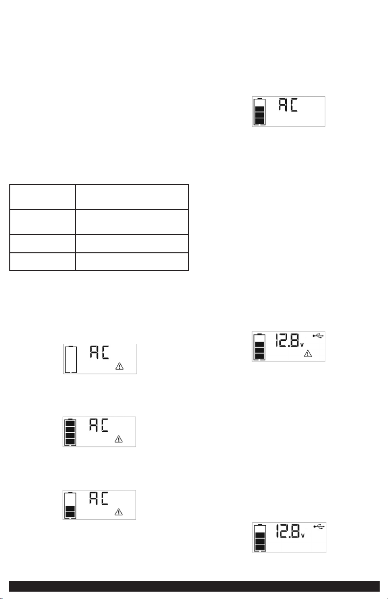
8 9
JUMP-STARTER
This unit is equipped with a Jump Starter Power Button that allows energy to flow
only when proper connections are made to the battery and frame.
A. For negative-grounded systems, connect the positive (red) clamp to the positive
ungrounded battery post and the negative (black) clamp to the vehicle chassis
or engine block away from the battery. Do not connect the clamp to the
carburetor, fuel lines or sheet-metal body parts. Connect to a heavy gauge
metal part of the frame or engine block.
B. For positive-grounded systems, connect the negative (black) clamp to the
negative ungrounded battery post and the positive (red) clamp to the vehicle
chassis or engine block away from the battery. Do not connect the clamp to
the carburetor, fuel lines or sheet-metal body parts. Connect to a heavy gauge
metal part of the frame or engine block.
IMPORTANT: Make sure the Compressor Power Button has been turned off before
attempting to use the unit as a Jump Starter.
WARNING – To reduce the risk of serious injury or property damage:
• Follow all safety instructions found in the “Specific Safety Instructions for Jump-
Starters” section of this instruction manual.
• Never touch red and black clamps together. This can cause dangerous sparks,
power arcing, and/or explosion.
• If the clamps are connected incorrectly with regard to polarity, the unit will sound
a continuous alarm until the clamps are disconnected. The backlit LCD Screen will
display the Battery Status Icon, the Battery Voltage Indicator and the Clamp Icons.
The “+” and “–” signs above the Clamp Icons, the Arrow Icons and the Alarm Icon
will flash. The backlit LCD screen will display the following:
• If the red and black clamps touch each other, the unit will sound a continuous
two-second alarm every ten seconds until the clamps are separated. The backlit
LCD screen will display the following:
The Battery Status Icon and Battery Voltage Indicator light solid. The Alarm Icon,
Clamp Icons and the “+” and”–” signs will flash.
• If the unit is overheated during the jump starting process, the thermal protection
will activate and the backlit LCD screen will display the following:
The Battery Status Icon and Battery Voltage Indicator light solid. The Alarm Icon
and the jump starter icon will flash.
• Always disconnect the negative (black) jumper cable first, followed by the positive
(red) jumper cable, except for positive grounded systems.
Procedure
Take the following steps, observing all cautions and warnings in the “Important
Safety Instructions” section at the front of this manual.
1. Turn off vehicle ignition and all accessories (radio, A/C, lights, connected cell
phone chargers, etc.). Place vehicle in “park” and set the emergency brake.
2. Make sure the Jump-Starter Power Button is turned off.
3. Remove jumper clamps from clamp tabs. Connect the red clamp first, then the
black clamp.
4. Procedure for jump-starting a negative grounded system (negative battery
terminal is connected to chassis) (most common):
4a. Connect positive (+) red clamp to vehicle battery’s positive terminal.
4b. Connect negative (–) black clamp to chassis or a solid, non-moving, metal
vehicle component or body part. Never clamp directly to negative battery
terminal or moving part. Refer to the automobile owner’s manual.
5. Procedure for jump-starting positive ground systems:
NOTE: In the rare event that the vehicle to be started has a Positive Grounded System (positive battery
terminal is connected to chassis), replace steps 4a and 4b above with steps 5a and 5b, then
proceed to step 6.
5a. Connect negative (–) black clamp to vehicle battery’s negative terminal.
5b. Connect positive (+) red clamp to vehicle chassis or a solid, non-moving,
metal vehicle component or body part. Never clamp directly to positive
battery terminal or moving part. Refer to the automobile owner’s
manual.
6. When the clamps are connected properly, the backlit LCD screen will display
the following:
The Battery Status icon, Battery Voltage Indicator, Clamp Icons and the “+” and
“–” signs light solid.
7. Turn the Jump-Starter Power Button on. The backlit LCD screen will display the
following to indicate the unit is ready to jump-start:
The Battery Status icon, Battery Voltage Indicator, Clamp Icons and the “+” and
“–” signs light solid. The Jump Starter Icon will flash to indicate the clamps are
properly connected.
Note: If the Jump Starter Power Button has been pressed to turn the jump starter on and the clamps
are not connected to a battery, the backlit LCD screen will display the following:
The unit displays the Battery Status Icon and Battery Voltage Indicator for 10 seconds before
automatic shut down. Manufacturer suggests to always properly connect to a battery before
turning on the Jump Starter Power Button.
8. Turn on the ignition and crank the engine in 5-6 second bursts until engine
starts. The backlit LCD screen will display the following:
The Battery Status Icon, the Battery Voltage Indicator, Clamp Icons and the “+”
and”–” signs light solid to indicate the unit is jump-starting. The Jump Starter
Icon flashes. The Jump Starter Icon lights solid if vehicle is started.
9. Turn the Jump-Starter Power Button off.
10. Disconnect the negative (–) engine or chassis clamp first, then disconnect the
positive (+) battery clamp.
IMPORTANT: Always turn the unit off when not in use. Recharge this unit fully after
each use.
CAUTION – To reduce the risk of property damage:
• Vehicles that have on-board computerized systems may be damaged if vehicle
battery is jump-started. Before jump-starting this type of vehicle, read the vehicle
manual to confirm that external-starting assistance is advised.
• Excessive engine cranking can damage the vehicle‘s starter motor. If the engine
fails to start after the recommended number of attempts, discontinue jump-start
procedure and look for other problems that need to be corrected.
• If vehicle fails to start, turn off the ignition, turn off the Jump-Starter Power
Button, disconnect the jump-start system’s leads and contact a qualified technician
to investigate why the engine did not start.
AREA LIGHT
The area light is controlled by the Area Light Power Button on the Control Panel
(refer to the “Features” section to locate).
1. Press the Area Light Power Button once to turn the light on.
2. Press the Area Light Power Button again to turn the area light off.
When the Area Light Power Button is pressed to turn it on, a beep will sound. The
backlit LCD screen will turn on for 10 seconds (only) and will then continuously
display the Battery Status Icon and the Battery Voltage Indicator.
Periodically check the unit’s battery status on the backlit LCD screen. Four solid bars
in the battery icon indicates a full battery. When the battery level is nearly empty
with only one solid bar or completely empty with four empty bars, the unit must
be recharged at this time or the unit’s built-in low voltage protection will activate.
The empty Battery Status Icon will flash for a short period of time before automatic
shut down.
IMPORTANT: Make sure the Area Light is turned off when the unit is being
recharged or stored.
120 VOLT AC POWER OUTLET
Rated Versus Actual Current Draw of Equipment
Most electrical tools, appliances, electronic devices and audio/visual equipment
have labels that indicate the power consumption in amps or watts. Be sure that the
power consumption of the item to be operated is below 500 watts. If the power
consumption is rated in amps AC, simply multiply by the AC volts (120) to determine
the wattage.
Resistive loads are the easiest for this unit to run; however, it will not run larger
resistive loads (such as electric stoves and heaters), which require far more wattage
than the unit can deliver on a continuous basis. Inductive loads (such as TVs and
stereos) require more current to operate than do resistive loads of the same
wattage rating.
Power Inverter Output Waveform
The AC output waveform of this unit is known as a modified sine wave. It is a
stepped waveform that has characteristics similar to the sine wave shape of utility
power. This type of waveform is suitable for most AC loads, including linear and
switching power supplies used in electronic equipment, transformers, and small
motors.
Protective Features
The inverter monitors the following conditions:
Low internal battery voltage The inverter will automatically shut down when
the battery voltage drops too low, as this can
harm the battery.
High internal battery
voltage
The inverter will automatically shut down when
the battery voltage is too high, as this can harm
the unit.
Thermal shutdown
protection
The inverter will automatically shut down when
the unit becomes overheated.
Overload/short circuit
protection
The inverter will automatically shut down when an
overload or short circuit occurs.
IMPORTANT NOTES:
The AC Power Outlet provides a total power draw of 500W.
When the AC Power Outlet is in use, the unit will monitor for the following fault
conditions: thermal fault, low and high battery voltage fault, overload and short
circuit (refer to the “Protective Features” section).
1. If a low internal battery voltage fault condition exists, the AC Power Outlet will
shut down automatically and the backlit LCD screen will display the following
until the fault is corrected:
The Digital Display will show “AC”; the EMPTY Battery Status Icon and Fault
Icon on the LCD Screen will flash.
2. If the high internal battery voltage fault condition exists, the AC Power Outlet
will shut down automatically and the backlit LCD screen will display the
following until the fault is corrected:
The Digital Display will show “AC”; the FULL Battery Status Icon and Fault Icon
on the LCD Screen will flash.
3. If a thermal, overload or short circuit fault condition exists, the AC Power
Outlet will shut down automatically and the backlit LCD screen will display the
following until the fault is corrected:
The Battery Status Icon will light solid; the “AC” on the Digital Display and the
Fault Icon on the LCD Screen will flash.
Should any of the above fault conditions occur:
1. Disconnect the appliance from the unit.
2. Press the AC Power Button to turn the AC Power Outlet off.
3. Make sure the unit does not need to be recharged.
4. Allow the unit to cool down for several minutes.
5. Make sure the rating of the appliance plugged into the unit is 500 watts or
lower and that the appliance cord and plug are not damaged.
6. Assure there is adequate ventilation around the unit before proceeding.
Using the 120 Volt AC Outlet
The 120 Volt AC Outlet is located on the front of the unit. The outlet supports a
maximum power draw of 500 watts.
1. Press the AC Power Button to turn on the 120V AC Power Outlet. A beep will
sound and the LCD Screen will display the following:
The Battery Status Icon lights solid and the Digital Display shows “”AC”,
indicating the AC outlet is ready to use.
2. Insert the 120 volt AC plug from the appliance into the 120 Volt AC Outlet.
3. Switch on the appliance and operate as usual.
Note: Ensure that the wattage of the equipment plugged into the 120V AC Power Outlet does not
exceed 500 watts continuous.
4. Press the AC Power Button again to turn off the 120V AC Power Outlet.
Periodically check the unit’s battery status on the backlit LCD screen. Four solid bars
in the battery icon indicates a full battery. When the battery level is nearly empty
with only one solid bar or completely empty with 4 empty bars, the unit must be
recharged at this time or the unit’s built-in low voltage protection will activate. The
empty Battery Status Icon will flash for a short period of time before automatic
shut down.
IMPORTANT: Make sure the AC Power Outlet is turned off when the unit is being
recharged or stored.
USB PORTS
The USB Power Button and the three USB Ports are located on the front of the unit (refer to
the “Features” to locate).
IMPORTANT NOTES:
1. The three USB Ports provide 3.1A (5V) each.
2. When the USB Ports are in use, the unit will monitor for the following USB
fault conditions on all the USB Ports: low battery voltage fault, overload and
short circuit. In any of these cases, the backlit LCD screen will continuously
display the following:
The Fault Icon will flash. The USB Ports will automatically shut down. Should
this occur:
2a. Disconnect the USB-powered device and press the USB Power Button
again to turn off the USB Ports immediately.
2b. Make sure the unit does not need to be recharged.
2c. Allow the unit to cool down for several minutes before attempting to
use the USB Ports again.
2d. If a fault occurs again, make sure that the total draw of the USB device
plugged into the USB Port does not exceed 3.1A (5V). .
2e. If an individual USB device is within specifications and the fault occurs,
have the USB device checked for malfunction and do not continue to use
it with these USB Ports.
3. This unit’s USB Ports do not support data communication. They only provide
power to external USB-powered devices. The USB Ports provide 3.1A (5V) each.
4. Some household USB-powered electronics will not operate with this unit.
Using the USB Ports
1. Press the USB Power Button to turn on all of the USB Ports. A beep will sound.
The backlight will turn on for 10 seconds (only). The backlit LCD screen will
continuously display the following:
The Battery Status Icon and Battery Voltage Indicator will light solid, as well as
the USB Icon, indicating the USB ports are ready to use.
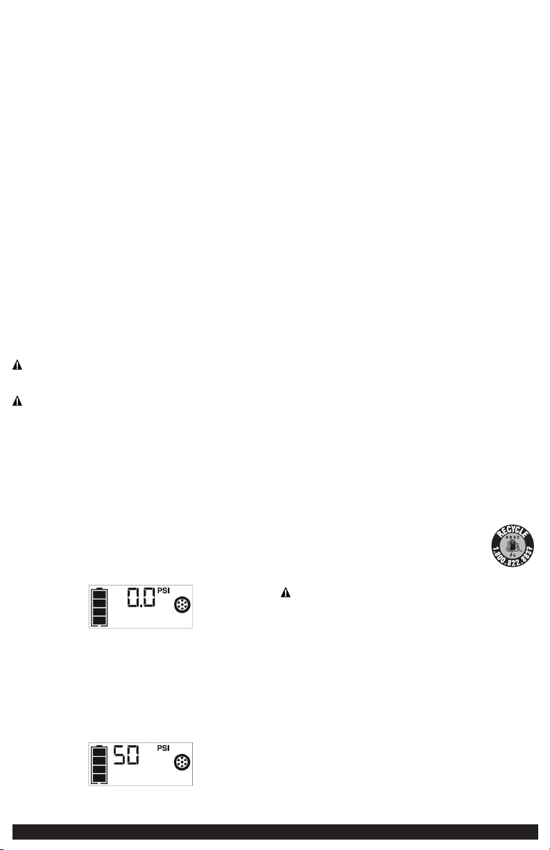
10 11
2. Plug the USB-powered device into the USB power port(s) and operate normally.
3. Press the USB Power Button again to turn off the USB Ports.
Periodically check the unit’s battery status on the backlit LCD screen. Four solid bars
in the battery icon indicates a full battery. When the battery level is nearly empty
with only one solid bar or completely empty with 4 empty bars, the unit must be
recharged at this time or the unit’s built-in low voltage protection will activate. The
empty Battery Status Icon will flash for a short period of time before automatic
shut down.
IMPORTANT: Make sure the USB Ports are turned off when the unit is being
recharged or stored.
PORTABLE COMPRESSOR
The built-in 12 volt DC compressor is the ultimate compressor for all vehicle tires,
trailer tires and recreational inflatables. A nozzle adaptor is supplied that screws
onto the end of the Sure Fit
®
nozzle at the free end of the compressor hose.
The compressor hose with tire fitting is stored in the compressor hose storage
compartment. Refer to the “Features” illustration for locations of compressor
hose. The Compressor Power Button and Increase (+) and Decrease (–) Compressor
Pressure Control Buttons are located on the control panel on the front of the unit.
Before proceeding, check the unit’s battery status on the LCD screen. Four solid bars
in the battery icon indicates a full battery. When the battery level is nearly empty
with only one solid bar, the unit MUST be recharged before use or the unit’s built-in
low voltage protection will activate. The empty Battery Status Icon will flash for a
short period of time before automatic shut down.
The compressor is capable of inflating up to 120 pounds per square inch (psi)
pressure. The compressor can operate long enough to fill up to 3 average sized tires
before the battery must be recharged. Return hose to the storage compartment
after use.
IMPORTANT: Make sure the Jump Starter Power Button has been turned off before
attempting to use the unit as a Compressor.
WARNING – TO REDUCE THE RISK OF SERIOUS INJURY OR PROPERTY
DAMAGE: Follow all safety instructions found in the “Specific Safety Instructions for
Compressors” section of this instruction manual.
CAUTION – TO REDUCE THE RISK OF SERIOUS INJURY OR PROPERTY
DAMAGE: When the compressor is operated at a low PSI, the unit may start in low
and gradually rev up. When the compressor is operated at higher PSIs, the unit
may operate normally for several minutes, then rev down for a few minutes before
returning to normal operation. This feature protects the unit from overheating
during normal use. In any event, do not operate compressor continuously for
longer than 10 minutes, as it may overheat. This could damage the compressor. If
the compressor must be operated for longer periods: every 10 minutes press the
Compressor Power Button to turn the compressor off, then restart after a cooling
down period of approximately 30 minutes.
In any event, the compressor will automatically shut down after operating
continuously for 10 minutes
Inflating Tires or Products With Valve Stems
1. Screw the Sure Fit
®
nozzle onto the valve stem. Do not overtighten.
2. Press the Compressor Power Button. A beep will sound and the backlit LCD
screen will display the following:
The Compressor Icon will light and the digital display will alternately show the
flashing pre-set psi value (that was last set by the compressor pressure control
buttons) and the current pressure of the item being inflated (which will light
solid).
3. Press the “+” and “–” Pressure Control Buttons to set the desired pressure from
a range pre-set values (between 1 and 120), which will display on the backlit
LCD screen. The unit will sound a beep with each press of the buttons (holding
the button speeds up the upward or downward value selection). Once the
desired pressure has been entered, release the button and the flashing digital
display will show the new selected pressure, as follows:
The new selected value is now stored in the unit’s memory until it is manually
reset.
4. Press the Compressor Power Button once more to begin inflating. The
Compressor Icon will flash and the digital display will only show the current
pressure value (which will light solid) to indicate the compressor is activated.
Monitor the pressure on the LCD screen.
IMPORTANT NOTE: To interrupt during inflation, press the Compressor Power
Button again.
5. When desired pre-set pressure is reached, the compressor will automatically stop.
6. Press the Compressor Power Button again to turn off the unit.
7. Unscrew and remove the Sure Fit
®
nozzle from the valve stem.
8. Allow the unit to cool, then recharge before storing away.
9. Store the compressor hose and Sure Fit
®
nozzle in storage compartment.
Inflating Other Inflatables Without Valve Stems
Inflation of other items requires use of the nozzle adapter.
1. Screw the nozzle adapter into the Sure Fit
®
nozzle. Do not overtighten.
2. Insert the nozzle adapter into item to be inflated.
3. Follow steps 2 through 4 of the “Inflating Tires or Products With Valve
Stems” section.
IMPORTANT: Small items such as volleyballs, footballs, etc. inflate very rapidly.
Keep this in mind when setting pressure. Take extra care not to over-inflate.
4. When the desired pressure is reached, the compressor will automatically stop.
Press the Compressor Power Button again to turn off the unit.
5. Disconnect the adapter from the inflated item.
6. Unscrew and remove the nozzle adapter from the Sure Fit
®
nozzle.
7. Allow the unit to cool, then recharge before storing away.
8. Store the compressor hose, Sure Fit
®
nozzle and nozzle adapter in the storage
compartment when not in use.
CARE AND MAINTENANCE
All batteries lose energy from self-discharge over time and more rapidly at higher
temperatures. When the unit is not in use, we recommend that the battery is
charged at least every 30 days.
Never submerge the unit in water. If the unit gets dirty, gently clean the outer
surfaces of the unit with a soft cloth.
There are no user-replaceable parts. Periodically inspect the condition of adapters,
connectors and wires. Contact manufacturer to replace any components that have
become worn or broken.
Battery
Please be advised that the battery is designed to last the service life of the unit and
is not replaceable, removable or serviceable. Service life is dependent on a number
of factors including but not limited to the number of recharge cycles, and proper
care and maintenance of the battery by the end user. Contact manufacturer for any
information you may need.
SAFE BATTERY DISPOSAL
Contains a maintenance-free, sealed, non-spillable, lead acid
battery, which must be disposed of properly. Recycling is
required. Failure to comply with local, state and federal
regulations can result in fines, or imprisonment.
Please recycle.
WARNINGS:
• Do not dispose of the battery in fire as this may result in an explosion.
• Before disposing of the battery, protect exposed terminals with heavy-duty
electrical tape to prevent shorting (shorting can result in injury or fire).
• Do not expose battery to fire or intense heat as it may explode.
TROUBLESHOOTING
Unit will not charge
• Make sure the AC Power Button has been pressed to turn the inverter off.
• Make sure a suitable gauge extension cord is properly connected to both the unit
and a functioning AC outlet.
Unit fails to jump-start
• Make sure the unit is not being operated in the Compressor mode.
• Make sure unit’s Jump-Starter Power Button is in the ON position.
• Make sure a proper polarity cable connection has been established.
• The unit may be overheated due to the excessive engine cranking. Make sure all
the unit functions are turned off and allow the unit to cool down before resuming
operation.
• Check that unit has a full charge. Recharge unit if necessary.
120 volt AC outlet will not power appliance
• Make sure the unit is not being operated in the Jump Start mode
• Make sure the AC Power Button has been pressed to turn the inverter on.
• Make sure you have followed all the steps in the “120 AC Power Outlet” section
carefully. Refer to the important notes included in that section that explain
common problems and solutions.
• Make sure the appliance being powered does not draw more than 500 watts
• Refer to the important notes included in that section that explain common problems
and solutions.
• Check that unit has a full charge. Recharge unit if necessary.
USB power port will not power appliance
• Make sure the USB Power Button has been pressed to turn the USB Ports on.
• If a fault condition exists in any of the USB Ports, the Fault Icon on the LCD screen
will flash. Refer to the Important Notes in the “USB Ports” section to remedy any
faults.
• Make sure that the total draw the USB device plugged into the USB Port does not
exceed 3.1A (5V).
• Some USB-powered household electronics will not operate with this USB charging/
power port. Check the manual of the corresponding electronic device to confirm
that it can be used with this type of USB charging/power port.
• Check that unit has a full charge. Recharge unit if necessary.
LED area light does not come on
• Make sure the area light power button has been pressed to turn the area light on.
• Check that unit has a full charge. Recharge unit if necessary.
Portable compressor will not inflate
• Make sure the unit is not being operated in the Jump Starter mode.
• Make sure the compressor power button has been pressed to turn the compressor on.
• Make sure the Sure Fit
®
nozzle connector is securely screwed on to the valve stem
when attempting to inflate tires; or that the nozzle adapter is securely screwed
into the Sure Fit
®
nozzle connector and is inserted properly into the item to be
inflated on all other inflatables.
• The compressor may be overheated. Press the compressor power button to turn the
compressor off. Restart after a cooling down period of approximately 30 minutes.
• Check that unit has a full charge. Recharge unit if necessary.
ACCESSORIES
Recommended accessories for use with your tool may be available from the
manufacturer. If you need assistance regarding accessories, please contact the
manufacturer at 1-877-571-2391.
The use of any accessory not recommended for use with this appliance could
be hazardous.
SERVICE INFORMATION
Whether you need technical advice, repair, or genuine factory replacement parts,
contact the manufacturer at 1-877-571-2391.
FULL ONE-YEAR HOME USE WARRANTY
The manufacturer warrants this product against defects in materials and
workmanship for a period of ONE (1) YEAR from the date of retail purchase by the
original end-user purchaser (“Warranty Period”).
If there is a defect and a valid claim is received within the Warranty Period, the
defective product can be replaced or repaired in the following ways: (1) Return the
product to the manufacturer for repair or replacement at manufacturer’s option.
Proof of purchase may be required by manufacturer. (2) Return the product to the
retailer where product was purchased for an exchange (provided that the store is a
participating retailer). Returns to retailer should be made within the time period of
the retailer’s return policy for exchanges only (usually 30 to 90 days after the sale).
Proof of purchase may be required. Please check with the retailer for their specific
return policy regarding returns that are beyond the time set for exchanges.
This warranty does not apply to accessories, bulbs, fuses and batteries; defects
resulting from normal wear and tear, accidents; damages sustained during shipping;
alterations; unauthorized use or repair; neglect, misuse, abuse; and failure to follow
instructions for care and maintenance for the product.
This warranty gives you, the original retail purchaser, specific legal rights and you
may have other rights which vary from state to state or province to province. This
product is not intended for commercial use.
Be sure to register your product at https://www.baccusglobal.com/registration to
receive important product information, special promotions and offers, and more.
SPECIFICATIONS
Boost Ampere: 12V DC, 1200A peak battery,
600A instantaneous
Battery Type: Maintenance-free, sealed lead acid,
12V DC
AC Input: 120V AC, 60Hz, 13W
Area Light: 1 white LED
USB Ports: 3.1A max., 5V DC
AC Outlet: 120V AC, 60Hz, 500W continuous
Compressor Maximum Pressure: 120 PSI
Sure Fit
®
is a registered U.S. trademark owned by Baccus Global, LLC.
STANLEY
®
AND THE STANLEY
®
LOGO ARE REGISTERED
TRADEMARKS OF STANLEY BLACK + DECKER INC.
OR ONE OF ITS AFFILIATES, AND ARE
USED UNDER LICENSE.
Imported by Baccus Global LLC,
621 NW 53rd St., Suite 450, Boca Raton, FL 33487
www.baccusglobal.com 1-877-571-2391
RD090921

1312
NORMAS DE
SEGURIDAD /
DEFINICIONES
PELIGRO: Indica una situación de peligro inminente que, si no se evita,
provocará la muerte o lesiones graves.
ADVERTENCIA: Indica una situación de peligro inminente que, si no se evita,
puede provocar la muerte o lesiones graves.
PRECAUCIÓN: Indica una situación de peligro potencial que, si no se evita,
puede provocar lesiones leves o moderadas.
Usado sin la palabra, indica un mensaje relacionado con la seguridad.
AVISO: Indica una práctica no relacionada con lesiones personales que, si no se
evita, puede resultar en daños a la propiedad.
RIESGO DE OPERACIÓN INSEGURA. Cuando se utilizan herramientas o
equipos, siempre se deben respetar las precauciones de seguridad para reducir el
riesgo de lesiones personales. La operación, el mantenimiento o la modificación
incorrectos de herramientas o equipos pueden provocar lesiones graves y daños a la
propiedad. Las herramientas y los equipos están diseñados para usos determinados.
Fabricante recomienda encarecidamente que NO se modifique este producto y
que NO se utilice para ningún otro uso que aquél para el que fue diseñado. Lea
y comprenda todas las instrucciones operativas y las advertencias antes de utilizar
cualquier herramienta o equipo.
LEA TODAS LAS
INSTRUCCIONES
ADVERTENCIA: Lea y comprenda este manual de instrucciones antes de
utilizar esta unidad. El incumplimiento de todas las instrucciones enumeradas a
continuación puede provocar una descarga eléctrica, un incendio o lesiones graves.
INSTRUCCIONES
IMPORTANTES DE
SEGURIDAD
ADVERTENCIAS E INSTRUCCIONES DE SEGURIDAD
GENERALES
• Esta unidad fue diseñada para el uso domestico.
ADVERTENCIA – Riesgo de incendios, descargas eléctricas, peligro de
explosión o lesiones a personas o propiedades:
• Evite las condiciones ambientales peligrosas. No utilice artefactos en zonas
húmedas o mojadas. No utilice artefactos bajo la lluvia.
• Mantenga a los niños alejados. Los visitantes deben mantenerse a cierta distancia
del área de trabajo.
• Use la vestimenta adecuada. No use ropas holgadas o joyas. Pueden atascarse
en las piezas en movimiento. Se recomienda utilizar guantes de goma y calzado
antideslizante considerable al trabajar al aire libre. Recójase y cubra el cabello
largo.
• Guarde los artefactos que no utilice en el interior. Cuando no los utilice, los
artefactos deben guardarse bajo techo, en un lugar seco, alto o bajo llave, lejos del
alcance de los niños.
• No tire del cable. Nunca transporte el aparato por el cable ni lo jale para
desconectarlo del tomacorriente. Mantenga el cable alejado del calor, el aceite y
los bordes afilados.
• Desconecte los aparatos. Desconecte el aparato de la fuente de energía cuando no
lo utilice, antes de realizar un mantenimiento y al cambiar accesorios como hojas y
elementos semejantes.
• La protección del interruptor de corte por falla a tierra (GFCI) debe aplicarse a los
circuitos o los tomacorrientes que se utilizarán. Hay tomacorrientes con protección
GFCI incorporada que pueden utilizarse para tomar esta medida de seguridad.
• Uso de accesorios y suplementos. El uso de accesorios o dispositivos no
recomendados para utilizar con este aparato puede resultar peligroso. Consulte la
sección “Accesorios” de este manual para obtener detalles adicionales.
• Manténgase alerta. Use el sentido común. No opere este equipo si está cansado o
con impedimentos.
• Compruebe para saber si hay piezas dañadas. Cualquier parte que esté dañada
debe ser reemplazado por el fabricante antes de su uso posterior. No utilice
la herramienta si el interruptor no le da vuelta por intervalos. Contacto con el
fabricante en 1-877-571-2391 para más información.
• No funcione el aparato cerca de líquidos inflamables o en atmósferas gaseosas o
explosivas. Los motores de estas herramientas normalmente chispean, y las chispas
pueden encender los vapores.
• Nunca sumerja esta unidad en agua; no la exponga a la lluvia, la nieve, ni la use
cuando esté mojada.
• Para reducir el riesgo de descarga eléctrica, desconecte la unidad de cualquier
fuente de energía antes de intentar limpiarla o realizarle un mantenimiento.
Apagar los controles sin desenchufar la unidad no reducirá este riesgo.
• Este equipo emplea piezas (interruptores y relés) que producen arcos o chispas.
Por lo tanto, si utiliza la unidad en una cochera o un área cerrada, DEBE colocarla
a no menos de 457 mm (18 pulgadas) por encima del piso.
• No inserte los objetos extranjeros en los puertos USB o los tomacorrientes de
120V CA.
INSTRUCCIONES DE SEGURIDAD ESPECÍFICAS PARA
CARGAR ESTA UNIDAD
• IMPORTANTE: Esta unidad se entrega en un estado parcialmente cargado. Cargue
por completo la unidad con un cable de extensión doméstico durante 40 horas
o hasta que el icono de estado de la batería muestre 4 barras sólidas antes de
usarlo por primera vez. No se puede exceso de carga la unidad con el método de
carga de CA.
• Para recargar esta unidad, utilice sólo el cargador incorporado CA.
• Todas las funciones deben apagarse cuando la unidad se está cargando o no está
en uso. Asegúrese de que todos los interruptores estén en la posición de apagado
(OFF) antes de realizar la conexión a una fuente de energía o carga.
CABLES DE EXTENSIÓN:
ADVERTENCIA: El uso de un cable de extensión incorrecta podría dar lugar
a un riesgo de fuego y descarga eléctrica. Al usar un cable de extensión, cerciórese
de que los pernos del cable de extensión son el mismo número, tamaño y forma
que ésos en el cargador; y esté seguro de utilizar uno bastante pesado para llevar
la corriente que su producto dibujará. Un cable de menor capacidad provocará una
disminución en el voltaje de la línea, lo cual producirá una pérdida de potencia y
sobrecalentamiento. La siguiente tabla muestra la medida correcta que debe utilizar
según la longitud del cable y la capacidad nominal en amperios indicada en la
placa. En caso de duda, utilice el calibre inmediatamente superior. Cuanto menor es
el número de calibre, más grueso es el cable.
CALIBRE MÍNIMO PARA LOS JUEGOS
DE CABLES
Voltios Largo total del cable en pies (metros)
120V 0-25 26-50 51-100 101-150
(0-7.6m) (7.6-15.2m) (15.2-30.4m) (30.4-45.7m)
240V 0-50 51-100 101-200 201-300
(0-15.2m) (15.2-30.4m) (30.4-60.9m) (60.9-91.4m)
Grado del amperio Longitud de la cable de extensión
Más No más
0’-25’ 26’-50’ 51’-100’ 101’ -150’
que que
Calibrador de alambre Americano
(AWG)
0 - 6 18 16 16 14
6 - 10 18 16 14 12
10 - 12 16 16 14 12
12 - 16 14 12 No recomendado
• Cuando se utiliza un cable prolongador, asegúrese de que:
– as patas del cable prolongador sean del mismo número, el mismo tamaño y la
misma forma que las del cargador,
– el cable prolongador posea los conductores correctos y esté en buenas
condiciones eléctricas,
– la medida del conductor sea suficientemente grande para la capacidad nominal
en amperios.
PRECAUCIÓN – Para reducir el riesgo de lesiones o daño a la propiedad:
Cuando desconecte el cable de extensión desde el cargador de CA de 120 voltios
incorporado o la toma de CA, tire por el conectador y no por el cable.

14 15
INSTRUCCIONES DE SEGURIDAD ESPECÍFICAS PARA
AUXILIARES DE ARRANQUE
ADVERTENCIA – Peligro de estallido:
No utilice la unidad para cargar las baterías secas que se usan normalmente con
los aparatos domésticos. Estas baterías pueden estallar y provocar lesiones a las
personas y daños a la propiedad. Use la unidad para carga/ refuerzo solamente de
una batería de plomo-ácido. No está diseñada para proveer energía a un sistema
eléctrico de bajo voltaje que no sea para arrancar un motor.
• El uso de un dispositivo no suministrado, recomendado o vendido por el fabricante
específicamente para el uso con esta unidad puede provocar riesgo de descarga
eléctrica y lesiones a las personas.
ADVERTENCIA – Riesgo de gases explosivos:
• Trabajar cerca de una batería de plomo ácido es peligroso. Las baterías generan
gases explosivos durante su funcionamiento normal. Por esta razón, es muy
importante que siempre lea este manual antes de utilizar el puente auxiliar de
arranque y que siga las instrucciones con exactitud.
• Para reducir el riesgo de explosión de la batería, siga estas instrucciones y las
publicadas por el fabricante de la batería y el fabricante de cualquier equipo que
tenga la intención de utilizar cerca de la batería. Revise las indicaciones sobre
precauciones en estos productos y en el motor.
PRECAUCIÓN – Para reducir el riesgo de lesiones o daño a la propiedad:
• NUNCA INTENTE ARRANCAR MEDIANTE PUENTE NI CARGAR UNA BATERÍA
CONGELADA.
• Los vehículos que tienen sistemas computarizados incorporados pueden resultar
dañados si la batería del vehículo se arranca mediante puente. Antes de arrancar
mediante puente, lea el manual del cliente del vehículo para confirmar que la
ayuda externa para arrancar es adecuada.
• Nunca fume o permita que haya una chispa o llama cerca de la batería, el motor
o la central de energía.
• Manténgase alejado de las paletas de ventilador, correas, poleas y otras partes que
pueden provocar lesiones a las personas.
• Tenga mucho cuidado de no dejar caer una herramienta de metal sobre la batería.
Puede ser que producir chispas o un cortocircuito en la batería o en otra parte
eléctrica y podría causar una explosión.
• Los procedimientos de arranque del motor sólo deben realizarse en un área
segura, seca y bien ventilada.
• Almacene siempre las pinzas de la batería cuando no se usa. Nunca toque las
pinzas de la batería entre sí. Esto puede generar chispas peligrosas, arcos eléctricos
o explosión.
• Cuando use esta unidad cerca de la batería y el motor del vehículo, coloque la
unidad sobre una superficie plana y estable, y asegúrese de mantener todas las
pinzas, los cables, la ropa y las partes del cuerpo alejados de los elementos móviles
del vehículo.
• Nunca deje que las pinzas roja y negra se toquen entre sí o con otro conductor
metálico común, esto podría provocar daños a la unidad o crear un riesgo de
chispas/explosión.
– Para los sistemas con negativo a tierra, conecte la pinza del positivo (roja) al
borne sin conexión a tierra de la batería y la pinza del negativo (NEGRA) al
bastidor del vehículo o al bloque del motor, lejos de la batería. No conecte
la pinza al carburador, las cañerías de combustible o a las piezas de chapa de
la carrocería. Conecte a una pieza de metal sólida del bastidor o del bloque
del motor.
– Para los sistemas con positivo a tierra, conecte la pinza del negativo (negra) al
borne sin conexión a tierra negativo de la batería y la pinza del positivo (roja)
al bastidor del vehículo o al bloque del motor, lejos de la batería. No conecte
la pinza al carburador, las cañerías de combustible o a las piezas de chapa de
la carrocería. Conecte a una pieza de metal sólida del bastidor o del bloque
del motor.
• Si las pinzas están conectadas incorrectamente con respecto a polaridad, la
pantalla LCD retroiluminada demostrará el icono de estado de la batería, el
indicador del voltaje, y los iconos de pinzas. El icono del fallo, las símbolos “+”
y “–” y los iconos de polaridad inversa destellará y la unidad emitirá una alarma
continua hasta que se desconectan las pinzas. Desconecte y vuelva a conectar las
pinzas de la batería con la polaridad correcta.
• Siempre desconecte primero el cable del puente del negativo (negro) y luego el
cable del puente del positivo (rojo), excepto para los sistemas con positivo a tierra.
• No exponga la batería al fuego o a un calor intenso, porque puede explotar. Antes
de eliminar la batería, proteja los terminales expuestos con cinta aislante para
trabajo pesado para evitar cortocircuitos (un cortocircuito puede producir lesiones
o incendio).
• Coloque esta unidad lo más lejos posible de la batería que los cables permitan.
• Nunca permita que el ácido de la batería entre en contacto con esta unidad.
• No opere esta unidad en un área cerrada ni restrinja la ventilación de alguna
forma.
• Este sistema está diseñado para ser utilizado únicamente en vehículos con sistema
de batería de CC de 12 voltios. No lo conecte a un sistema de batería de 6 o 24
voltios.
• Este sistema no está diseñado para ser utilizado en reemplazo de una batería de
vehículo. No intente hacer funcionar un vehículo que no tenga la batería instalada.
• El exceso de revoluciones del motor puede dañar el mecanismo de arranque de un
vehículo. Si el motor no arranca después de la cantidad recomendada de intentos,
abandone los procedimientos de arranque mediante puente y busque otros
problemas que deban solucionarse.
• No utilice este puente auxiliar de arranque en una moto de agua. No fue diseñado
para prácticas marinas.
• Si bien esta unidad contiene una batería que no derrama, se recomienda que la
unidad se conserve parada durante el almacenamiento, el uso y la recarga. Para
evitar daños posibles que puedan acortar la duración de la unidad, protéjala de la
luz solar directa, el calor directo o la humedad.
INSTRUCCIONES DE SEGURIDAD ESPECÍFICAS PARA
INVERTIDORES
ADVERTENCIA – Para reducir el riesgo de descarga eléctrica:
• No conecte al cableado de distribución de CA.
• No realice conexiones o desconexiones eléctricas en áreas designadas como
PROTEGIDAS CONTRA IGNICIÓN. Esta unidad NO está aprobada para áreas
protegidas contra ignición.
• Nunca sumerja la unidad en el agua ni en ningún otro líquido, ni la utilice cuando
esté húmeda.
• No inserte los objetos extranjeros en los enchufes de CA de la unidad.
ADVERTENCIA – Para reducir el riesgo de incendio:
• No opere cerca de materiales, vapores o gases inflamables.
• No lo exponga al calor extremo o a las llamas.
PRECAUCIÓN – Para reducir el riesgo de lesiones o daño a la propiedad:
• Desconecte el enchufe de la aplicación del enchufe del convertidor antes de
intentar cualesquiera reparaciones a la aplicación.
• Cuando un artefacto conectado a esta unidad se usa al aire libre, utilice sólo cables
de extensión diseñados para uso en exteriores y marcado.
• No intente conectar el inversor mientras que funciona su vehículo. El hecho de no
prestar atención a la carretera puede tener como consecuencia un accidente grave.
• Siempre utilice el convertidor en lugares adecuadamente ventilados.
• Apague siempre el convertidor cuando es parado.
• Tenga en cuenta que este convertidor no funcionará con aparatos o equipos de
alta potencia en vatios que produzcan calor, como secadores de cabello, hornos de
microondas y tostadores.
• No utilice este convertidor con dispositivos médicos. No se ha comprobado su
funcionamiento en aplicaciones médicas.
• Algunas computadoras portátiles no funcionen con este inversor.
• Opere la unidad solamente como se describe en este manual de instrucciones.
PRECAUCIÓN – Dispositivos recargables:
• Algunos dispositivos recargables están diseñados para cargarse al ser enchufados
directamente en un tomacorriente de CA. Estos dispositivos pueden dañar el
inversor o el circuito que se está cargando.
• Al utilizar un dispositivo recargable, supervise la temperatura durante los primeros
10 minutos de uso para determinar si genera calor en exceso.
• Si produce calor en exceso, esto indica que el dispositivo no debe utilizarse con
este inversor.
• Este problema no se presenta con la mayoría de los equipos operados con batería.
La mayoría de estos dispositivos utiliza un cargador o transformador por separado
que está enchufado en un tomacorriente de CA.
• El inversor puede funcionar con la mayoría de los cargadores y transformadores.
INSTRUCCIONES DE SEGURIDAD ESPECÍFICAS PARA EL
PUERTOS USB
• No introduzca objetos extraños dentro ya sea el puertos USB.
• No conecte un concentrador USB y no conecte más de un dispositivo electrónico
personal a cada puerto USB.
• No use esta unidad para operar dispositivos que requieren más de 3.1A (5V) para
operar desde cada uno de los puertos USB.
• Una cierta electrónica USB-accionada hogar no funcionará con esta unidad.
INSTRUCCIONES DE SEGURIDAD ESPECÍFICAS PARA
COMPRESORES
PPRECAUCIÓN – Para reducir el riesgo de lesiones o daño a la propiedad:
• Nunca deje el compresor sin supervisión mientras se está usando.
• No funcione el aparato para inflar con aire continuamente por más de largo que
aproximadamente 10 minutos, dependiendo de temperaturas ambiente, como
puede recalentarse. Esto podría dañar el compresor. Siga las instrucciones de la
sección “Compresor portátil.”
ADVERTENCIA – Peligro de estallido: Los artículos que estallan pueden
provocar lesiones graves.
• Siga cuidadosamente las instrucciones en los artículos de ser inflado.
• Nunca exceda la presión recomendada enumerada en instrucciones en los artículos
de ser inflado. Si no se da ninguna presión, contacto con el fabricante del artículo
antes de inflar.
• Supervise la presión siempre sobre la pantalla LCD retroiluminada.
PRIMEROS AUXILIOS
Cuando trabaje con baterías de plomo-ácido, asegúrese de que siempre haya ayuda
inmediata disponible en caso de accidente o emergencia.
Quítese los elementos personales metálicos, como anillos, pulseras, collares y relojes
cuando trabaja con una batería de plomo-ácido. Una batería de plomo-ácido puede
producir un cortocircuito con bastante corriente como para soldar un anillo u objeto
metálico similar a la piel y provocar una quemadura grave.
No use ropa de vinilo cuando arranque un vehículo mediante puente. La fricción
puede provocar chispas peligrosas a causa de la electricidad estática.
Utilice siempre protección para los ojos al emplear este producto; el contacto con
el ácido de la batería puede producir ceguera o quemaduras graves. Conozca los
procedimientos de primeros auxilios para el caso de contacto accidental con el ácido
de la batería.
Tenga al alcance mucha agua potable y jabón en el caso de que el ácido de la
batería entre en contacto con la piel.
• Piel: Si el ácido de la batería entra en contacto con la piel, enjuáguese
inmediatamente con agua, luego lávese con agua y jabón. Si se presenta
enrojecimiento, dolor o irritación, busque asistencia médica de inmediato.
• Ojos: Si el ácido de la batería entra en contacto con los ojos, lávese los ojos
inmediatamente durante 15 minutos como mínimo y busque asistencia médica
de inmediato.
• Indicador de cristal líquido del LCD: Si es líquido el cristal viene en contacto
con su piel: Lave el área apagado totalmente con el un montón de agua. Quite la
ropa contaminada. Si es líquido el cristal consigue en su ojo: Limpie el ojo con un
chorro de agua afectado con agua limpia y después busque la atención médica.
Si es líquido se traga el cristal: Limpie su boca con un chorro de agua a fondo con
agua. Beba las cantidades grandes de agua e induzca vomitar. Entonces busque la
atención médica.
CONSERVE ESTAS
INSTRUCCIONES
INTRODUCCIÓN
Felicitaciones por adquirir su fuente de energía profesional digital nuevo. Lea el
manual de instrucción y siga las instrucciones cuidadosamente antes de utilizar
esta unidad.
DESCRIPCIÓN GENERAL
Acciones comunes y respuestas de la unidad
Las siguientes acciones encienden la unidad y activan la pantalla LCD:
Presione el botón de
encendido de la luz de área
LED. (Consulte la sección “Luz
de área LED”.)
Sonará un bip y la luz de área LED se
encenderá. La retroiluminación se encenderá
durante 10 segundos (sólo). La pantalla LCD
continuará mostrando el icono de estado de la
batería y el indicador del voltaje de la batería.
La unidad permanece encendida hasta que se
pulsa el botón de encendido de la luz de área
LED de nuevo para apagarlo.
Pulse el botón de
alimentación de CA. (Consulte
la sección “Toma de corriente
120V CA” .)
Sonará un bip y la pantalla retroiluminada
LCD mostrará el icono de estado de la batería
la pantalla digital muestra “AC”, que indica
la toma de CA está listo para usar. La unidad
permanece encendida hasta se presiona el
botón de alimentación de CA de nuevo para
desactivarla.
Presione el botón de
alimentación USB. (Consulte
la sección "Puertos USB".)
Se emitirá un pitido y los puertos USB se
encenderán. La luz de fondo se encenderá
durante 10 segundos (solamente). La pantalla
LCD mostrará el icono de estado de la batería,
el indicador del voltaje de la batería y el icono
USB; indicando que los tres puertos USB se
activan. La unidad permanece encendida hasta
se presiona el botón de alimentación USB de
nuevo para desactivarla.
Presione el botón de
alimentación del compresor.
(Consulte la sección
“Compresor portátil”.)
Sonará un pitido y la pantalla LCD
retroiluminada mostrará el icono de
estado de la batería, “XXX” PSI y el icono
de compresor. Si no se toman medidas
adicionales, después de 1 minuto, la unidad
mostrará el estado de la batería y el indicador
de tensión durante 10 segundos antes de
apagarse automáticamente.
Cada vez que las pinzas estén
correctamente conectados
a una batería (consulte la
sección “Puente auxiliar de
arranque”) …
... sonará un bip y la pantalla retroiluminada
LCD mostrará el icono de estado de la batería,
el indicador del voltaje de la batería, el icono
de pinzas, el signos “+” y “–”. La unidad
permanece encendida hasta que las pinzas se
desconecta de la batería.
Si se ha presionado el botón
de encendido puente auxiliar
de arranque para encender
el arrancador de arranque y
las inzas no están conectadas
a una batería (consulte la
sección “Puente auxiliar de
arranque.”)
La pantalla retroiluminada LCD mostrará el
icono de estado de la batería y el indicador
de voltaje de la batería durante 10 segundos
antes de que se apague automáticamente.
Si se invierten las conexiones
de pinza de bornes positivo
y negativo de la batería
(consulte la sección “Puente
auxiliar de arranque”) …
… la pantalla LCD retroiluminada mostrará el
icono de estado de la batería, el indicador del
voltaje de la batería, y los iconos de pinzas.
El icono de alarma, el signos “+” y “–” y los
iconos de polaridad inversa parpadearán y
la unidad la unidad sonará una advertencia
continua hasta que las pinzas estén
desconectados de la batería.
Si las pinzas rojas y negras
se tocan entre sí (consulte la
sección “Puente auxiliar de
arranque”) …
… la pantalla LCD retroiluminada mostrará el
icono de estado de la batería y el indicador
del voltaje de la batería. Los iconos de
pinzas, el signos “+” and ”–” y el icono de
alarma parpadearán. La unidad hará sonar
una advertencia de dos segundos cada diez
segundos continuamente hasta que las pinzas
estén separadas.
Cuando la unidad se está
cargando o recarga mediante
el cargador de 120V CA
incorporado (consulte la
sección “Cargar/Recargar”) …
… la retroiluminación se encenderá durante
10 segundos (sólo). La pantalla LCD continuará
mostrando el icono de estado de la batería
y el indicador del voltaje de la batería. Las
barras del icono de la batería cambiará
de vacía a sólido (de abajo hacia arriba)
repetidamente.
Nota: La unidad se apagará automáticamente una vez que todas las funciones están desactivadas.
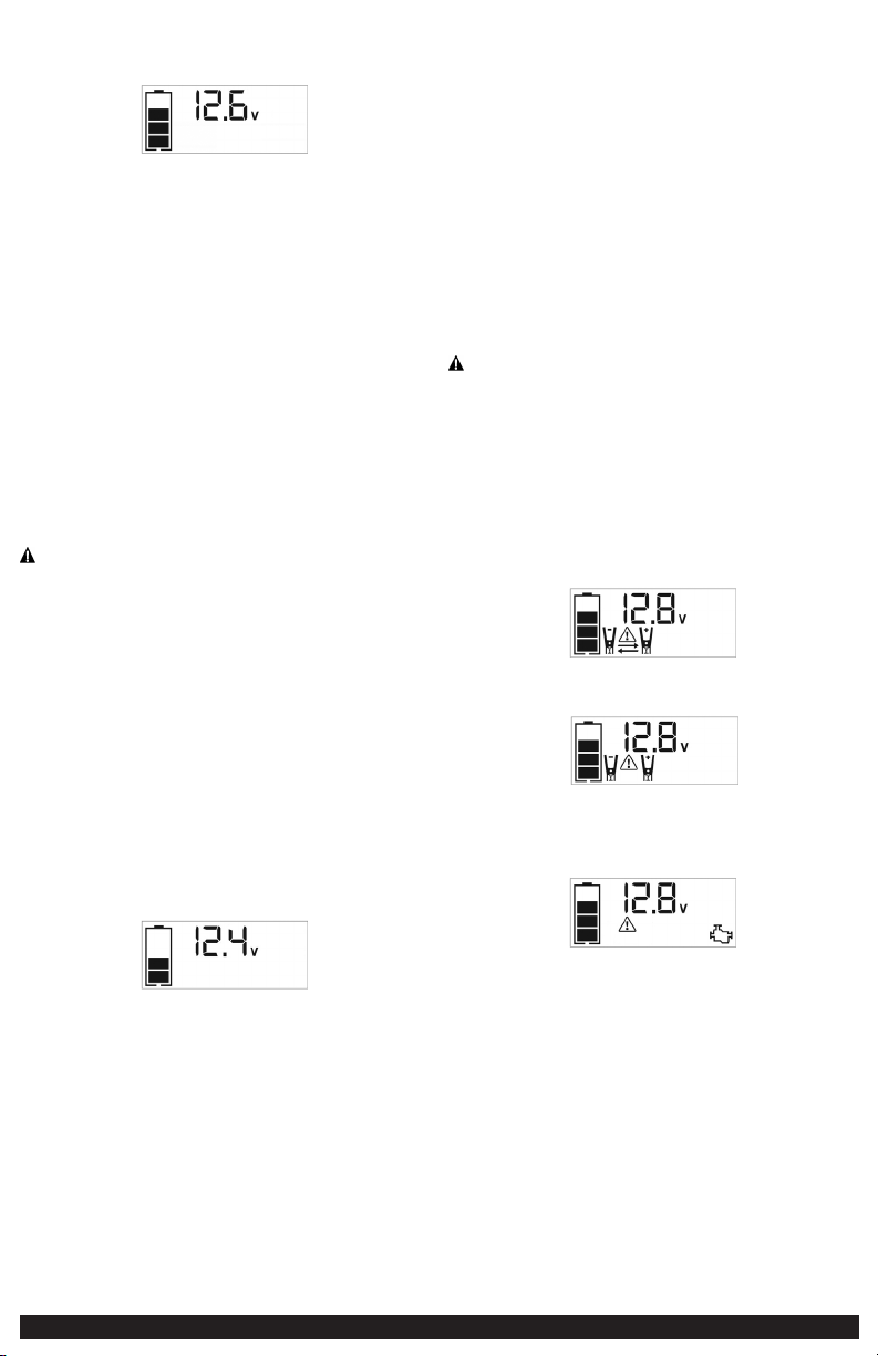
16 17
VIENDO EL ESTADO DE LA BATERÍA
El icono de estado de la batería y el indicador del voltaje de la batería indican el
nivel de carga como sigue:
• Si el nivel de carga de la batería está a plena capacidad, cuatro barras sólidas se
muestran.
• Si la batería está parcialmente cargada, dos o tres barras sólidas se mostrarán.
• Si la batería está casi vacía, una barra sólida se vea. La unidad debe ser cargada
en este momento.
• Si la batería está completamente vacía, el icono de la batería muestra cuatro
barras vacías. La unidad TIENE QUE SER cargado en este momento o protección
integrada de baja tensión de la unidad se activará. El icono de estado de la batería
vacía parpadeará para un corto período de tiempo antes de apagado automático.
La unidad no funcionará hasta que la batería es recargada.
CARGAR/RECARGAR
Esta unidad se entrega en un estado parcialmente cargado - usted debe cargarlo
completamente antes de usarlo para la primera vez. La carga inicial de la CA debe ser
por 40 horas o hasta que el icono de estado de la batería muestra 4 barras sólidas.
Las baterías de plomo-ácido requieren mantenimiento de rutina para asegurar
una carga completa y una mayor duración de la batería. Todas las baterías pierden
energía por descarga espontánea, se descargan con el paso del tiempo, y con mayor
rapidez cuando están a temperaturas más altas. Por lo tanto, las baterías necesitan
ser cargadas periódicamente para reemplazar la energía perdida por descarga
espontánea. Cuando la unidad no se usa, fabricante recomienda que se debe ser
recargada la batería al menos cada 30 días y después de cada uso.
Si no se mantiene la batería cargada puede causar daños permanentes y resultar
en un pobre rendimiento de arranque.
NOTAS IMPORTANTE:
• Recargar la batería luego de cada uso prolongará la vida de la batería; las
descargas importantes frecuentes entre recargas o el cargarla en exceso reducirán
la duración de la batería.
• Cerciórese de que el resto de las funciones de unidad estén apagadas durante la
recarga, pues ésta puede retardar el proceso de recarga.
• Si usted sabe que la unidad se descarga, pero el icono de la batería muestra cuatro
barras sólidas, como si la unidad está totalmente cargada cuando se conecta a una
fuente de alimentación de carga, esto puede ser debido a la batería interna que
tiene una alta impedancia. El fabricante sugiere salir de la unidad de carga por un
período de 40 horas usando el cargador de CA incorporado antes de su uso.
Cargar/recargar con el cargador 120V CA incorporado y el
cable de extensión CA (no incluido)
1. Levante la cubierta protectora del cargador incorporado 120 voltios CA
(consulte la sección “Características” para localizar). Conecte un cable de
extensión de la unidad. Conecte el otro extremo del cable a una toma de
corriente CA estándar de 120 voltios. Cuando la unidad esté bien conectado a
una fuente de alimentación de CA, la pantalla LCD mostrará siguiento:
Las barras en el icono de estado de la batería representan el nivel de carga de
la batería interna de la unidad. Las barras en el icono de estado de la batería
cambiará de vacía a sólido (de abajo a arriba) varias veces para indicar que la
unidad se está cargando. La luz de fondo se encenderá durante 10 segundos
(solamente).
2. Carga por aproximadamente 40 horas o hasta que el icono de la batería
demuestra 4 barras sólidas.
3. Cuando la carga esté completa, desconecte el cable de extensión de CA del
tomacorriente de CA y, a continuación, desconecte el cable de la unidad.
PUENTE AUXILIAR DE ARRANQUE
Esta unidad se equipa de un botón del puente auxiliar de arranque que permita
que fluya la energía solamente cuando las conexiones apropiadas se hacen a la
batería y al marco.
A. Para los sistemas con negativo a tierra, conecte la pinza del positivo (ROJA)
al borne sin conexión a tierra de la batería y la pinza del negativo (NEGRA)
al bastidor del vehículo o al bloque del motor, lejos de la batería. No conecte
la pinza al carburador, las cañerías de combustible o a las piezas de chapa de
la carrocería. Conecte a una pieza de metal sólida del bastidor o del bloque
del motor.
B. Para los sistemas con positivo a tierra, conecte la pinza del negativo (NEGRA)
al borne sin conexión a tierra negativo de la batería y la pinza del positivo
(ROJA) al bastidor del vehículo o al bloque del motor, lejos de la batería. No
conecte la pinza al carburador, las cañerías de combustible o a las piezas de
chapa de la carrocería. Conecte a una pieza de metal sólida del bastidor o del
bloque del motor.
IMPORTANTE: Asegúrese de que el botón de alimentación del compresor se ha
apagado antes de intentar utilizar la unidad como un puente auxiliar de arranque.
ADVERTENCIA – PARA REDUCIR EL RIESGO DE LESIONES O DAÑO A LA
PROPIEDAD:
• Siga todas las instrucciones de seguridad encontradas en la sección de las
“Instrucciones de seguridad específicas para auxiliares de arranque” de este
manual de la instrucción.
• Nunca toque entre sí las pinzas roja y negra de la batería: esto puede provocar
chispas peligrosas, arco eléctrico o explosión.
• Si las pinzas están conectados incorrectamente con respecto a la polaridad, la
unidad sonará una alarma continua hasta que las pinzas estén desconectados. La
pantalla LCD mostrará el icono de estado de la batería, el indicador del voltaje
de la batería y los iconos de pinzas. Los signos “+” y “–” por encima de los iconos
de pinzas, los iconos de polaridad inversa y el icono de la alarma parpadeará. La
pantalla LCD retroiluminada mostrará siguiento:
• Si las pinzas rojas y negras se tocan entre sí, la unidad emitirá una alarma continua
de dos segundos cada diez segundos hasta que las pinzas estén separadas. La
pantalla LCD retroiluminada mostrará lo siguiente:
El ícono de estado de la batería y el indicador de voltaje de la batería se
iluminarán. El icono de alarma, los iconos de pinzas y los signos “+” y “–”
parpadearán.
• Si la unidad se sobrecalienta durante el proceso de arranque, la protección térmica
se activará y la pantalla LCD retroiluminada mostrará lo siguiente:
El ícono de estado de la batería y el indicador de voltaje de la batería se
iluminarán. El ícono de alarma y el icono del puente auxiliar de arranque
parpadearán.
• Siempre desconecte primero el cable del puente del negativo (negro) y luego el
cable del puente del positivo (rojo), excepto para los sistemas con positivo a tierra.
Procedimiento
Tome las medidas siguientes, observando todas las precauciones y advertencias en la
sección de las “instrucciones de seguridad importantes” en el frente de este manual.
1. Apague la ignición del vehículo y todos los accesorios (radio, aire
acondicionado, luces, cargadores de teléfono celular conectados, etc.). Ubique
el vehículo en “estacionar” y coloque el freno de emergencia.
2. Asegúrese de que el botón de alimentación del puente auxiliar de arranque
está apagado.
3. Retire las pinzas del puente de sus respectivas lengüetas. Conecte primero la
pinza roja, luego la pinza negra.
4. Procedimiento para arrancar mediante puente un sistema con negativo a tierra
(el terminal de la batería está conectado al bastidor) (lo más común):
4a. Conecte la pinza ROJA del positivo (+) al terminal del positivo de la
batería del vehículo.
4b. Conecte la pinza NEGRA del negativo (–) al bastidor o a un componente
metálico no móvil y sólido, o una parte de la carrocería. Nunca fije la
pinza directamente al terminal del negativo de la batería o a una pieza
móvil. Refiera al manual del dueño del automóvil.
5. Procedimiento para arrancar sistemas con positivo a tierra:
Nota: En el caso poco habitual de que el vehículo que se debe arrancar tenga un sistema de positivo
a tierra (el terminal positivo de la batería está conectado al bastidor), reemplace los pasos 4a y
4b anteriores con los pasos 5a y 5b, luego continúe con el paso 6.
5a. Conecte la pinza NEGRA del negativo (–) al terminal del negativo de la
batería del vehículo.
5b. Conecte la pinza ROJA del positivo (+) al bastidor del vehículo o a un
componente metálico no móvil y sólido, o una parte de la carrocería.
Nunca fije la pinza directamente al terminal del positivo de la batería o a
una pieza móvil. Refiera al manual del dueño del automóvil.
6. Cuando las pinzas están conectadas correctamente, la pantalla LCD
retroiluminada demostrará:
El icono de estado de la batería, el indicador del voltaje de la batería, los
iconos de pinzas y los signos “+” y “–” se iluminan sólidamente.
7. Encienda el botón de alimentación del puente auxiliar de arranque. La pantalla
LCD retroiluminada mostrará lo siguiento para indicar que la unidad está lista
para arrancar:
El icono de estado de la batería, el indicador del voltaje de la batería, los iconos
de pinzas y los signos “+” y “–” se iluminan sólidamente. El icono del puente
auxiliar de arranque se parpadeará para indicar que las pinzas están conectadas
correctamente.
Nota: Si se ha presionado el botón de alimentación del puente auxiliar de arranque para encender
el arrancador de arranque y las pinzas no están conectadas a la batería, la pantalla LCD
retroiluminada mostrará lo siguiento:
La unidad permanece encendida luego muestra el icono de estado de la batería y el indicador
de voltaje de la batería durante 10 segundos antes apagado automático. El fabricante
sugiere que siempre se conecte correctamente a una batería antes de encender el botón de
alimentación del puente auxiliar de arranque.
8. Encienda la ignición y acelere el motor en etapas de 5 a 6 segundos hasta que
arranque. La pantalla LCD retroiluminada mostrará siguiento:
9. El icono de estado de la batería, el indicador del voltaje de la batería, el icono
del puente auxiliar de arranque, los iconos de pinzas y los signos “+” y “–” se
iluminan sólidamente para indicar que la unidad está de iniciar la batería.
10. Coloque el interruptor de encendido del puente auxiliar de arranque en la
posición de apagado (off) nuevamente.
11. Desconecte la pinza negativo (–) del motor o bastidor primero y luego
desconecte la pinza positivo (+) de la batería.
IMPORTANTE: Siempre apague la unidad cuando no está en uso. Vuelva a cargar la
unidad completamente después de cada uso.
PRECAUCIÓN – PARA REDUCIR EL RIESGO DE DAÑO A LA PROPIEDAD:
• Los vehículos que tienen sistemas computarizados incorporados pueden resultar
dañados si la batería del vehículo se arranca mediante puente. Antes de arrancar
mediante puente este tipo de vehículo, lea el manual del vehículo para confirmar
que se aconseja ayuda externa para arrancar.
• El exceso de revoluciones del motor puede dañar el mecanismo de arranque
del vehículo. Si el motor no arranca después de la cantidad recomendada de
intentos, abandone el procedimiento de arranque mediante puente y busque otros
problemas que puedan ser solucionados.
• Si el vehículo no arranca, apague la ignición, coloque el botón de alimentación del
puente auxiliar de arranque en la posición de apagado, desconecte los conductores
del puente auxiliar de arranque y comuníquese con un técnico calificado para
investigar por qué no arrancó el motor.
LUZ ZONAL
La luz del área está controlada por el botón de encendido de la luz del área en el
panel de control (consulte la sección “Características” para localizarlo).
1. Presione el botón de encendido de la luz del área una vez para encender la luz.
2. Presione el botón de encendido de la luz del área nuevamente para apagar la
luz del área.
Cuando se presione el botón de encendido de la luz de área para encenderlo,
sonará un pitido. La pantalla LCD retroiluminada se encenderá durante 10 segundos
(solamente) y luego mostrará continuamente el icono de estado de la batería y el
indicador de voltaje de la batería.
Compruebe periódicamente el estado de la batería de la unidad en la pantalla
del LCD. Cuatro barras sólidas en el icono de la batería indican una batería llena.
Cuando el nivel de la batería está casi vacía con sólo una única de barras sólidas o
cuatro bares vacíos, la unidad debe ser recargada en este momento o protección
integrada de baja tensión de la unidad se activará. El icono de estado de la batería
vacía parpadeará para un corto período de tiempo antes de apagado automático.
IMPORTANTE: Cerciórese de que la luz de área y la unidad estén dadas vuelta de
cuando se está recargando o se está almacenando la unidad.
TOMACORRIENTE DE 120V CA
Consumo de corriente real versus calificado del equipo
La mayoría de las herramientas eléctricas, los aparatos, los dispositivos electrónicos
y los equipos visuales/de audio poseen etiquetas que indican el consumo de energía
en amperios o vatios. Asegúrese de que el consumo de energía del artículo que
desee operar sea menor a 500 vatios. Si el consumo de energía se clasifica en CA
de amperios, simplemente multiplique por los voltios de CA (120) para determinar
la vatiaje.
La unidad puede transportar las cargas resistivas con más facilidad. No obstante, las
cargas resistivas más grandes, como estufas o calentadores eléctricos, generalmente
requieren más potencia en vatios de la que puede suministrar la unidad en forma
continua. Las cargas inductivas, como televisores y estéreos, requieren más corriente
para funcionar que las cargas resistivas de la misma clasificación de potencia en vatios.
La forma de onda de salida del inversor
La forma de onda de la salida CA de este inversor se conoce como una onda
senoidal modificada. Es una forma de onda escalonada que posee características
similares a la forma de onda senoidal de la electricidad. Este tipo de forma de onda
es adecuado para la mayoría de las cargas CA, incluidas las fuentes de energía
por conmutación y lineales utilizadas en equipos electrónicos, transformadores y
motores pequeños.
Características de protección
El inversor supervisa las siguientes condiciones:
Voltaje interno bajo de la
batería
El inversor cerrará automáticamente cuando las
caídas de voltaje de la batería demasiado bajas,
como esto pueden dañar la batería.
Alto voltaje interno de la
batería
El inversor cerrará automáticamente cuando el
voltaje de la batería es demasiado alto, pues éste
puede dañar la unidad.
Protección de apagado
térmico
El inversor se apagará automáticamente cuando
la unidad se sobrecaliente.
Protección contra
cortocircuitos o sobrecargas
El inversor se apagará automáticamente en
presencia de un cortocircuito o sobrecargas.
NOTAS IMPORTANTE:
El tomacorriente de CA proporciona un consumo total de energía de 500W.
Cuando el tomacorriente CA están en uso, la unidad vigilará para las siguientes
condiciones de fallo: batería alta o baja, fallo térmico, fallo en la tensión de
la batería, sobrecarga y cortocircuito (consulte la sección “Características de
protección”).
1. Si existe un fallo de baja voltaje de la batería interna en
el tomacorriente CA
,
el
tomacorriente CA
se apagará automáticamente y la pantalla LCD retroiluminada
se mostrará lo siguiento hasta que se corrija la falla:
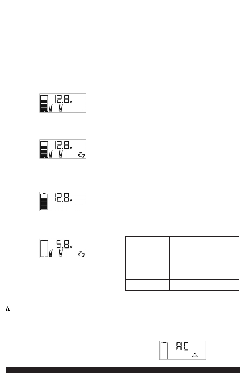
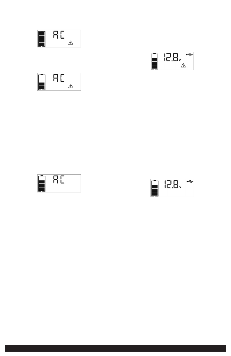
18 19
La pantalla digital mostrará “AC”;
el icono de estado de la batería VACÍO y el
icono de fallo en la pantalla LCD parpadearán.
2. Si existe un fallo de alta voltaje de la batería interna en
el tomacorriente CA
,
el
tomacorriente CA
se apagará automáticamente y la pantalla LCD retroiluminada
se mostrará lo siguiento hasta que se corrija la falla:
La pantalla digital mostrará “AC”;
el icono de estado de la batería LLENA y el
icono de fallo en la pantalla LCD parpadearán.
3. Si existe un fallo térmico, cortocircuitos o sobrecargas en
el tomacorriente CA
,
el
tomacorriente CA
se apagará automáticamente y la pantalla LCD retroiluminada
se mostrará lo siguiento hasta que se corrija la falla:
El icono de estado de la batería se encenderá de forma sólida; y “AC” en la
pantalla digital y el icono de fallo en la pantalla LCD parpadearán.
En caso de que se produzca alguna de las condiciones de falla anteriores:
1. Desconecta el dispositivo de la unidad.
2. Pulse el botón de alimentación de CA para desactivar el tomacorriente CA.
3. Asegúrese de que la unidad no necesita ser recargada.
4. Deje que la unidad se enfríe durante varios minutos.
5. Asegúrese de que la calificación del aparato conectado a la unidad es de 500
vatios o más bajas y que el cable del aparato y el enchufe no estén dañados.
6. Asegurar que haya suficiente ventilación alrededor de la unidad antes de
continuar.
Usando el tomacorriente de 120 voltios CA
El tomacorriente de CA de 120 voltios se encuentra en la parte frontal de la unidad.
El tomacorriente admite un consumo de energía máximo de 500 vatios.
1. Pulse el botón de alimentación de CA para encender el tomacorriente de 120
voltios CA. Sonará un pitido y la pantalla LCD mostrará el siguiente:
El icono de estado de la batería y la pantalla digital muestra “AC”, que indica
la toma de CA está listo para usar.
2. Inserte el enchufe de la CA de 120 voltios del aparato en una del tomacorriente
de CA.
3. Encender el aparato y operar como de costumbre.
Nota: Asegúrese de que la potencia del equipo conectado a la toma de corriente de 120V CA no
exceda los 500 vatios continuos.
4. Presione el botón de alimentación de CA nuevamente para apagar el
tomacorriente de 120V CA.
Compruebe periódicamente el estado de la batería de la unidad en la pantalla
del LCD. Cuatro barras sólidas en el icono de la batería indican una batería llena.
Cuando el nivel de la batería está casi vacía con sólo una única de barras sólidas o 4
bares vacíos, la unidad debe ser recargada en este momento o protección integrada
de baja tensión de la unidad se activará. El icono de estado de la batería vacía
parpadeará para un corto período de tiempo antes de apagado automático.
IMPORTANTE: Asegúrese de que el tomacorriente de CA esté apagada cuando la
unidad se está recargando o almacenando.
PUERTOS USB
El botón de alimentación USB y los tres puertos USB están situados en la parte
delantera de la unidad (consulte la sección “Características” para localizar).
NOTAS IMPORTANTES:
1. Los tres puertos USB proporcionan 3.1A (5V) cada uno.
2. Cuando los puertos USB están en uso, la unidad vigilará todos los puertos
USB para las siguientes condiciones de fallo: fallo en la tensión de la batería
baja, sobrecarga y cortocircuito. En cualquiera de estos casos, la pantalla LCD
retroiluminado mostrará continuamente lo siguiento:
El icono del falla parpadeará. Los puertos USB con alimentación se apagará
automáticamente. Si esto ocurre:
2a. Desconecte el dispositivo USB y pulse el botón de alimentación USB de
nuevo para desactivar los puertos USB inmediatamente.
2b. Asegúrese de que la unidad no necesita ser recargada.
2c. Deje que la unidad se enfríe durante varios minutos antes de intentar
usar los puertos USB de nuevo.
2d. Si vuelve a producirse un error, asegúrese de que la consumo total del
dispositivo USB conectado al puerto USB no supere los 3.1A (5V).
2e. Si un dispositivo USB individuo está dentro de las especificaciones
y se produce el fallo, tener el dispositivo USB comprobado para
funcionamiento defectuoso y no seguir utilizándolo con estos puertos
USB.
3. Los puertos USB de esta unidad no soportan la comunicación de datos. Sólo
proporcionan alimentación a dispositivos USB externos. Los puertos USB
proporcionan un total de 3.1A (5V) cada uno.
4. Algunos dispositivos electrónicos con conexión USB no funcionará con esta
unidad.
Usando los puertos USB
1. Pulse el botón de alimentación USB para activar los puertos USB. Sonará un
pitido. La luz de fondo se encenderá durante 10 segundos (solamente). La
pantalla LCD retroiluminada mostrará continuamente lo siguiente:
El icono de estado de la batería y el indicador del voltaje de la batería se
iluminará de sólidos, así como el icono USB, indicando los puertos USB están
listos para usar.
2. Conecte el dispositivo USB en el puerto (los puertos) USB y funciona
normalmente.
3. Pulse el botón de alimentación USB de nuevo para desactivar los puertos USB.
Compruebe periódicamente el estado de la batería de la unidad en la pantalla
del LCD. Cuatro barras sólidas en el icono de la batería indican una batería llena.
Cuando el nivel de la batería está casi vacía con sólo una única de barras sólidas o 4
bares vacíos, la unidad debe ser recargada en este momento o protección integrada
de baja tensión de la unidad se activará. El icono de estado de la batería vacía
parpadeará para un corto período de tiempo antes de apagado automático.
IMPORTANTE: Asegúrese de que los puertos USB estén apagados cuando la unidad
se recarga o almacenado.
COMPRESOR PORTÁTIL
El compresor incorporado de CC de 12 voltios es el compresor de última generación
para los neumáticos de todos los vehículos, remolques y artículos inflables para
recreación. Un adaptador de la boquilla se suministra que los tornillos en el
extremo de la boquilla Sure Fit
®
en el extremo libre de la manguera del compresor.
La manguera del compresor con montaje de los neumáticos se almacena en el
compartimiento de almacenamiento (consulte la sección “Características” para
localizar). El botón de alimentación del compresor y botones para aumentar (+) y
disminuir (–) la presión del compresor están localizados en el panel de control en la
parte frontal de la unidad.
Antes de continuar, compruebe el estado de la batería de la unidad en la pantalla
LCD. Cuatro barras sólidas en el icono de la batería indica una batería llena. Cuando
el nivel de la batería está casi vacío con sólo una barra sólida, la unidad se debe
recargar antes de usar o protección integrada de baja tensión de la unidad se
activará. El icono de estado de la batería vacía parpadeará para un corto período de
tiempo antes de apagado automático.
El compresor es capaz de inflar hasta 120 libras por la presión de la pulgada
cuadrada (PSI). El compresor puede funcionar lo suficiente para llenar hasta 3
neumáticos de medida promedio antes de tener que recargar la batería. Vuelva a
colocar la manguera en el compartimiento de almacenamiento después del uso.
IMPORTANTE: Asegúrese de que el interruptor del puente auxiliar de arranque se ha
apagado antes de intentar utilizar la unidad como un compresor.
ADVERTENCIA – Para reducir el riesgo de lesiones graves o daños
materiales: Siga todas las instrucciones de seguridad encontradas en la sección de
las “instrucciones de seguridad específicas para compresores” de este manual de la
instrucción.
PRECAUCIÓN – Para reducir el riesgo de daños materiales: Cuando el
compresor es operado a un PSI baja, la unidad puede comenzar en baja y acelerar
gradualmente. Cuando el compresor es operado a más alto PSIs, la unidad puede
funcionar normalmente durante varios minutos, luego decelerar durante unos
minutos antes de volver a la operación normal. Esta característica protege la unidad
del sobrecalentamiento durante uso normal. En cualquier caso, no haga funcionar
el compresor de forma continua durante más de 10 minutos, ya que se puede
sobrecalentar. Esto podría dañar el compresor. Si el compresor debe funcionar
durante más tiempo: cada 10 minutos, pulse el botón de encendido para encender
compresor del compresor, a continuación, reiniciar después de un periodo de
enfriamiento de aproximadamente 30 minutos.
En cualquier caso, el compresor se apagará automáticamente después de funcionar
continuamente durante 10 minutos.
Cómo inflar neumáticos o productos con vástagos de
válvulas
1. Atornille la boquilla Sure Fit
®
en el vástago de la válvula. No apriete demasiado.
2. Presione el botón de alimentación del compresor. Sonará un pitido y la pantalla
LCD retroiluminada demostrará siguiento:
El icono del compresor se encenderá y la pantalla LCD retroiluminada mostrará
alternativamente el preajustado valor psi que parpadea (el último valor
introducido por los botones de control de presión del compresor) y la actual psi
presión del artículo al ser inflado (que se ilumina sólido).
3. Presione los botones “+” y “–” de control de presión para ajustar la presión
deseada entre una gama de valores predefinidos (entre 1 y 120), que se
mostrará en la pantalla LCD retroiluminada. La unidad emitirá un pitido cada
vez que pulsa los botones (sosteniendo el botón acelera la selección de valor
hacia arriba o hacia abajo). Una vez que se ha entrado en la presión deseada,
suelte el botón y la pantalla LCD retroiluminada intermitente mostrará la nueva
presión seleccionado, de la siguiente manera:
El valor seleccionado nuevo se guarda en la memoria de la unidad hasta que se
resetea manualmente.
4. Presione el botón de alimentación del compresor una vez más para comenzar a
inflar. El icono del compresor parpadea y la pantalla digital sólo se mostrará el
valor de la presión actual (que se ilumina sólido) para indicar que el compresor
se activa. Supervise la presión sobre la pantalla del LCD.
NOTA IMPORTANTE: Para interrumpir durante el inflado, pulse el botón de
alimentación del compresor una vez más.
5. Cuando se alcance la presión predefinido deseada, el compresor parará
automáticamente.
6. Pulse el botón de alimentación del compresor para apagar la unidad.
7. Desatornille y retire el conector de la boquilla Sure Fit
®
desde el vástago de
la válvula.
8. Permita que la unidad se refresque, después recargue antes de almacenarla.
9. Almacene la manguera del compresor y la boquilla Sure Fit
®
en el
compartimiento de almacenamiento
.
Cómo inflar otros artículos inflables sin vástago de válvula
El inflado de otros artículos requiere el uso del adaptador de la boquilla.
1. Atornille el adaptador dentro la boquilla Sure Fit
®
. No apriete demasiado.
2. Inserte el adaptador en el artículo a ser inflado.
3. Siga los pasos 2 a 4 de la sección “Cómo inflar neumáticos o productos con
vástagos de válvulas.”
NOTA IMPORTANTE: Los artículos pequeños como las pelotas de voleibol,
fútbol, etc. se inflan muy rápidamente. No infle demasiado.
4. Cuando se alcanza la presión deseada, el compresor se parará automáticamente.
Pulse el botón de alimentación del compresor para apagar la unidad.
5. Desconecte el adaptador del artículo inflado.
6. Desatornille y retire el adaptador dla boquilla Sure Fit
®
.
7. Permita que la unidad se enfríe antes de almacenarla.
8. Almacene la manguera del compresor, la boquilla Sure Fit
®
y el adaptador de la
boquilla en el compartimiento de almacenamiento cuando no está en uso.
CUIDADO Y MANTENIMIENTO
Con el tiempo, todas las baterías pierden energía debido a la descarga automática y
con mayor rapidez en ambientes con temperaturas elevadas. Cuando la unidad no
esté en uso, recomendamos cargar la batería al menos cada 30 días.
No sumerja este reflector en agua. Si la unidad se ensucia, limpie las superficies
exteriores con cuidado. Utilize una tela suave humedecida con una mezcla diluida
de agua y detergente.
No hay ningún usuario-sustituibles piezas. Periódicamente inspeccione la condición
de adaptadores, conectores y alambres. Contacto fabricante para sustituir los
componentes que han pasado a ser gastado o rotas.
Batería
Veuillez noter que la batterie est conçue pour durer toute la durée de vie de l’unité
et n’est pas remplaçable, amovible ou réparable. La durée de vie utile dépend de
certains facteurs, y compris, mais sans s’y limiter, du nombre de cycles de recharge
et de l’entretien et de la maintenance appropriés de la batterie effectués par
l’utilisateur final. Pour obtenir tout renseignement supplémentaire, communiquer
avec le fabricant.
ELIMINACIÓN SÛRE DE LA BATERÍA
Contiene una batería de plomo ácido, que se deben desechar de
manera adecuada. Reciclar es necesario. El incumplimiento de
regulaciones locales, estatales y federales, puede resultar en multas
o prisión.
Por favor recicle.
ADVERTENCIAS:
• No deseche la batería en el fuego ya que puede ocasionar una explosión.
• Antes de desechar la batería, proteja las terminales descubiertas con cinta eléctrica
para trabajos pesados. De esta manera previene cortos circuitos (los cortos circuitos
pueden ocasionar lesiones e incendios).
• No exponga la batería al fuego o al calor extremo ya que puede explotar.
DETECCIÓN DE PROBLEMAS
La unidad no cargará
• Cerciórese de que el botón de alimentación de CA esté apagado.
• Cerciórese de que una cuerda de extensión del calibrador correcto esté conectada
correctamente con la unidad y un enchufe de funcionamiento de la CA.
La unidad no puede arranque del motor
• Asegúrese de que la unidad no esté funcionando en el modo compresor.
• Asegúrese de que el botón del arrancador de la unidad está en la posición
encendido.
• Asegúrese de que se han realizado las conexiones de los cables con la polaridad
correcta.
• La unidad puede estar sobrecalentada debido al exceso de arranque del motor.
Asegúrese de que todas las funciones de la unidad estén apagadas y permita que
la unidad se enfríe antes de reanudar la operación.
• Compruebe que la unidad tiene una carga completa. Recargue la unidad en caso
de necesidad.
El enchufe de 120 voltios CA no accionará la aplicación
• Asegúrese de que la unidad no esté en funcionamiento en el modo de arranque
del motor.
• Cerciórese de que el botón de alimentación de CA esté en la posición de trabajo.
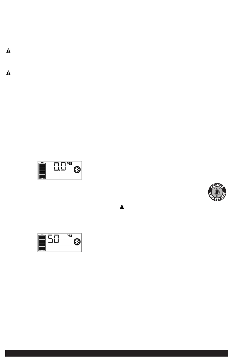

120
PORTABLE POWER STATION
INSTRUCTION MANUAL
FUENTE DE ENERGÍA PORTÁTIL
MANUAL DE INSTRUCCIÓN
SAVE THIS INSTRUCTION MANUAL FOR FUTURE REFERENCE.
CONSERVE ESTE MANUAL PARA FUTURAS CONSULTAS.
© 2021 Baccus Global LLC
Boca Raton, FL 33487
1-877-571-2391
J5CPD
English page 5
Español pagina 12
BC
• Asegúrese de haber seguido todos los pasos de la sección “120 tomacorrientes
de CA” con cuidado. Consulte las notas importantes incluidas en esa sección que
explican problemas y soluciones comunes.
• Asegúrese de que el aparato está alimentado no extrae más de 500 vatios.
• Refiera a las notas importantes incluidas en esa sección que explican problemas
comunes y soluciones.
• Compruebe que la unidad tiene una carga completa. Recargue la unidad en caso
de necesidad.
El puerto de la energía del USB no accionará la aplicación
• Asegúrese de que el botón de encendido/apagado del puerto de carga USB se ha
presionado para activar los puertos USB.
• Si existe una condición de falla en cualquiera de los puertos USB, el ícono de
falla en la pantalla LCD parpadeará. Consulte las notas importantes en la sección
“Puertos USB” para solucionar cualquier fallo.
• Asegúrese de que la extracción total de todos los dispositivos USB conectados a los
puertos USB izquierdos no exceda los 3.1A (5V).
• Algunos productos electrónicos de uso doméstico alimentados por USB no
funcionan con esta puerto de carga / potencia del USB. Compruebe el manual del
dispositivo electrónico correspondiente para confirmar que se puede utilizar con
este tipo de puerto de carga / potencia del USB.
• Compruebe que la unidad tiene una carga completa. Recargue la unidad en caso
de necesidad.
La luz de área LED no enciende
• Cerciórese de que el botón de encendido de la luz de área LED se ha presionado
para activar la luz de área LED.
• Compruebe que la unidad tiene una carga completa. Recargue la unidad en caso
de necesidad.
El compresor portátil no inflará
• Asegúrese de que la unidad no esté funcionando en el modo de inicio de salto.
• Asegúrese de que el botón de encendido del compresor se ha presionado para
activar el compresor.
• Asegúrese de que el conector de la boquilla Sure Fit
®
está firmemente atornillada
al vástago de válvula cuando se intenta inflar los neumáticos; o que el adaptador
de la boquilla se atornilla firmemente en el conector de la boquilla Sure Fit
®
y está
insertado correctamente en el elemento a ser inflado en todos los otros objetos
inflables.
• El compresor puede sobrecalentarse. Pulse el botón de encendido del compresor
para apagar el compresor. Reinicie después de un período de enfriamiento de 30
minutos aproximadamente.
• Compruebe que la unidad tiene una carga completa. Recargue la unidad en caso
de necesidad.
ACCESORIOS
Accesorios recomendados para uso con esta unidad puede ser disponibles a través
del fabricante. Si necesita ayuda con respecto a los accesorios, por favor póngase en
contacto con el fabricante al 1-877-571-2391.
El uso de cualquier accesorio no recomendado para el uso con esta unidad
podía ser peligroso.
INFORMACIÓN DE SERVICIO
Si usted necesita asesoramiento técnico, reparación, o partes genuinas del
fabricante, póngase en contacto con el fabricante al 1-877-571-2391.
UN AÑO DE GARANTÍA LIMITADA
El fabricante garantiza este producto contra defectos de materiales y mano de obra
durante un período de UN (1) AÑO a partir de la fecha de compra del producto
por el comprador usuario final (“Período de Garantía”). Si hay un defecto y una
reclamación válida se recibe dentro del período de garantía, el producto defectuoso
puede ser reemplazado o reparado en el las siguientes maneras: (1) Devuelva el
producto al fabricante para reparación o reemplazo, a opción del fabricante. La
prueba de compra puede ser requerida por el fabricante. (2) Devuelva el producto
a la tienda donde el producto fue comprado para un intercambio (siempre y
cuando se trate de un minorista participante). Devoluciones al minorista deben
hacerse dentro del plazo de póliza de devoluciones del minorista para intercambios
solamente (por lo general 30 a 90 días después de la fecha de compra). La prueba
de compra puede ser requerida por el minorista. Por favor consulte la póliza de
devoluciones del minorista sobre devoluciones que están fuera del plazo establecido
para intercambios.
Esta garantía no se aplica a los accesorios, bombillos, fusibles y baterías; defectos a
consecuencias de desgaste normal; accidentes; daños y perjuicios sufridos durante el
envío y manejo, alteraciones, reparaciones o uso no autorizado, negligencia, abuso,
y si no se siguen instrucciones para el cuidado y mantenimiento del producto.
Esta garantía le otorga al comprador usuario final, derechos legales específicos y
usted puede tener otros derechos que varían de estado a estado o de provincia a
provincia. Este producto no está diseñado para uso comercial.
Asegúrese de registrar su producto en https://www.baccusglobal.com/registration
para recibir información importante sobre el producto, promociones y ofertas
especiales, y más.
ESPECIFICACIONES
Amperios de impulso: 12V CC, 1200A pico batería,
600A instantánea
Tipo de batería: De plomo sin necesidad de mantenimiento,
sellada, 12V CC
Entrada de CA: 120V CA, 60Hz, 13W
Luz de área: 1 LED blanco
Puertos USB: 3.1A max., 5V CC
Tomacorriente de la CA: 120V CA, 60Hz, 500W continuo
Presión máxima del aparato
para compresor: 120 PSI
Sure Fit
®
es una marca registrada de los EE. UU. Propiedad de Baccus Global, LLC.
STANLEY
®
Y EL LOGOTIPO DE STANLEY
®
SON
MARCAS REGISTRADAS DE STANLEY BLACK + DECKER
INC. O DE UNA DE SUS FILIALES
Y SE UTILIZAN BAJO LICENCIA.
Importados por Baccus Global LLC,
621 NW 53rd St., Suite 450, Boca Raton, FL 33487
www.baccusglobal.com 1-877-571-2391
RD090921
