Loading ...
Loading ...
Loading ...
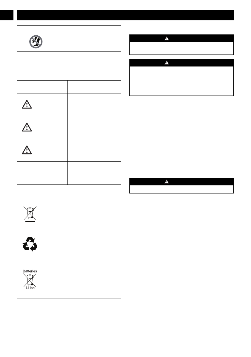
Symbol Explanation
Keep hands and feet away from the
cleaning deck while the pressure
washer is running.
7 RISK LEVELS
The following signal words and meanings are intended to
explain the levels of risk associated with this product.
SYM-
BOL
SIGNAL MEANING
DANGER Indicates an imminently haz-
ardous situation, which, if not
avoided, will result in death
or serious injury.
WARNING Indicates a potentially hazard-
ous situation, which, if not
avoided, could result in death
or serious injury.
CAUTION Indicates a potentially hazard-
ous situation, which, if not
avoided, may result in minor
or moderate injury.
CAUTION (Without Safety Alert Sym-
bol) Indicates a situation that
may result in property dam-
age.
8 RECYCLE
Separate collection. You must not discard
with usual household waste. If it is necessa-
ry to replace the machine, or if it is no more
use to you, do not discard it with household
waste.
Separate collection of used machine and
packaging let you recycle materials and use
them again. Use of the recycled materials
helps prevent environmental pollution and
decreases the requirements for raw materi-
als.
At the end of their useful life, discard batter-
ies with a precaution for our environment.
The battery contains material that is danger-
ous to you and the environment. You must
remove and discard these materials separate-
ly at a location that accepts lithium-ion bat-
teries.
9 INSTALLATION
9.1 UNPACK THE MACHINE
WARNING
Make sure that you correctly assemble the machine before
use.
WARNING
• If the parts have damage, do not use the machine.
• If you do not have all the parts, do not operate the
machine.
• If the parts are damaged or missing, speak to the service
center.
1. Open the package.
2. Read the documentation in the box.
3. Remove all the unassembled parts from the box.
4. Remove the machine from the box.
5. Discard the box and package in compliance with local
regulations.
9.2 INSTALL THE SPRAY WAND
Figure 2.
1. Push the end of the spray wand into the gun handle.
2. Turn the spray wand clockwise until the tabs lock into
position.
WARNING
Make sure that the connection has no leakage.
9.3 INSTALL THE GUN HOLDER
Figure 3.
1. Engage the gun holder into the slot until it locks into its
tabs.
9.4 INSTALL THE WATER INLET
CONNECTOR
Figure 4.
1. Install the water inlet connector onto the water inlet
coupler.
2. Turn the water inlet connector clockwise until it is tight.
9.5 INSTALL THE FRONT PEDESTAL
Figure 4.
1. Aligh the screw sleeves of the pedestal with the screw
holes.
2. Push the screws through the screw sleeves and tighten
them.
4
English
EN
Loading ...
Loading ...
Loading ...