Loading ...
Loading ...
Loading ...
31
REMOTE CONTROL OPERATION
FUNCTIONS:
INSTALLATION INSTRUCTIONS
INSTALLATION
HEARTH MOUNT
WIRING INSTRUCTIONS
• With the slide switch in the REMOTE position, the system will only
operate if the remote receiver receives commands from the transmitter.
• Upon initial use or after an extended period of no use, the ON button
may have to be pressed for up to three seconds before activating servo
motor. If the system does not respond to the transmitter on initial use,
see LEARNING TRANSMITTER TO RECEIVER.
• With the slide switch in the ON position you can manually turn ON the
system.
• With the slide in the OFF position, the system is OFF.
• It is suggested that the slide switch be placed in the OFF position if you
will be away from your home for an extended period of time.
• Placing the slide switch in the OFF position also functions as a safety
"lock out" by both turning the system OFF and rendering the transmitter
inoperative.
The remote receiver can be mounted on or near the replace hearth.
PROTECTION FROM EXTREME HEAT IS VERY IMPORTANT. Like any
piece of electronic equipment, the remote receiver should be kept away from
temperatures exceeding 130ºF inside the receiver case. Battery life is also
signicantly shortened if batteries are exposed to high temperatures.
The remote receiver can be placed on the replace hearth or under the replace,
behind the control access panel. Position where the ambient temperature inside
the receiver case does not exceed 130ºF. NOTE: Black Button is used on Hearth
Mount Applications.
Make sure the remote receiver switch is in the OFF position. For best results it is
recommended that 18 gauge stranded wires should be used to make connections
and no longer than 20-feet.
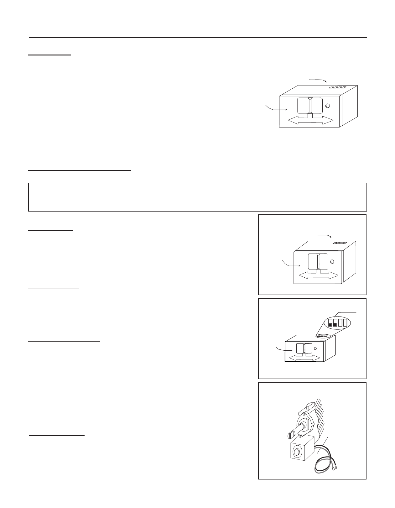
This GH03-R remote receiver is to be connected to a manual valve with a
latching ON/OFF solenoid.
Connect two 18 gauge stranded or solid wires from the remote receiver terminals
to the latching solenoid. (See gure to the right)
IMPORTANT NOTE: Operation of this control is dependent on which wire
is attached to which terminal. If operation of control does not correspond to
operating buttons on transmitter, reverse wire installation at the receiver or at the
control.
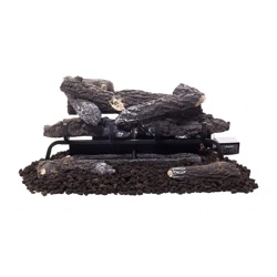
LEARN
Remote Receiver
Wire terminals
Receiver
Slide
Button
REMOTE ONOFF
LEARN
Remote Receiver
Wire terminals
Receiver
Slide
Button
REMOTE ONOFF
LEARN
Remote Receiver
Receiver
Slide
Button
PULSE MODE
Terminals
REMOTE ONOFF
WARNING
DO NOT CONNECT REMOTE RECEIVER DIRECTLY TO 110-120VAC POWER. THIS WILL BURN OUT THE RECEIVER.
FOLLOW INSTRUCTIONS FROM MANUFACTURER OF GAS VALVE FOR CORRECT WIRING PROCEDURES. IMPROPER
INSTALLATION OF ELECTRIC COMPONENTS CAN CAUSE DAMAGE TO GAS VALVE AND REMOTE RECEIVER.
Pulse Connection
Concentric Valve
Black Wire
Red Wire
Loading ...
Loading ...
Loading ...