Loading ...
Loading ...
Loading ...
Connection / Raccordements / Conexiones
Controls / Contrôles / Controles
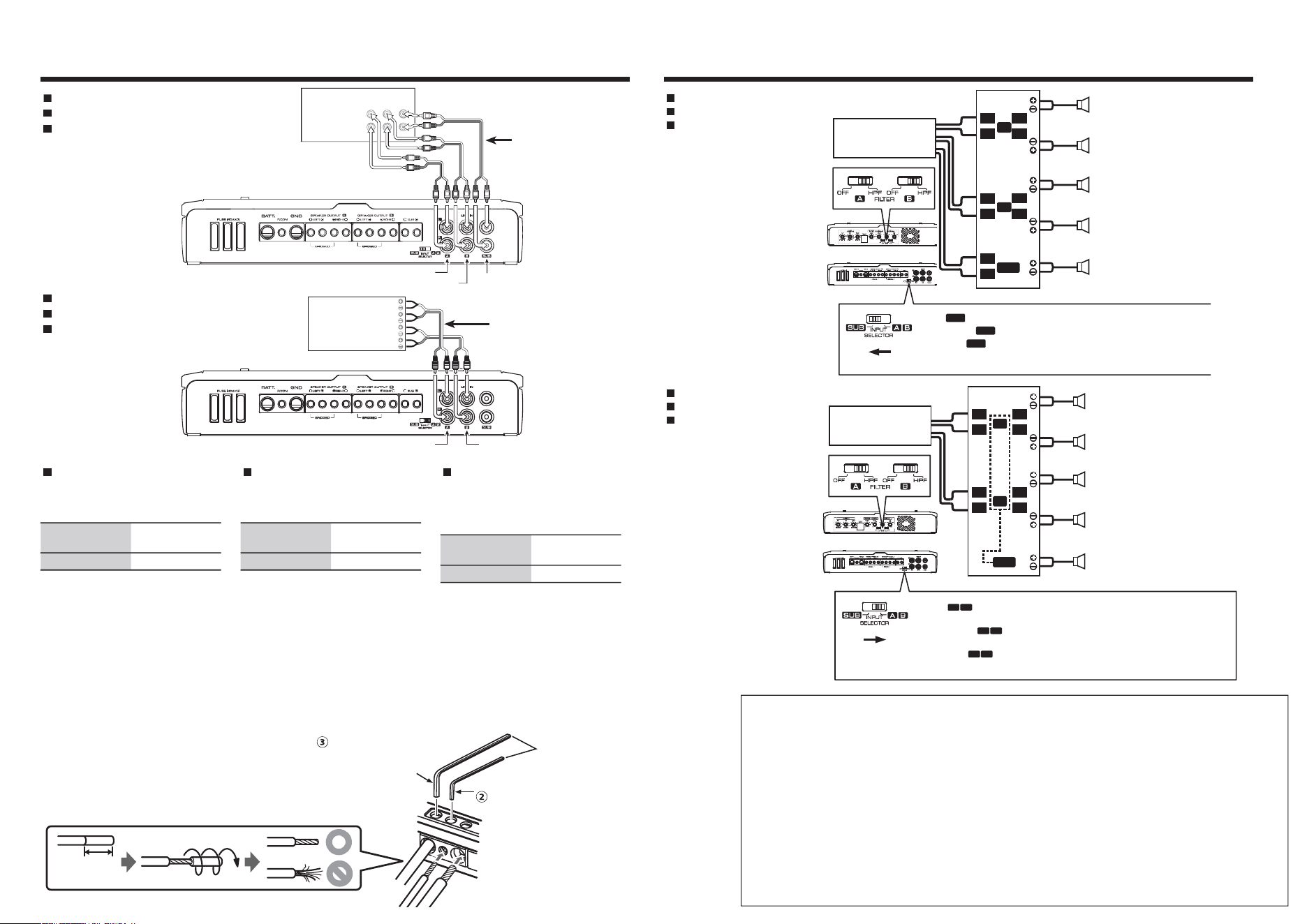
System examples / Exemple de configuration / Ejemplos del sistema
5-channel system (1)
Système 5 voies (1)
Sistema de 5 canales (1)
5-channel system (2)
Système 5 voies (2)
Sistema de 5 canales (2)
L
R
L
R
L
R
L
R
A
B
SUB
HEAD UNIT
L
R
L
R
L
R
L
R
A
B
L
R
SUB
HEAD UNIT
Front left speaker
Haut-parleur avant gauche
Altavoz delantero izquierdo
Front left speaker
Haut-parleur avant gauche
Altavoz delantero izquierdo
Front right speaker
Haut-parleur avant droit
Altavoz delantero derecho
Front right speaker
Haut-parleur avant droit
Altavoz delantero derecho
Rear left speaker
Haut-parleur arrière gauche
Altavoz trasero izquierdo
Rear left speaker
Haut-parleur arrière gauche
Altavoz trasero izquierdo
Rear right speaker
Haut-parleur arrière droit
Altavoz trasero derecho
Rear right speaker
Haut-parleur arrière droit
Altavoz trasero derecho
Subwoofer (L+R)
Haut-parleur d’extrêmes graves (G+D)
Altavoz de subgraves (I+D)
Subwoofer (L+R)
Haut-parleur d’extrêmes graves (G+D)
Altavoz de subgraves (I+D)
Select
SUB
when there is connection to the SUB input.
Sélectionnez
SUB
lorsqu’il n’y a aucune connexion à l’entrée SUB.
Seleccione
SUB
cuando haya conexión a la entrada SUB.
Select
BA
when there is no connection to the SUB input.
SUB output signal is created by this unit.
Sélectionnez
BA
lorsqu’il n’y a aucune connexion à l’entrée SUB. Le
signal de sortie SUB est créé par cet appareil.
Seleccione
BA
cuando no haya conexión a la entrada SUB.
La señal de salida SUB se crea mediante esta unidad.
FACTORY INSTALLED
HEAD UNIT
SPEAKER OUTPUT
R-FRONT-LR- REAR -L
A.ch B.ch
AFTER MARKET
HEAD UNIT
REAR
L
R
FRONT
SUB
L
R
R
L
L
R
R
L
L
R
R
L
A.ch
B.ch
SUB
RCA INPUT connection
Raccordement RCA INPUT
Conexión RCA INPUT
SPEAKER INPUT connection
Raccordement SPEAKER INPUT
Conexión SPEAKER INPUT
RCA cable
Câble RCA
Cable RCA
Speaker line to male RCA
adapter
Ligne de haut-parleur à
adaptateur RCA mâle
Línea de altavoz a
adaptador RCA macho
About the Lead Terminals
1. Wire Thicknesses
You can use wires with the following
thicknesses:
Battery wire and
ground wire
AWG 4 – AWG 6
Speaker wire AWG 8 – AWG 16
2. Strip the wire
Make a cut in the wire sheath
(insulator made from vinyl, etc.) at the
position 10–13 mm (3/8”–1/2”) away
from the end of the wire, and then
remove the unnecessary portion of
the sheath by twisting it.
3. Install the wire
Loosen the screw using the supplied
hexagon wrench. Insert the conductor
of the wire in the terminal hole, and
then tighten the screw.
À propos des bornes de câble
1. Épaisseurs des câbles
Vous pouvez utiliser des câbles aux
épaisseurs suivantes.
Câble de batterie
et câble de masse
AWG 4 – AWG 6
Câble d'enceinte AWG 8 – AWG 16
2. Dénuder le câble
Coupez la gaine du câble (isolant
en vinyle, etc.) à environ 10–13 mm
(3/8”–1/2”) de l'extrémité du câble,
puis enlevez la portion de gaine inutile
en la faisant tourner dans vos doigts.
3. Installer le câble
Desserrez la vis à l'aide de la clé
hexagonale fournie. Insérez le fil
conducteur du câble dans l'orifice de
la borne, puis serrez la vis.
Acerca de los terminales con-
ductores
1. Grosores de cables.
Puede utilizar cables con los siguientes
grosores:
Cable de batería
y cable de tierra
AWG 4 – AWG 6
Cable de altavoz AWG 8 – AWG 16
2. Pele el cable.
Realice un corte en el revestimiento del
cable (aislante de vinilo, etc.) a 10–13
mm (3/8”–1/2”) del extremo del cable y,
a continuación, retire la parte innecesa-
ria del revestimiento torciéndola.
3. Instale el cable.
Afloje el tornillo con la llave hexagonal
suministrada. Inserte el conductor del
cable en el orificio del terminal y apriete
el tornillo.
Hexagon wrench
Clé polygonale
Llave hexagonal
Parts included
Pièces comprises
Partes incluidas
(2.5 mm)
Parts included
Pièces comprises
Partes incluidas
(4.0 mm)
10–13 mm
(3/8
”–
1/2
”
)
For U.S.A.
FCC WARNING
This equipment may generate or use radio frequency energy. Changes or modifications to this equipment may cause harmful
interference unless the modifications are expressly approved in the instruction manual. The user could lose the authority to
operate this equipment if an unauthorized change or modification is made.
FCC NOTE
This equipment has been tested and found to comply with the limits for a Class B digital device, pursuant to Part 15 of the
FCC Rules. These limits are designed to provide reasonable protection against harmful interference in a residential installation.
This equipment may cause harmful interference to radio communications, if it is not installed and used in accordance with the
instructions. However, there is no guarantee that interference will not occur in a particular installation. If this equipment does
cause harmful interference to radio or television reception, which can be determined by turning the equipment off and on,
the user is encouraged to try to correct the interference by one or more of the following measures:
• Reorient or relocate the receiving antenna.
• Increase the separation between the equipment and receiver.
• Connect the equipment into an outlet on a circuit different from that to which the receiver is connected.
• Consult the dealer or an experienced radio/TV technician for help.
Loading ...
Loading ...
Loading ...