
Part No. 7242433 (Rev. D 3/14/12)
REPLACEMENT VALVE ASSEMBLY
INSTALLATION INSTRUCTIONS
Note: Before attempting to replace the valve, close the shut off valve on the house main water line,
near the water meter or pressure tank. Open a nearby conditioned water faucet to vent pressure
from the unit. Unplug the transformer from electrical power.
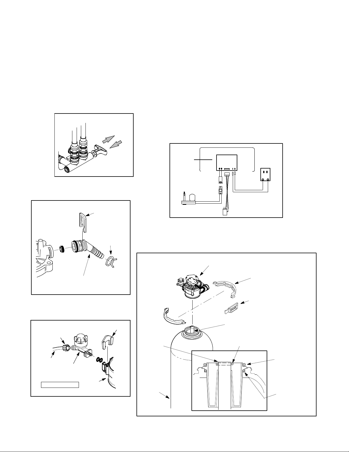
1. Push the bypass valve stem in for bypass. Figure 1.
2. Remove the salt hole cover and set aside.
3. Slide the top cover forward to expose valve.
4. Carefully disconnect wiring harness from position switch. Figure 2.
5. Carefully unplug the motor terminals from the back of the electronic control board. Fig-
ure 2.
6. Set top cover aside.
7. Carefully remove the large retainer clips on the softener inlet and outlet. Separate the
water softener from the bypass valve.
8. Using a needle nose pliers, lift up on drain clip and remove valve drain hose adapter
from valve. Set aside. Figure 3.
9. Remove brine line by loosening the nut ferrule on the end of the nozzle and venturi as-
sembly. Figure 4.
10. Remove retainer clips and clamps from around the tank neck. Set aside. Figure 5.
11. Remove valve from resin tank and set aside. Figure 5.
12. With all o--rings (lubricated with silicone grease) and the top d istributor in place in the
top of the tank, check the riser pipe length. It should be about even with the top edge
of the top distributor. Figure 4.
13. Be sure all parts are clean and free of resin beads and other debris, including the bot-
tom of the valve assembly. Lightly lubricate the o--ring sealing surface in the inside of
the valve port, at the bottom of the valve. Figure 5.
14. Locate the distributor o--ring at the very top of the riser pipe as shown in Figure 5.DO
NOT SLIDE IT DOWN TO REST AGAINST THE TOP DISTRIBUTOR.
15. Carefully lower the new valve assembly onto the tank, aligning it with the riser pipe, and
work over the o--ring and onto the adaptor. T hen clamp in place. Figure 5.
16. Carefully reconnect the water softener valve inlet and outlet back together with the by-
pass valve. Attach with large retainer clips.
17. Reattach brine line by hand--tightening the nut ferrule onto the end of the nozzle and
venturi assembly.
18. Remove hose clamp from valve drain hose adaptor and attach drain tubing to new
valve drain hose adaptor. Secure with old hose clamp. Figure 3.
19. Carefully reconnect the motor terminals to the back of the electronic control board.
Reattach the position switch wire harness onto the position switch. Figure 2.
20. Fully open the house main water supply valve. Observe a steady flow of water with no
air bubbles from the open faucet.
Part No. 7242433 (Rev. D 3/14/12)
21. SLOWLY MOVE THE BYPASS VALVE STEM TOWARD THE SOFT WATER POSI-
TION, PAUSING SEVERAL TIMES TO ALLOW UNIT TO PRESSURIZE. Figure 1.
22. After about three minutes, open a hot water faucet for about one minute, or until all air
is expelled, then close.
23. Close all cold water faucets and check your plumbing connections for leaks.
24. To verify proper function of the softener, complete the manual advance diagnostics as
outlined in the In stallatio n/Operation manual.
Transformer
position
switch
valve motor
BACK OF
TIMER
Figure 2
"
Figure 1
Nut Ferrule
Brine Line
Nozzle and
Venturi
Retainer Clip
Valve
Silicone Grease
Figure 4
riser pipe, or standpipe
resin
tank
valve
assembly
clamp retainer (2)
clamp section (2)
o---ring, 13/16” x 1---1/16”
(locate at top of riser, as shown)
o --- r i n g ,
2---7/8” x 3---1/4”
(thick)
o --- r i n g ,
2---3/4’ x 3”
(thin)
Figure 5
flushwithtop
distributor
drain clip
hose clip
valve drain
hose adaptor
Figure 3
bypass valve
PUSH IN
for bypass
PULL OUT
for soft water