Loading ...
Loading ...
Loading ...
This product must be correctly assembled before use.
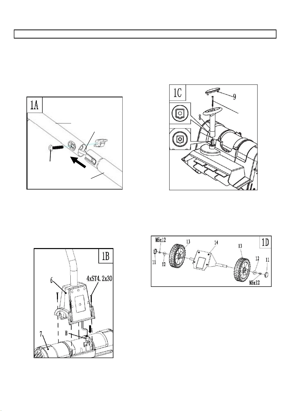
Handle (Fig. 1A)
Slide the lower section (C) into the upper section (B).
Line up the holes on each tube, and make sure the
cable (A) is clear of the mounting holes. Secure the two
sections together with the M6x45 carriage bolt and wing
nut.
Motor housing (Fig. 1B)
Remove the plug guard and connect socket (B) on the
upper cover (6) to the plug on the motor housing (7).
Secure the upper cover to the motor housing with the
ST4.2 x 30 Philips head self tapping screws.
ASSEMBLY
Adjust knob (Fig. 1C)
Align the rib on the spindle with the notch on the
adjusting knob and push the adjusting knob onto the
spindle. Secure the knob with the ST4.0x50 Philips head
self tapping screw. Place the adjust knob cover onto the
top and push to secure into place.
Wheel (Fig. 1D)
Remove the screws and washers from the wheel bracket.
Install the wheels (13) and secure into place with the
washers and M5 x 12 screws. Push wheel covers into
place.
M6x45 Carriage
Bolt
B
C
A
ST4.0x50
7
Model SN74016
Loading ...
Loading ...
Loading ...