Loading ...
Loading ...
Loading ...
10;Re_n_e the: headstock pu_l!ey using the 5/32" set-
- = scre_Wrench_ _ _:
1-i. Find four pan head thread cutting screws 3/8" long
and four Iockwashers from among the loose parts,
: Attach the belt guard with these screws and Iockwash-
ere, The arrows in this illustration show the location of
the screws.
12. P|ace the headstock pulley onto the headstock shaft as
shown, Position it so that the end of the pulley is ftush
with theend of the lathe spindle.
13, Place the motor pulley on the motor shaft so that the
small diameter is approximately 1/16" away from the
motor.
14. NOTE: When installing the pulley on a 5/8" diameter
motor shaft, make sure that the 3/16" square key
furnished with your motor is in place. Then tighten the
setscrew with a 5/32" setscrew wrench.
i i -¸ i ¸
/
/
/
/
/
/
3/16 x 3/16 KEY
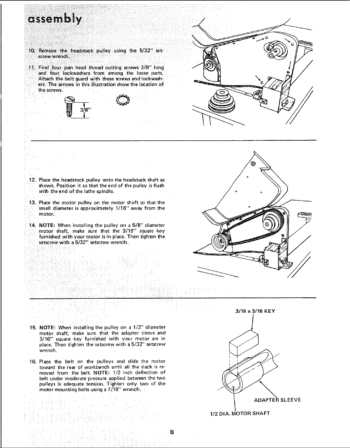
15. NOTE: When installing the pulley on a 112" diameter
motor shaft, make sure that the adapter sleeve and
3/16" square key furnished with your motor are in
place. Then tighten the setscrew with a 5/32" setscrew
wrench.
16, Place the belt on the pulieys and slide the motor
toward the rear of workbench until ait the slack is re-
moved from the belt. NOTE: 1/2 inch deflection of
belt under moderate pressure applied between the two
pulleys is adequate tension, Tighten only two of the
motor mounting bolts using a 7/t6, wrench.
J
ADAPTER SLEEVE
1/2 DIA. MOTOR SHAFT
Loading ...
Loading ...
Loading ...