
1
IntellIgent WIre-Free
Smoke Alarm User guide
Photoelectric Smoke Alarm
with Voice and Hardwire/Wireless Interconnect
Model P4010ACS-W
Model P4010LACS-W (Safety Light)
WIre-Free Interconnect:
You do NOT need a home wi-fi system to use
these units. Multiple wireless units create their
own independent wireless alarm network.
120V HArdWIre
10-yeAr bAttery bAckUp
HArdWIre & WIre-Free
Interconnect
VoIce AlArM
SMoke AlArM
P/N: 1314-7201-02 Rev A

2
Thank You for Purchasing this Kidde Smoke Alarm
Hardwired for 120VAC, these models feature a non-replaceable, sealed-in battery backup. They also contain a
voice message system and SMART Hush® Control to temporarily silence nuisance alarms. They are capable of
both Hardwire and Wireless Interconnect.
reAd SectIon 9: Activation and Wireless Alarm Network, before powering the units. You do NOT need a
home wi-fi system to use these units. Multiple wireless units create their own independent wireless alarm
network.
Teach children how to respond to the alarm and that they should never play with the unit. Your Kidde Smoke Alarm was
designed for use in a residential environment. It is not designed for use in a recreational vehicle (RV) or boat.
note: Please thoroughly read this user guide and save the document for future reference and to pass on to any
subsequent owner.
The National Fire Protection Association (NFPA) and
the manufacturer recommend replacing this alarm
ten years from the date code on back of alarm.
Model (on back): ___________________
Date Code (on back): ___________________
Date of Purchase: ___________________
Where Purchased: ___________________
Date to Replace: ___________________
Product Support: 800-880-6788
Please write down the below information
and have this at hand when you call.
3
Contents
1. Smoke Alarm: What To Do When The Alarm Sounds . . . . . . . . . . . . 4
2. Carbon Monoxide Alarm: What To Do When The Alarm Sounds . . . . . . . . 5
3. Other Alarm Visual And Audible Indicators . . . . . . . . . . . . . . . . 6
4. Troubleshooting Guide . . . . . . . . . . . . . . . . . . . . . . . 7
5. Introduction, Product Features & Specifications . . . . . . . . . . . . . . 10
6. Limitations Of Smoke Alarms . . . . . . . . . . . . . . . . . . . . . 11
7. Recommended Locations For Smoke Alarms . . . . . . . . . . . . . . . 12
8. Locations To Avoid . . . . . . . . . . . . . . . . . . . . . . . . . 14
9. Activation And Wireless Alarm Network . . . . . . . . . . . . . . . . . 15
9.1 Setting Up A Wireless Alarm Network. . . . . . . . . . . . . . . . . 15
9.2 Adding Another Device to an Existing Wireless Alarm Network . . . . . . . 17
9.3 Resetting a Device’s Wireless Settings . . . . . . . . . . . . . . . . 18
10. Wiring Instructions . . . . . . . . . . . . . . . . . . . . . . . . 19
11. Operation And Testing . . . . . . . . . . . . . . . . . . . . . . . 24
12. Recognizing Nuisance Alarms . . . . . . . . . . . . . . . . . . . . 26
13. Battery Back Up. . . . . . . . . . . . . . . . . . . . . . . . . . 28
14. Permanently Disable Alarm / Discharge Battery. . . . . . . . . . . . . . 29
15. Cleaning Your Alarm . . . . . . . . . . . . . . . . . . . . . . . . 30
16. Good Safety Habits . . . . . . . . . . . . . . . . . . . . . . . . 31
17. Service And Warranty . . . . . . . . . . . . . . . . . . . . . . . 34

4
1. Smoke Alarm: What To Do When the Alarm Sounds
Smoke alarm pattern is three long beeps with voice “Fire!,” a 1.5 second pause, and three long beeps repeating. The red LED
blinks in time with alarm pattern.
• Alert small children in the home as well as anyone else that might have difficulty recognizing the importance of the
alarm sounding or that might have difficulty leaving the area without help.
• Leave immediately by your escape plan. Every second counts, so don’t waste time getting dressed or picking up
valuables.
• In leaving, don’t open any inside door without first feeling its surface. If hot, or if you see smoke seeping through
cracks, don’t open that door! Instead, use your alternate exit. If the inside of the door is cool, place your shoulder
against it, open it slightly and be ready to slam it shut if heat and smoke rush in.
• If the escape route requires you to go through smoke, stay close to the floor where the air is cleaner. Crawl if neces-
sary, and breathe shallowly through a cloth, wet if possible.
• Once outside, go to your selected meeting place and make sure everyone is there.
• Call the fire department from your cell phone outside, or from your neighbor’s home-not from yours!
• Don’t return to your home until the fire officials say that it is all right to do so.
• There are situations where a smoke alarm may not be effective to protect against fire as stated in the NFPA Standard
72. For instance:
a) smoking in bed
b) leaving children home alone
c) cleaning with flammable liquids, such as gasoline
note: See Section RECOGNIZING NUISANCE ALARMS, for nuisance alarm situations.

5
2. Carbon Monoxide Alarm: What To Do When the Alarm Sounds
note: This is not a carbon monoxide (CO) alarm, but will receive and transmit a CO alarm signal (with voice mes-
sage) from an interconnected CO or combination smoke / CO alarm.
Carbon monoxide (CO) alarm pattern is four quick beeps with voice “Warning! Carbon Monoxide” repeating every 5
seconds. The red LED blinks in time with alarm pattern.
WArnIng: cArbon MonoxIde AlArM ActIVAtIon IndIcAteS tHe preSence oF cArbon Mon-
oxIde (co) At HIgH concentrAtIonS WHIcH cAn kIll yoU.
1) Operate the Test/Hush button. note: Pressing the button on the initiating alarm unit (green LED flashing every sec-
ond) will silence the alarm notification, including all interconnected units. If the unit goes into alarm mode again within
six minutes, it is sensing high levels of CO which can quickly become a dangerous situation.
2) Call your emergency services (Fire Department or 911). eMergency pHone #: _______________________
3) Immediately move to fresh air — outdoors or by an open door / window. Do a head count to check that all persons are
accounted for. Alert small children in the home as well as anyone else that might have difficulty recognizing the impor-
tance of the alarm sounding or that might have difficulty leaving the area without help. Do not reenter the premises nor
move away from the open door/window until the emergency services responders have arrived, the premises have been
aired out, and your alarm remains in its normal condition.
4) After following steps 1-3, if the alarm reactivates within a 24 hour period, repeat steps 1-3 and call a qualified appli-
ance technician to investigate sources of CO from fuel burning equipment and appliances, and to inspect for proper
operation of equipment.
If problems are identified during this inspection, have the equipment serviced immediately. Note any combustion equipment
not inspected by the technician and consult the manufacturer’s instructions, or contact the manufacturer directly for more
information about CO safety and the equipment. Make sure that motor vehicles are not, or have not been, operating in a garage
attached or adjacent to the residence. Never restart the source of a CO problem until it has been corrected. Never ignore the
sound of the alarm! note: See Section RECOGNIZING NUISANCE ALARMS, for nuisance alarm situations.

6
3. Other Alarm Visual and Audible Indicators
Operational Mode Visual Indications Audible Indications Action/Note:
normal (standby) AC power: Green LED on continu-
ously during light conditions, or blink
every 60 sec during dark conditions.
DC power: Green LED blink approx
every 60 sec.
test (button press when
no alarm condition is
present)
• 4 patterns of Red/Amber/Green.
• Test: Red LED blinks in time with
alarm pattern. Safety light will briey
illuminate on model P4010LACS-W.
• Green LED fade on/o at
test complete.
• Button press sound
• Voice: "Testing, this is very loud.
Press now to cancel test. 5, 4, 3, 2, 1."
• 3 long beeps, Voice "Fire!", 3 long
beeps, Voice "Test Complete," Power
on/reset sound.
• Voice "Test Canceled" if button
pushed before test sequence begins.
Perform Test/Hush button
press once a week to verify
proper alarm operation
* Push/release button before
the countdown ends to
cancel test.
Smoke Alarm Memory
(unit has experienced
a smoke alarm event
within the last hour)
Red and Amber LED alternate on 1
sec, every 10 sec.
After button push: "Smoke previously
detected," only on the initiating
alarm unit.
Push test button to clear
Alarm Memory. NOTE: stan-
dard test sequence will follow.
(Push/release button again to
cancel test).
Smoke Alarm Hush
Mode, (SMArt HUSH®
control)
Red LED blinks every 2 sec. After button push: "Hush Mode
Activated."
Smoke alarm pattern stops.
(If there is too much smoke to allow
Hush: Voice "Too Much Smoke, Alarm
cannot be Hushed" Smoke alarm
pattern continues.)
This feature is to be used
only when a known alarm
condition, such as smoke from
cooking, activates the alarm.
locate None After button push on non-initiating
unit, only initiating unit continues
alarm pattern.
Use this to quickly locate the
alarm source and determine if
alarm is nuisance or real.
Smoke Alarm Hush
Mode canceled
None Voice message "Hush Mode
Canceled."
When smoke levels drop
below the alarm threshold,
the voice message "Hush
Mode Canceled" will occur .
Initiating Alarm,
(Multiple alarms in an
interconnected system)
Green LED blinks once per sec indi-
cating that this is the unit initiating
the alarm in an interconnected,
multiple alarm, system.
Unit in Smoke Alarm mode. During alarm, the initiating
alarm red blink will be inter-
rupted by a green blink.
7
4. Troubleshooting Guide
Trouble Condition Visual Indications Audible Indications Action:
low battery
Amber
LED
blinks
every
5
seconds
Chirp every 60 sec, voice every
30 sec: “Replace alarm.”
Voice stops after 5 mins.
*Remove, discharge, dispose unit, and replace as
soon as possible.
Fault Mode Chirp every 30 sec.
Voice every 30 sec: “Error, see
trouble shooting guide”
After 5 mins: no voice message
*See Cleaning Your Alarm section.
* Push Test/Hush button once to attempt to reset
the unit .
*Red LED will blink out an error code (number of
blinks) when Test/Hush button is push/released
once. Report the number of blinks to customer
service if needed.
end of Unit life Double chirp every 30 sec.
First 5 mins: Voice every 30 sec:
“Replace alarm, press button to
temporarily silence.” Voice stops
after 5 mins. After 7 days: Chirps
continue. Voice every 30 sec for
5 mins: “Replace alarm.”
* Push/release Test/Hush button to temporarily
silence (see End of Unit Life Hush Mode section
below)
* Remove, discharge, dispose unit, and replace as
soon as possible.
end of Unit life Hush
Mode (after push/
release test/Hush
button during end
of life)
Voice “Temporarily Silenced.”
End of Unit Life chirps silenced
for 24 hrs. (7 days after End of
Unit Life chirps begin, the chirps
cannot be silenced.)
* Remove, discharge, dispose unit, and replace as
soon as possible.
network error Chime every 30 secs. Voice
every 30 sec: “Connection lost,
press button to temporarily
silence.”
After 5 min: no voice messages
(Note: network must have
3 or more alarms for voice
messages.)
See next page for Network Error troubleshooting
tips.
network error Hush
(after button push
during network error)
Voice “Temporarily
Silenced.”
If you require further information please contact Product Support at 1-800-880-6788 or write us at:
Kidde, 1016 Corporate Park Drive, Mebane, NC 27302. Our internet address is www.kidde.com.

8
Network Error Troubleshooting Tips
If you have a unit (or units) in network error and you would like to silence them, you can push and release the Test/Hush
button once on each unit in network error to silence them for 24 hours at a time. NOTE: when you do this, the red LED
will blink out an error code (number of blinks) when the Test/Hush button is push/released once. If the following steps
are unsuccessful, it might be helpful to report the number of blinks to customer service.
Fix 1:
note: If there is only one unit that is giving you trouble, rotating the alarm on the mounting plate may re-orient the
wireless antenna and fix the problem.
1. Press and hold the button on a known working unit (not the unit in network error) for 4-5 seconds until you hear 2 beeps.
2. Go to the room/location of the unit in network error.
3. Rotate the network error unit 90 degrees in either direction on the mounting plate.
4. Press and hold the button on the network error unit for 4-5 seconds until you hear 2 beeps.
5. Within 10 seconds, the network error unit should re-join the wireless network and should show fading green lights,
with a voice “Success, now connected.” If this is the case, press and hold the button on the same unit for 4-5
seconds until 2 beeps are heard.
note: If the unit does not re-join the wireless network, press and hold the button on a known working unit (not the
unit in network error) for 4-5 seconds. Then proceed to “Fix 2.”
Fix 2:
note: In a wireless alarm network, there is a Coordinator unit, which controls communication to the other units, which
are called “RFDs”. For best wireless range, the Coordinator should be located in a central location of the household.
If “Fix 1” does not work or if there are multiple units in network error, the following steps will place the Coordinator of the
wireless network at the center of the household.
1. Go to a wireless unit that seems closest to the center of the house.
2. If this unit is not in network error, press and hold the button on that unit for 4-5 seconds until you hear 2 beeps, and a
voice “Searching for other devices,” as well as a sonar ping sound. If it is in network error go to “Fix 3” below.
3. You will now need to locate the Coordinator of the system.
a. The Coordinator will be fading green on/off every 2 seconds. The RFDs of the system will be fading green on/off
every 4 seconds.
b. The wireless network will stay open for 15 minutes. If the wireless network closes, press and hold the button on
any known working wireless unit for 4-5 seconds until 2 beeps are heard, followed by voice “Searching for other
devices,” as well as a sonar ping sound, to re-open the wireless network.

9
4. Once you have located the Coordinator of the wireless network, take the Coordinator down and swap it with the unit that
was deemed to be in the center of the house (found in steps 1 and 2).
5. Go to each unit that is in network error and press/hold the button on that unit for 4-5 seconds until you hear 2 beeps.
a. The unit should join back to the wireless network,with voice “Success, now connected.” The lights on the unit
should flicker once and then be fading green on/off every 4 seconds. If this is the case, press/hold the button on
any unit to close the wireless network
.
b. If the unit doesn’t join the network, rotate the unit 90 degrees in either direction.
c. If the unit still hasn’t joined the network, press and hold the button on a known working unit for 4-5 seconds to
close the wireless network and then proceed to “Fix 3.”
Fix 3:
If “Fix 2” did not work, use this fix. The following steps will reset the entire wireless alarm network and place the Coordinator at
the center of the household.
1. Take all wireless units down from their installed locations and set all units on a table.
2. Reset all the units one by one by pressing and holding the button for 8-9 seconds until you hear 3 beeps and a voice
“Resetting wireless settings.”
note: if resetting the units doesn’t result in the voice message “Ready to connect, follow quick start instructions”, the
unit needs to be replaced with a new one.
3. Create a new wireless alarm network by pressing and holding the button on any unit for 4-5 seconds until you hear 2
beeps, and voice, “Searching for other devices” with a sonar ping. Keep track of this unit, as it will become the Coordinator
of your wireless alarm network.
4. Wait for the other units to join the new wireless network. Each unit will announce “Success, now connected.”
5. After each unit has joined, press/hold the button for 4-5 seconds on the Coordinator unit.
6. Take the same unit (Coordinator) and install it closest to the center of the household.
a. Example 1: For a 2 floor house, install the unit on the main floor near the center of the main floor.
b. Example 2: For a 3 floor house, install the unit on the middle floor near the center of the middle floor.
7. Install the rest of the units around the house (you may place units in any location as instructed by this user guide).
If the network error persists after these attempted fixes, remove the unit, discharge it, and replace it with a new unit as
soon as possible. Contact customer service.

10
5. Introduction, Product Features and Specifications
Introduction
This alarm detects products of combustion using photoelectric technology. Ten (10) years after the unit was installed,
this unit will automatically alert you that it is time to replace the unit. This is called “End of Unit Life” mode. See Trouble-
shooting Guide.
To help identify the date to replace the unit, a label has been affixed to the side of the alarm. Write the “Install date” in
the space provided, and then write in the “Replace by” date (10 years from initial power up) in permanent marker on the
label prior to installing the unit. note: AC power must be connected to obtain the full 10 year battery and unit life.
product Features and Specifications:
• Temperature: Operating Range: 40°F (4.4°C) to 100°F (37.8°C)
• Humidity: Operating range: up to 95% RH non-condensing
• Audible Alarm: 85+ dB at 10’ 3.0 to 3.5 KHz pulsing alarm, with voice messages “Fire!”
note: This is not a CO alarm, but it will receive and transmit a CO alarm signal (with voice message
“Warning! Carbon Monoxide”) from an interconnected CO or combination smoke/CO alarm.
• Smoke Sensor: Photoelectric
• Voice message system
• Smoke Alarm SMART Hush® Control
• Ambient Light Sensing
• Powered by 120VAC (60 Hz, 53 mA max) wire-in connector with sealed lithium battery backup.
• Hardwire and wireless interconnectable to other compatible alarms.
• One large, user- friendly button.
• LED safety light on model P4010LACS-W to help illuminate escape pathways.

11
6. Limitations of Smoke Alarms
WArnIng: pleASe reAd cAreFUlly And tHoroUgHly
• Life safety from fire in residential occupancies is based primarily on early notification to occupants of the need to
escape, followed by the appropriate egress actions by those occupants.
• Fire warning systems for dwelling units are capable of protecting about half of the occupants in potentially fatal
fires. Victims are often intimate with the fire, too old or young, or physically or mentally impaired such that they
cannot escape even when warned early enough that escape should be possible. For these people, other strategies
such as protection-in-place or assisted escape or rescue are necessary.
• Leading authorities recommend that both ionization and photoelectric smoke alarms be installed to help insure
maximum detection of the various types of fires that can occur within the home. Ionization sensing alarms may
detect invisible fire particles (associated with fast flaming fires) sooner than photoelectric alarms. Photoelectric
sensing alarms may detect visible fire particles (associated with slow smoldering fires) sooner than ionization alarms.
• A battery powered alarm must have a battery of the specified type, in good condition and installed properly (This
model has a sealed backup battery).
• Smoke alarms must be tested regularly to make sure the battery and the alarm circuits are in good operating condition.
• Smoke alarms cannot provide an alarm if smoke does not reach the alarm. Therefore, smoke alarms may not sense
fires starting in chimneys, walls, on roofs, on the other side of a closed door or on a different floor.
• If the alarm is located outside the bedroom or on a different floor, it may not wake up a sound sleeper.
• The use of alcohol or drugs may also impair one’s ability to hear the smoke alarm. For maximum protection, a smoke
alarm should be installed in each sleeping area on every level of a home.
This alarm is not intended to alert hearing impaired individuals.

12
7. Recommended Locations for Smoke Alarms
• Locate smoke alarms in all sleeping areas. Try to monitor the exit path as the bedrooms are usually farthest from the
exit. If more than one sleeping area exists, locate additional alarms in each sleeping area.
• Locate additional alarms to monitor any stairway as stairways act like chimneys for smoke and heat.
• Locate at least one alarm on every floor level.
• Locate an alarm in every bedroom.
• Locate an alarm in every room where electrical appliances are operated (i.e. portable heaters or humidifiers).
• Locate an alarm in every room where someone sleeps with the door closed. The closed door may prevent an alarm
not located in that room from waking the sleeper.
• Smoke, heat, and combustion products rise to the ceiling and spread horizontally. Mounting the smoke alarm on
the ceiling in the center of the room places it closest to all points in the room. Ceiling mounting is preferred in
ordinary residential construction.
ANYWHERE ALONG
THIS BOLD SURFACE
Locations permitted for smoke
alarms and smoke detectors
on tray-shaped ceilings.
ANYWHERE ALONG
THIS BOLD SURFACE
Locations permitted for smoke
alarms and smoke detectors
on tray-shaped ceilings.
ANYWHERE ALONG
THIS BOLD SURFACE
Locations permitted for smoke
alarms and smoke detectors
on tray-shaped ceilings.
ANYWHERE ALONG
THIS BOLD SURFACE
Locations permitted for smoke
alarms and smoke detectors
on tray-shaped ceilings.
ANYWHERE ALONG
THIS BOLD SURFACE
Locations permitted for smoke
alarms and smoke detectors
on tray-shaped ceilings.
ANYWHERE ALONG
THIS BOLD SURFACE
Locations permitted for smoke
alarms and smoke detectors
on tray-shaped ceilings.
NFPA 72 states: “Smoke alarms in rooms with ceiling
slopes greater than 1 ft in 8 ft (.3m in 2.4 m) horizontally
shall be located on the high side of the room.” NFPA 72
states: “A row of detectors shall be spaced and located
within 3 ft (0.9m) of the peak of the ceiling measured
horizontally.”
Figure 7-A
Figure 7-B Figure 7-C

13
• For mobile home installation, select locations carefully to avoid thermal barriers that may form at the ceiling. For
more details, see MOBILE HOME INSTALLATION section.
• When mounting an alarm on the ceiling, locate it at a minimum of 4” (10 cm) from the side wall.
• When mounting the alarm on the wall, use an inside wall with the top edge of the alarm at a minimum of 4” (10 cm)
and a maximum of 12” (30.5 cm) below the ceiling.
• Put smoke alarms at both ends of a bedroom hallway or large room if the hallway or room is more than 30 feet (9.1
m) long.
• Install Smoke Alarms on sloped, peaked or cathedral ceilings at or within 3ft (0.9m) of the highest point (measured
horizontally).
This equipment should be installed in accordance with the National Fire Protection Association’s 72 (National Fire Protec-
tion Association, Batterymarch Park, Quincy, MA 02269).
Mobile Home Installation
Modern mobile homes have been designed and built to be energy efficient. Install smoke alarms as recommended
above. In older mobile homes that are not well insulated compared to present standards, extreme heat or cold can be
transferred from the outside to the inside through poorly insulated walls and roof. This may create a thermal barrier
which can prevent the smoke from reaching an alarm mounted on the ceiling. In such units, install the smoke alarm on
an inside wall with the top edge of the alarm a minimum of 4” (10 cm) and a maximum of 12” (30.5 cm) below the ceiling.
If you are not sure about the insulation in your mobile home, or if you notice that the outer walls and ceiling are either
hot or cold compared to the room air temperature, install the alarm on an inside wall. NFPA 72 (National Fire Protection
Association) requires smoke alarms be installed in each sleeping area.
WArnIng: teSt yoUr AlArM operAtIon AFter MobIle HoMe HAS been In StorAge or Unoc-
cUpIed, And At leASt once A Week dUrIng USe.

14
8. Locations to Avoid
• In the garage. Products of combustion are present when you start your automobile.
• Normal cooking may cause nuisance alarms. If a kitchen alarm is desired, it should have an alarm silence feature or
be a photoelectric type.
• Do not install within 6 ft. of heating or cooking appliances.
• Less than 4” (10cm) from the peak of an “A” frame type ceiling.
• In an area where the temperature may fall below 40ºF or rise above 100ºF, such as garages and unfinished attics.
• In dusty areas. Dust particles may cause nuisance alarm or failure to alarm.
• In very humid areas (above 95% RH, non-condensing). Moisture or steam can cause nuisance alarms.
• In insect-infested areas.
• Smoke alarms should not be installed within 3 ft (.9m) of the door to a bathroom containing a tub or shower, forced
air supply ducts used for heating or cooling, ceiling or whole house ventilating fans, or other high air flow areas.
• Near lights. Electronic “noise” generated by the electronics may cause nuisance alarms.
• Do not install near vents, flues, chimneys.
• Do not install near fans, doors, windows or areas directly exposed to the weather.

15
9. Activation and Wireless Alarm Network
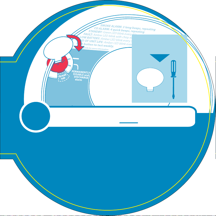
Upon initial power being applied (from rotating onto mounting plate or moving the red activation wheel to the “ON”
position - see Figure 9.1-B) these units are ready to connect to a network.
note: At any time during wireless alarm setup, if you have a problem, you can push and hold the Test/Hush
button on any problem unit until you hear three (3) beeps (approx 8 sec), and then release the button. The unit will
reset the unit’s wireless settings (described in Section 9.3). Once wireless settings are reset, the unit will prompt the
user to follow Quickstart instructions.
9.1 Setting Up a Wireless Alarm Network
Creating an interconnected wireless alarm network is a simple process, with intelligent “self-enrollment” features, and
user-friendly voice prompts.
A. reMoVe All deVIceS FroM tHeIr pAckAgIng
b. poWer Up All deVIceS
• Locate the red wheel on the back of the device. Turn the red wheel to
the “ON” position on ALL devices using the white tool included with the
Quick Start Guide, or a standard screwdriver.
• Once powered, the light rings will glow red and voice message will
announce,
“Ready to connect. Follow Quick Start instructions.”
note: If no further steps are taken within 15 minutes of initial power up, a voice prompt, “No devices found, not
connected” will be heard once, and the wireless function will turn off. The unit will then perform as a standard
hardwired alarm. See Section 9.3 for re-activating wireless.
Figure 9.1-B
ON
PERMANENTLY
DISABLE and
DISCHARGE
alarm
Break
tab
SMOKE ALARM: 3 long beeps, repeating
CO ALARM: 4 quick beeps, repeating
STANDBY: Green LED blink every 60s
FAULT: Amber LED blink with chirp every 30s
LOW BATTERY: Amber LED blink every 5s, chirp every 60s
END OF UNIT LIFE: Amber LED blink every 5s, chirp twice every 30s
Push button to test weekly.
See user guide for more information
USE ACTIVATION
TOOL OR SCREWDRIVER

16
c. pIck one deVIce
note: This chosen device will be the “Coordinator” of the wireless alarm network. Keep this unit separated from the
others. For best results, after wireless setup is complete, install the Coordinator in a central location.
Press and hold the button on only the Coordinator until you hear two beeps. Release button. You will hear “Searching for
other devices”.
• The light will pulse and device will sound a continuous “Sonar” ping until
step E is complete.
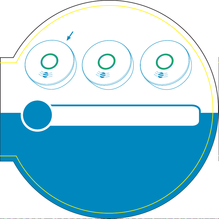
d. relAx And WAIt
note: For reference, these non-Coordinator units are called “RFDs”.
Wait until all other devices (RFDs) have connected to the network. Once
connected, each device will speak, “Success now connected!”
• Once connected, the lights will glow green.
e. pIck one deVIce
Press and hold the button on only ONE device until you hear 2 beeps.
Release button. “Sonar” ping will stop.
• Device will announce that setup is complete and the number of connect-
ed devices.
F. SetUp coMplete!
If all devices flash green and “Sonar” ping has stopped, the devices are
now connected. Congratulations!
IMportAnt: If for some reason, you forget which unit is the Coordinator,
follow these simple steps to re-confirm the Coordinator and the RFD units.
1. Press and hold the button on any unit for 4-5 seconds until 2 beeps are heard. Release button.
2. Observe the LED ring on each unit. The Coordinator will be fading green on/off every 2 seconds. The RFDs will
be fading green on/off every 4 seconds.
3. After confirming the Coordinator, press and hold the button on any unit for 4-5 seconds until 2 beeps are heard.
g. proceed to WIrIng InStrUctIonS In SectIon 10.
Figure 9.1-C
DON'T press buttons
on other devices
“Searching for
other devices.”
Hold for
5 seconds
Figure 9.1-D
“Success, now
connected!”
Figure 9.1-E
Hold for
5 seconds

17
9.2 Adding Another Wireless Device to an Existing Wireless
Alarm Network
For various reasons, you might want to add additional units to your existing wireless alarm network. Modifying your
existing wireless alarm network is easy and user-friendly.
A. reMoVe tHe neW deVIce FroM ItS pAckAgIng.
b. poWer Up neW deVIce
Locate the red wheel on the back of the device being added. Turn the red
wheel to the “ON” position using the white activation tool included in the
Quick Start Guide or a standard screwdriver.
• Once powered, the light ring will glow red.
c. pIck one InStAlled deVIce
Press and hold the button on ONE INSTALLED device on your network until
you hear two beeps. Release button. You will hear “Searching for other
devices.”
• Light will pulse green and device will sound a continuous “Sonar” ping
until step E is completed.
d. relAx And WAIt
Wait until the new device has connected to the network. Once connected,
the new device will speak, “Success now connected!”
• Once connected, the light ring will glow green.
Figure 9.2-B
ON
PERMANENTLY
DISABLE and
DISCHARGE
alarm
Break
tab
SMOKE ALARM: 3 long beeps, repeating
CO ALARM: 4 quick beeps, repeating
STANDBY: Green LED blink every 60s
FAULT: Amber LED blink with chirp every 30s
LOW BATTERY: Amber LED blink every 5s, chirp every 60s
END OF UNIT LIFE: Amber LED blink every 5s, chirp twice every 30s
Push button to test weekly.
See user guide for more information
USE ACTIVATION
TOOL OR SCREWDRIVER
Figure 9.2-C
Device Being Added
“Searching for
other devices.”
Installed Device
Figure 9.2-D
“Success, now
connected!”

18
e. pIck tHe InStAlled deVIce
Press and hold the button on the INSTALLED device for 5 SECONDS until you
hear two beeps. Release button. ”Sonar” ping will stop.
• Device will announce that setup is complete and the number of connect-
ed devices.
F. proceed to WIrIng InStrUctIonS In SectIon 10.
9.3 Resetting a Device’s Wireless Settings
If you encounter an issue at any point during the wireless network setup process, you may reset the device by following
the directions below.
A. begIn reSet
Press and hold the button on the device for 8-9 seconds until you hear 3
beeps. Release button. You will hear the words “Resetting wireless settings.”
b. conclUde reSet
Light ring will flash green once and then it will pulse red. You will hear the
words, “Ready to connect, follow quick start instructions.”
• Device has been reset.
• See Section 9.1 to begin set-up of a new wireless alarm network,
or Section 9.2 for adding this device to an existing alarm network.
note: If no further steps are taken within 15 minutes of resetting the unit’s wireless settings, a voice prompt “No
devices found, not connected” will be heard once, and the wireless function will turn off. The unit will then perform as
a standard hardwired alarm. See Section 9.2 for adding this device to an existing alarm network.
Figure 9.2-E
Added Device
“Setup
complete!”
Installed Device
Figure 9.3-A
Hold for
8-9 seconds
“Resetting
wireless
settings.”
Figure 9.3-B
“Ready to
connect, follow
Quick Start
instructions.”

19
10. Wiring Instructions
Wiring requirements
• This alarm should be installed on a UL Listed or recognized junction box. All connections should be made by a
qualified electrician and all wiring used shall be in accordance with articles 210 and 300.3(B) of the U.S. National
Electrical Code ANSI/NFPA 70, NFPA 72 and/or any other codes having jurisdiction in your area. The multiple station
interconnect wiring to the alarms must be run in the same raceway or cable as the AC power wiring. In addition, the
resistance of the interconnect wiring shall be a maximum of 10 ohms.
• The appropriate power source is 120 Volt AC Single Phase supplied from a non-switchable circuit, which is not
protected by a ground fault interrupter.
• Smoke alarms are not to be used with detector guards unless the combination (alarm and detector guard) have
been evaluated and found suitable for that purpose.
WArnIng: tHe AlArM cAnnot be operAted FroM poWer derIVed FroM A SqUAre WAVe,
ModIFIed SqUAre WAVe or ModIFIed SIne WAVe, InVerter. tHeSe typeS oF InVerterS Are
SoMetIMeS USed to SUpply poWer to tHe StrUctUre In oFF grId InStAllAtIonS, SUcH AS
SolAr or WInd derIVed poWer SoUrceS. tHeSe poWer SoUrceS prodUce HIgH peAk VoltAgeS
tHAt WIll dAMAge tHe AlArM.
Wiring Instructions for Ac quick connect Harness
cAUtIon: Turn off the main power to the circuit before wiring the alarm.
• For alarms that are used as single station, DO NOT CONNECT THE RED WIRE TO ANYTHING. Leave the red wire insu-
lating cap in place to make certain that the red wire cannot contact any metal parts or the electrical box.
20
• When alarms are hardwire interconnected, all interconnected units must be powered from a single circuit.
• A maximum of 24 Kidde Safety devices may be interconnected in a multiple station arrangement. The interconnect
system should not exceed the NFPA interconnect limit of 12 smoke alarms and/or 18 alarms total (smoke, CO, Smoke/
CO Combination, heat, etc.). With 18 alarms interconnected, it is still possible to interconnect up to a total of 6 remote
signaling devices and / or relay modules.
• The maximum wire run distance between the first and last unit in an interconnected system is 1000 feet.
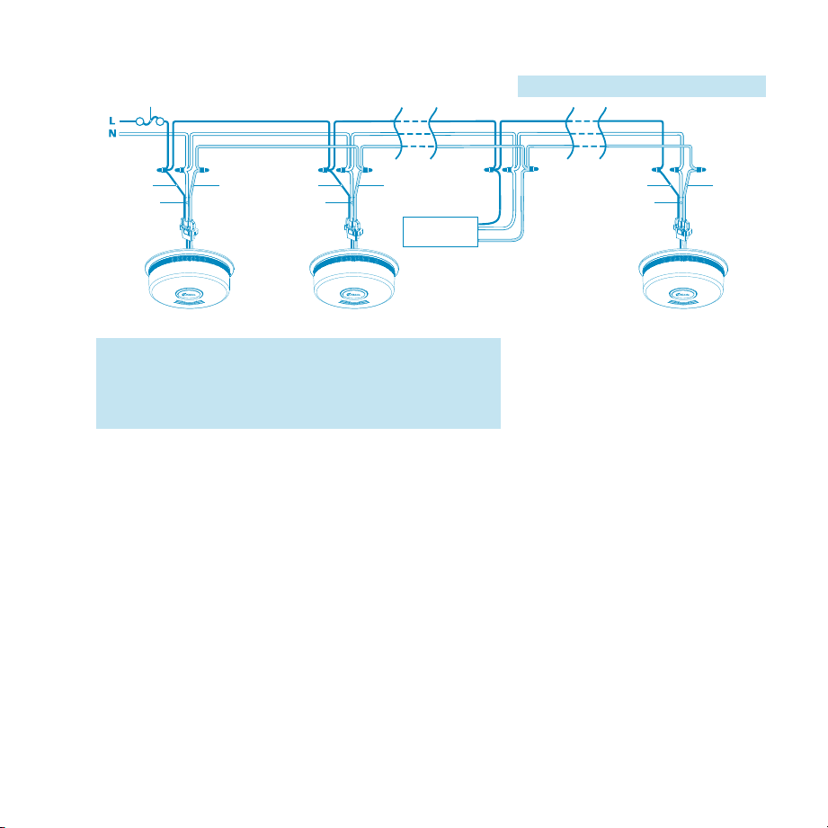
• Figure 10-A illustrates interconnection wiring. Improper connection will result in damage to the alarm, failure to
operate, or a shock hazard.
• Make certain alarms are wired to a continuous (non-switched) power line.
note: Use standard UL Listed household wire (as required by local codes) available at all electrical supply
stores and most hardware stores.
Additional
Alarm
REDBLACK
WHITE
Additional
Alarm
RED
BLACK
WHITE
FUSE OR CIRCUIT BREAKER
REDBLACK
WHITE
Kidde Relay Module
SM120X, CO120X
or both
Optional
Accessory
First
Alarm
Figure 10-A, Interconnect Wiring Diagram
Wires on alarm harness: Connected to:
Black: Hot side of AC line
White: Neutral side of AC line
Red: Interconnect lines (red wires) of other
units in the multiple station set-up

21
note: AC power should be turned off at this stage.
• After selecting the proper location for your Alarm, and wiring the AC
QUICK CONNECT harness as described in the WIRING INSTRUCTIONS,
attach the mounting bracket to the electrical box. To ensure aesthetic
alignment of the alarm with the hallway, or wall, the “A” line on the
mounting bracket must be parallel with the hallway when ceiling
mounted, or horizontal when wall mounted.
• Pull the AC QUICK CONNECTOR through the center hole in the mount-
ing bracket and secure the bracket, making sure that the mounting
screws are positioned in the small ends of the keyholes before tighten-
ing the screws.
If you are installing for wireless interconnect function, and have not yet setup your wireless alarm network, do
not connect your wireless unit to the AC quick connect harness or mounting bracket yet. Go back to Section 9:
ACTIVATION AND WIRELESS ALARM NETWORK. If you are not using the wireless interconnect function, or if you have
finished wireless alarm setup, then proceed with the following three steps.
• Plug the AC QUICK CONNECTOR into the wiring harness attached to the unit, making sure that the locks on the
connector snap into place. Then push the excess wire back into the electrical box through the hole in the center of
the mounting bracket.
• Install the alarm fully on the mounting bracket by rotating the alarm in a clockwise direction. note: The alarm will
mount to the bracket in 4 positions (every 90 degrees). note: Installing the alarm on the mounting bracket will
automatically activate the battery backup.
• Turn on the AC power. The green AC Power On Indicator should be lit when the alarm is operating from AC power.
Figure 10-B
Existing Kidde
AC Connector
(either connector
can be used for
this model)
AC connector
shipped with
product
AC connector

22
note: Wireless units will emit a series of LED blinks, tones, and voices as the unit(s) search for a wireless alarm
network. If you are intending to use wireless units without the wireless function, ignore these notifications, and
the wireless function will turn off in about 15 minutes. You can turn the wireless function on again at a later date if
desired. See Section 9.2.
note: Attaching AC power first, without rotating the alarm onto the mounting bracket, will result in a low battery
trouble condition chirp (see Troubleshooting Guide). You need to activate the battery to eliminate the low battery
trouble condition chirps. Attach unit to mounting bracket very soon after applying AC power to avoid false low
battery notification.
note: The battery activation is a one-time feature. After activation, the battery cannot be turned off, and can
only be discharged at the end of unit life. If the alarm is removed from the mounting plate, the backup battery will
remain active. See Permanently Disable Alarm / Discharge Battery section.
The alarm is now activated! After installation / activation, test your alarm as described in Operation and Testing section.
WArnIng: FAIlUre to properly InStAll And ActIVAte tHIS AlArM WIll preVent proper
operAtIon oF tHIS AlArM And WIll preVent ItS reSponSe to FIre HAzArdS.
Interconnect capability
These models have AC hardwire AND wireless alarm interconnect capability. When one hardwire or wireless intercon-
nect unit sounds an alarm, all other compatible hardwire or wireless interconnected units will also alarm.

23
Ac Hardwire Interconnect Model compatibility
• The following models can be interconnected using the standard AC wiring interconnect:
1235, 1275, 1276, 1285, i12020, i12020A, i12040, i12040A, i12060, i12060A, i12080, i12080A, i4618, i4618A,
i4618AC, KN-SMFM-I, RF-SM-ACDC, PE120, P12040, Pi2000, Pi2010, KN-COSM-I, KN-COSM-IB, KN-COSM-
IBA, KN-COPE-I, KN-COPE-IC, KN-COB-IC, KN-COP-IC, SL177i, SLED177i, HD135F, SM120X, CO120X, i12010S,
i12010SCO, P4010ACSCO, P4010ACSCO-W, P4010LACS-W, P4010ACS, P4010ACS-W.
Wireless alarm Interconnect Model compatibility
• The following models can be interconnected using wireless interconnect.
AC Models: P4010ACSCO-W, P4010LACS-W, P4010ACS-W.
DC Models: P4010LDCS-W, P4010DCS-W, P4010DCSCO-W
• Maximum distance between wireless interconnect models is greater than 300 feet in open air.

24
11. Operation and Testing
operation
The alarm is operating once it is activated and testing is complete. When products of combustion (smoke) are sensed,
the unit sounds a loud alarm with voice messages. See Sections 1 and 2 for alarm signal descriptions.
testing
Test your alarm weekly by pressing and releasing the test button quickly. A quick beep will confirm the button has been
pushed followed by voice prompts that will inform you of the upcoming test sequence. See Other Alarm Visual and
Audible Indicators table. The alarm and voice (and any interconnected units) will sound if the electronic circuitry, horn,
speaker, and battery are working. If the alarm or voice does not sound, or gives erratic or low volume sound, the unit
must be replaced. See Permanently Disable Alarm / Discharge Battery section to determine how to prepare the unit for
shipment or disposal.
WArnIng: dUe to tHe loUdneSS oF tHe AlArM, AlWAyS StAnd AboUt 2.5 Feet AWAy FroM
tHe UnIt or USe eAr protectIon WHen teStIng.
WArnIng: do not USe An open FlAMe to teSt yoUr AlArM, yoU coUld dAMAge tHe AlArM
or IgnIte coMbUStIble MAterIAlS And StArt A StrUctUre FIre.
Ambient light Sensing
In low light ambient conditions, the green LED ring fades to off, and then blinks approx every 60 seconds. This unit sam-
ples the ambient light conditions of the alarm’s location and, if possible, determines a Night / Day cycle. A valid Night /
Day cycle will delay unit chirps during the night until the next Day cycle begins.

25
chirping
When chirping begins during the next Day cycle, you can temporarily
silence End of Unit Life or Network Error chirps by pressing the
Test/Hush button. Low Battery chirps cannot be silenced. If a valid
Night / Day cycle has not been established because the unit is located
in either a constantly dark or lighted location, the chirps mentioned above will not be delayed at night. Moving the unit
to a different location might allow the unit to determine a valid Night / Day cycle.
WArnIng: replAce UnIt AS Soon AS poSSIble WHen In end oF UnIt lIFe or loW bAttery Mode.
poSSIble cHIrpIng reASonS
End of Unit Life: will be delayed at night
Network Error: will be delayed at night
Low battery: will be delayed at night

26
12. Recognizing Nuisance Alarms
Smoke nuisance
HUSH®: If you know why the alarm is sounding, and you can verify that it is not a life threatening situation, you can
push the button on the initiating unit (green LED flashing every second) to silence the alarm for 8-10 minutes. If the
smoke is not too dense, that unit, and all interconnected units will silence. After the Hush® period, the smoke alarm will
automatically reset and sound the alarm if particles of combustion are still present. You can use Hush® repeatedly until the air
has been cleared of the condition causing the alarm.
note: Dense smoke will override Hush® and sound a continuous alarm. If no fire is present, check to see if
one of the reasons listed in “Locations to avoid” may have caused the alarm. If a fire is discovered, get out and
call the fire department.
This alarm is designed to minimize nuisance alarms. Cigarette smoke will not normally cause the unit to alarm, unless
the smoke is blown directly into the alarm. Combustion particles from cooking may set off the alarm if it is located too
close to a cooking appliance. Large quantities of combustible particles are generated from spills or when broiling. Using
the fan on a range hood which vents to the outside (non-recirculating type) will also help prevent nuisance alarms from
occurring by removing these combustible products from the kitchen.

27
locate
In an interconnected system (all units will be alarming together), a unit that detects smoke and initiates an alarm is called
the “initiating alarm unit.” Initiating alarm units will be flashing the Green LED every second during alarm. Depending on
unit locations, and the location of the source of smoke, it is possible to have more than one initiating unit. If you suspect
a nuisance alarm situation, you can use this feature to help you locate the initiating alarm unit(s) in a wireless alarm
interconnect system.
Push the button on any non-initiating wireless unit, and ALL wireless units EXCEPT the initiating alarm unit(s) will silence
for two minutes. You can use the LOCATE feature repeatedly until you find the initiating alarm unit(s), or the air has been
cleared of the condition causing the alarm.
note: Hush® and Locate features are dependent on the type of models in your interconnect system.
Non-wireless models cannot receive the wireless Locate feature and will continue to alarm until the initiating
unit is Hushed or the Smoke/ CO condition clears.
WArnIng: tHIS UnIt doeS not detect co, bUt It WIll trAnSMIt A co AlArM SIgnAl FroM An
Interconnected co or SMoke/co coMbInAtIon AlArM. tHe locAte FeAtUre cAn be USed For
co AlArM eVentS AlSo (pUSHIng tHe teSt/ HUSH bUtton on A coMpAtIble Interconnected
AlArM), bUt It IS IMpoSSIble to deterMIne tHe SoUrce oF A co AlArM USIng SIgHt or SMell.
AlWAyS conSIder A co AlArM eVent AS dAngeroUS.

28
13. Battery Backup
This alarm is powered with AC power, but also contains a sealed lithium battery backup system. No battery installation or
replacement is necessary for the life of the alarm.
note: AC power must be connected to obtain the full 10 year battery and unit life.
IMportAnt: Constant exposure to high or low humidity or temperatures may reduce battery life.
WArnIng: no SerVIceAble pArtS InclUded. do not AtteMpt to open tHe AlArM For Any
reASon! do not try to repAIr tHe AlArM yoUrSelF.
low battery
This alarm is equipped with a low battery monitor circuit. If the battery capacity can no longer provide adequate power
for all alarm functions, the low battery condition will occur. See Troubleshooting Guide. The unit must be replaced with-
in 7 days of the first occurrence of the “Low Battery Warning” to provide continuous alarm protection.

29
14. Permanently Disable Alarm / Discharge Battery
WArnIng: FAIlUre to dIScHArge AlArM bAttery AS InStrUcted prIor to
dISpoSAl MAy creAte potentIAl For lItHIUM bAttery relAted FIre or HAzArd.
WArnIng: dIScHArgIng tHe AlArM bAttery IS perMAnent
• Once the alarm battery has been discharged, it cannot be reactivated!
• Once discharged, the alarm will NO LONGER DETECT SMOKE.
• Once the alarm battery is discharged, the battery is depleted and the alarm will no longer function.
• Once the alarm battery has been discharged, the alarm cannot be mounted onto the mounting plate or reactivated.
to permanently disable Alarm / discharge battery:
• Rotate the alarm counterclockwise to remove it from the mounting plate.
• Disconnect AC wiring harness.
• Push in the dashed area with a screwdriver to break tab (Figure 14-A).
• After the tab is broken, use the screwdriver to turn the red slotted arrow to
the "Permanently Disable Alarm / Discharge Battery" location. This will dis-
able the alarm, stop the low battery or end of unit life “chirps” and render
the alarm safe for disposal by draining the battery (Figure 14-B).
Figures 14-A (top) and 14-B (bottom)

30
15. Cleaning Your Alarm
your Alarm Should be cleaned at least once a year
You can clean the interior of your alarm (sensing chamber) by using compressed air or a vacuum cleaner hose and blow-
ing or vacuuming through the openings around the perimeter of the alarm. The outside of the alarm can be wiped with
a damp cloth. Use only water to dampen the cloth, use of detergents or cleaners could damage the alarm.
If the alarm is in Fault mode and the Red LED is blinking a fault code of 10 or 14 flashes (after a Test/Hush button push),
the alarm may be in need of cleaning. After cleaning, press the Test/Hush button. If the fault does not clear, the alarm
needs to be replaced.
• Never use detergent or other solvents to clean the unit.
• Avoid spraying air freshener, hair spray, or other aerosols near the alarm.
• Do not paint the unit. Paint will seal the vents and interfere with the sensor’s ability to detect smoke.
• Never attempt to disassemble the unit or clean inside. This action will void your warranty.
WArnIng: reInStAll tHe AlArM AS Soon AS poSSIble to enSUre contInUoUS protectIon.

31
16. Good Safety Habits
develop and practice a plan of escape
Prepare and practice a home escape plan twice a year, including drills at night. Know two ways out of every room
(door & window) and identify a meeting place outside the home where everyone will gather once they have exited the
residence. When two people have reached the meeting place, one should leave to call 911 while the second person
stays to account for additional family members. Establish a rule that once you’re out, you never re-enter under any
circumstance!
• Make a floor plan indicating all doors and windows and at least two (2) escape routes from each room. Second story
windows may need a rope or chain ladder.
• Have a family meeting and discuss your escape plan, showing everyone what to do in case of fire and where to
meet after they leave the house.
• Ensure that small children hear the alarm and wake when it sounds. They must wake up in order to execute the
escape plan. Practice allows all occupants to test your plan before an emergency. You may not be able to reach your
children. It is important they know what to do.
• Familiarize everyone with the sounds of the smoke alarm and train them to leave your home when they hear it.
• Current studies have shown smoke alarms may not awaken all sleeping individuals, and that it is the responsibility
of individuals in the household that are capable of assisting others to provide assistance to those who may not be
awakened by the alarm sound, or to those who may be incapable of safely evacuating the area unassisted.
• Install and maintain fire extinguishers on every level of the home and in the kitchen, basement and garage. Know
how to use a fire extinguisher prior to an emergency.

32
Fire prevention
Never smoke in bed, or leave cooking food unattended. Teach children never to play with matches or lighters! Train
everyone in the home to recognize the smoke alarm pattern and to leave the home using their escape plan when it’s
heard. Know how to do “Stop, Drop and Roll” if clothes catch on fire, and how to crawl low under smoke. Install and
maintain fire extinguishers on every level of the home and in the kitchen, basement and garage.
nFpA (national Fire protection Association)
Fire Safety in the Home: NFPA 72 is intended to
provide reasonable safety for persons in family
living units. Reasonable fire safety can be produced
through the following three-point program: (1)
Minimizing fire hazards (2) Providing fire-warning
equipment (3) Having and practicing an escape plan.
Smoke detection – Are More Alarms desirable?
The required number of smoke alarms might not
provide reliable early warning protection for those
areas separated by a door from the areas protected
by the required smoke alarms. For this reason, it is rec-
ommended that the householder consider the use of
additional smoke alarms for those areas for increased protection. The additional areas include the basement, bedrooms,
dining room, furnace room, utility room, and hallways not protected by the required smoke alarms. The installation of
smoke alarms in attics (finished or unfinished), garages, or within 6’ of a heating or cooking appliance is not normally
recommended, as these locations occasionally experience conditions that can result in improper operation.
For your information, the National Fire Protection
Association’s Standard 72 reads: Where required by other
governing laws, codes, or standards for a specific type of
occupancy, approved single and multiple-station smoke
alarms shall be installed as follows:
1. In all sleeping rooms and guest rooms
2. Outside of each separate dwelling unit sleeping area,
within 21 ft (6.4 m) of any door to a sleeping room,
with the distance measured along a path of travel
3. On every level of a dwelling unit, including base-
ments
4. On every level of a residential board and care
occupancy (small facility), including basements and
excluding crawl spaces and unfinished attics
5. In the living area(s) of a guest suite
6. In the living area(s) of a residential board and care
occupancy (small facility)

33
california State Fire Marshal
Early warning fire detection is best achieved by the installation of fire detection equipment in all rooms and areas of the
household as follows: A smoke alarm installed in each separate sleeping area (in the vicinity, but outside the bedrooms),
heat or smoke detectors in the living rooms, dining rooms, bedrooms, kitchens, hallways, attics, furnace rooms, closets,
utility and storage rooms, basements and attached garages.
Fcc (Fcc Id: SAk25569999)
This equipment has been tested and found to comply with the limits for a Class B digital device, pursuant to part 15 of
the FCC Rules. These limits are designed to provide reasonable protection against harmful interference in a residential in-
stallation. This equipment generates, uses and can radiate radio frequency energy and, if not installed and used in accor-
dance with the instructions, may cause harmful interference to radio communications. However, there is no guarantee
that interference will not occur in a particular installation. If this equipment does cause harmful interference to radio or
television reception, the user is encouraged to try to correct the interference by one or more of the following measures:
• Reorient or relocate the receiving antenna.
• Increase the separation between the equipment and receiver.
• Connect the equipment into an outlet on a circuit different from that to which the receiver is connected.
• Consult the dealer or an experienced radio/TV technician for help.
WArnIng! Any cHAngeS or ModIFIcAtIon MAde to tHe prodUct WItHoUt tHe perMISSIon
oF tHe MAnUFActUrer coUld VoId tHe USer’S AUtHorIty to USe tHIS prodUct.
This device complies with part 15 of the FCC Rules. Operation is subject to the following two conditions: (1) This device
may not cause harmful interference, and (2) this device must accept any interference received, including interference
that may cause undesired operation.

34
17. Service and Warranty
ten-year limited Warranty
Kidde warrants that the enclosed alarm will be free from defects in material and workmanship or design under normal
use and service for a period of ten years from the date of purchase. The obligation of Kidde under this warranty is limited
to repairing or replacing the alarm or any part which we find to be defective in material, workmanship or design, free
of charge, upon receiving the alarm with proof of date of purchase, postage and return postage prepaid, to Warranty
Service Department, Kidde, 1016 Corporate Park Drive, Mebane, NC 27302. Before shipping the product, follow the steps
in the Permanently Disable Alarm / Discharge Battery section.
This warranty shall not apply to the alarm if it has been damaged, modified, abused or altered after the date of purchase
or if it fails to operate due to improper maintenance or inadequate power. Any implied warranties arising out of this sale,
including but not limited to the implied warranties of description, merchantability and fitness for a particular purpose,
are limited in duration to the above warranty period. In no event shall the Manufacturer be liable for loss of use of this
product or for any indirect, special, incidental or consequential damages, or costs, or expenses incurred by the consumer
or any other user of this product, whether due to a breach of contract, negligence, strict liability in tort or otherwise.
The Manufacturer shall have no liability for any personal injury, property damage or any special, incidental, contingent or
consequential damage of any kind resulting from gas leakage, smoke, fire or explosion. Since some states do not allow
limitations of the duration of an implied warranty or do not allow the exclusion or limitation of incidental or consequen-
tial damages, the above limitations or exclusions may not apply to you. While this warranty gives you specific legal rights,
you may also have other rights which vary from state to state.
The above warranty may not be altered except in writing signed by both parties hereto. Your Kidde Alarm is not a substi-
tute for property, fire, disability, life or other insurance of any kind. Appropriate insurance coverage is your responsibility.
Consult your insurance agent. Opening the unit will void the warranty.
qUeStIonS or For More InForMAtIon
Call Kidde Product Support line at 1-800-880-6788
or contact us at www.kidde.com
Kidde
1016 Corporate Park Drive, Mebane, NC 27302
Made in China
34