0
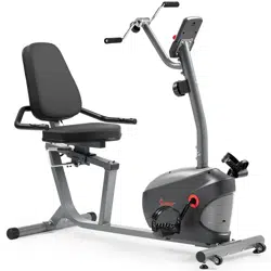
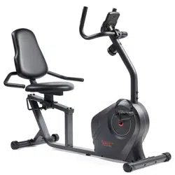
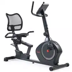
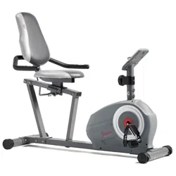
ESSENTIAL INTERACTIVE SERIES
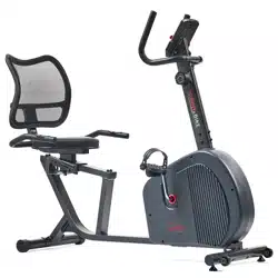
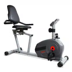
RECUMBENT BIKE
SF-RB422903
USER MANUAL
IMPORTANT! Please retain owner’s manual for maintenance and adjustment instructions.
Your satisfaction is very important to us, PLEASE DO NOT RETURN UNTIL YOU HAVE
CONTACTED US: support@sunnyhealthfitness.com or 1-877-90SUNNY (877-907-8669).

1
IMPORTANT SAFETY INFORMATION
We thank you for choosing our product. To ensure your safety and health, please use this
equipment correctly. It is important to read this entire manual before assembling and using
the equipment. Safe and effective use can only be achieved if the equipment is assembled,
maintained and used properly. It is your responsibility to ensure that all users of the
equipment are informed of all warnings and precautions.
1. Before starting any exercise program, you should consult your physician to determine if
you have any medical or physical conditions that could put your health and safety at risk,
or prevent you from using the equipment properly. Your physician’s advice is essential if
you are taking medication that affects your heart rate, blood pressure or cholesterol level.
2. Be aware of your body’s signals. Incorrect or excessive exercise can damage your health.
Stop exercising if you experience any of the following symptoms: pain, tightness in your
chest, irregular heartbeat, shortness of breath, lightheadedness, dizziness or feelings of
nausea. If you do experience any of these conditions, you should consult your physician
before continuing with your exercise program.
3. Keep children and pets away from the equipment. The equipment is designed for adult
use only.
4. Use the equipment on a solid, flat level surface with a protective cover for your floor or
carpet. To ensure safety, the equipment should have at least 4 feet (1.2 M) of free space
all around it.
5. Ensure that all nuts and bolts are securely tightened before using the equipment. The
safety of the equipment can only be maintained if it is regularly examined for damage
and/or wear and tear.
6. Always use the equipment as indicated. If you find any defective components while
assembling or checking the equipment, or if you hear any unusual noises coming from the
equipment during exercise, discontinue use of the equipment immediately and do not use
until the problem has been rectified.
7. Wear suitable clothing while using the equipment. Avoid wearing loose clothing that may
become entangled in the equipment.
8. Do not place fingers or objects into the moving parts of the equipment
9. The maximum weight capacity of this unit is 220 pounds (100 KG).
10. The equipment is not suitable for therapeutic use.
11. Use caution when lifting and moving the equipment. Always use proper lifting technique
and seek assistance if necessary.
12. Your product is intended for use in cool, dry conditions. You should avoid storage in
extreme cold, hot or damp areas as this may lead to corrosion and other related
problems.
13. This equipment is designed for indoor and home use only! It is not intended for
commercial use!

2
PRE-ASSEMBLY CHECK LIST
.Before you start to assemble, please make sure all parts are included.

3
PARTS LIST
No. Description Spec. Qty. No. Description Spec. Qty.
1
Main Frame
1
28
Tension Controller
1.
2
Handlebar Post
1
34
Seat
1
3
Rear Support Tube
1
49
Backrest
1
4
Slide Rail
1
92
Meter
1
6
Handlebar
1
A
Manual
1
8
Adjustment Handle
1
B
Thank You Card
1
10
Front Stabilizer
1
C
Hardware Package
1
11
Rear Stabilizer
1
D
Battery
2
18L/R
Pedal
1pr.

4
HARDWARE PACKAGE
Ordering Replacement Parts (U.S. and Canadian Customers only)
Please provide the following information in order for us to accurately identify the part(s)
needed:
The model number (found on cover of manual)
The product name (found on cover of manual)
The part number found on the “EXPLODED DIAGRAM” and “PARTS LIST” (found
near the front of the manual)
Please contact us at support@sunnyhealthfitness.com or 1.-.877.-.90SUNNY
(877-907-8669).

5
ASSEMBLY INSTRUCTIONS
We value your experience using Sunny Health and Fitness products. For assistance with parts
or troubleshooting, please contact us at support@sunnyhealthfitness.com or 1-877-90SUNNY
(877-907- 8669).
STEP 1
Remove the 4 preassembled
Carriage Bolts (No. 13), 4 Arc
Washers (No. 14) and 4 Cap Nuts
(No. 15) from 2 Paper Tubes (No.
A) with Spanner (No. 88).
Attach the Front Stabilizer (No. 10)
and the Rear Stabilizer (No. 11) to
the Main Frame (No. 1) with 4
Carriage Bolts (No. 13), 4 Arc
Washers (No. 14) and 4 Cap Nuts
(No. 15) using the
Spanner (No.
88).

6
We value your experience using Sunny Health and Fitness products. For assistance with parts
or troubleshooting, please contact us at support@sunnyhealthfitness.com or 1-877-90SUNNY
(877-907- 8669).
STEP 2
A: Connect the
Pulse Connecting
Wire 1 (No. 23) to the Pulse
Connecting Wire 2 (No. 24) and
connect the Sensor Wire (No. 21) to
the Sensor Connecting Wire (No. 22)
.
I
nsert the Tension Hook (No. 20) from
the Main Frame (No. 1) to the inside
tube of the Handlebar Post (No. 2),
then pull it out of the hole on the
Handlebar Post (No. 2). Finally
connect Tension Hook (No. 20) with
Tension Controller (No. 28) as shown
in Diagram A.
Note: Make sure the Tension
Controller (No. 28)
is at the lowest
level before you connect the cable. This
ensures the wires are at their longest
point. We recommend the assistance of
a second person to help hold the
Handlebar Post (No. 2). This will make
the connection easier when you are
attaching Tension Hook (No. 20) to the
cable.
B: Remove the preassembled Rear
Cover (No. 29), Flat Washer (No. 30)
and Screw (No. 31) from the Tension
Controller (No. 28) with Spanner (No.
88). Lock the Tension Controller (No.
28) to the Handlebar Post (No. 2) with
the Rear Cover (No. 29), Flat Washer
(No. 30) and Screw (No. 31) with the
Spanner (No. 88).
C: Insert the Handlebar Post (No. 2)
into the post of the Main Frame (No.
1); secure with
4
Arc Washers (No.
14) and 4 Screws (No. 27) with the
Allen Wrench (No. 87).
Note: Ensure that all bolts and washers
are in place and partially
threaded in
before completely tightening any of
them.

7
We value your experience using Sunny Health and Fitness products. For assistance with parts
or troubleshooting, please contact us at support@sunnyhealthfitness.com or 1-877-90SUNNY
(877-907-8669).
STEP 3
Connect the
Pulse Connecting
Wire 2 (No. 24) and Pulse
Connecting Wire 3 (No. 25).
Lock the Rear Support Tube (No.
3) to the Main Frame (No. 1) with 2
Hex Socket Pan Head Screws
(No. 36), 4 Flat Washers (No. 35)
and 2 Nylon Nuts (No. 37) with the
Spanner (No. 88) and Allen
Wrench (No. 87). Then cover with
2 Caps (No. 90)
Note:
Do not damage any wires
when locking the
Rear Support
Tube (No. 3) to the Main Frame
(No. 1).
STEP 4
Remove the preassembled 6
Screws (No. 27) and 6 Flat
Washers (No. 35) from the Slide
Rail (No. 4) using the Allen
Wrench (No. 87). Then lo
ck the
Slide Rail (No. 4) to the Rear
Support Tube (No. 3)
and the
Main Frame (No. 1) with 6 Screws
(No. 27) and 6 Flat Washers (No.
35)
that were just removed using
the Allen Wrench (No. 87).
Remove 2 Screws (No. 40) from
the Adjustment Handle (No. 8)
using the Allen Wrench (No. 89),
then lock the Adjustment Handle
(No. 8) to the Adjustment Block
Axle (No. 7) with 2 Screws (No.
40) using the Allen Wrench (No.
89).

8
We value your experience using Sunny Health and Fitness products. For assistance with parts
or troubleshooting, please contact us at support@sunnyhealthfitness.com or 1-877-90SUNNY
(877-907-8669).
STEP 5
Lock the Seat (No. 34) to the Seat
Tube (No. 5) with 4 Screws (No. 27)
and 4 Flat Washers (No. 35) using
the Allen Wrench (No. 87).
Lock the Handlebar (No. 6) to the
Seat Tube (No. 5) with the Carriage
Bolt (No. 51), 2 Flat Washers (No.
35), Screw (No. 27) and Nylon Nut
(No. 37) using the
Allen Wrench
(No. 87) and Spanner (No. 88).
Then cover with the Cap (No. 90).
Connect the
Pulse Connecting
Wire 3 (No. 25) to the Pulse Wire
(No. 26).
Lock the Backrest (No. 49) to the
Seat Tube (No. 5) with 2 Hex
Socket Pan Head Screws (No. 50),
2 Flat Washers (No. 35) using the
Allen Wrench (No. 89).
STEP 6
Attach the Pedals (No. 18L/R) to the
Crank (No. 91) using the Spanner
(No. 88).
NOTE: Make sure to attach Right
Pedal (No. 18R), marked (R), to the
right side of the Crank (No. 91). It
should be tightened clockwise.
Attach the Left Pedal (No. 18L),
marked (L), to the left side of the
Crank (No. 91)
. It should be
tightened counter-clockwise.
Attaching the Pedals (No. 18L/R) to
the wrong Crank (No. 91) or turning
it the wrong direction can damage
the Crank (No. 91).

9
We value your experience using Sunny Health and Fitness products. For assistance with parts
or troubleshooting, please contact us at support@sunnyhealthfitness.com or 1-877-90SUNNY
(877-907-8669).
STEP 7
Remove the preassembled 4 Screws
(No. 32) from the Meter (No. 92) using
the Spanner (No. 88).
Connect the Sensor Connecting Wire
(No. 22) and Pulse Connecting Wire
1 (No. 23)
to the relative wires of
Meter (No. 92), then lock the Meter
(No. 92) to the bracket of Handlebar
Post (No. 2) using 4 Screws (No. 32)
that were just removed with the
Spanner (No. 88).
Note:
To avoid damaging the wires,
please push them into the Handlebar
Post (No. 2) before secure the Meter
(No. 92) onto the bracket.
THE ASSEMBLY IS COMPLETE!

10
ADJUSTMENT GUIDE
ADJUSTING THE SEAT POSITION
To move the Seat (No. 34)
forward or
backward, while seated on the bike, put your
feet on the floor. Shift the Adjustment Handle
(No. 8) down to loosen. Move the Seat (No.
34). Shift the Adjustment Handle (No. 8) up to
secure.
ADJUSTING THE LEVEL
If at any point the bike does not feel level,
you can adjust the Rear End Caps (No.
19).
MOVING THE BIKE
Lift the bike by the Rear Stabilizer (No. 11) until the
wheels on the Front Stabilizer (No. 10) touch the floor.
You can now move the bike to your desired location with
ease.
ADJUSTING THE TENSION
Adjust the tension by rotating the Tension Controller
(No. 28) clockwise
to increase the level of resistance.
Rotate the Tension Controller (No. 28)
counter-clockwise to decrease the level of resistance.
Tension levels are set at Level 1 being the lowest and
Level 8 being the highest.

11
BATTERY INSTALLATION & REPLACEMENT
BATTERY INSTALLATION
1. Take out 2 AAA batteries from computer box.
2. Press the buckle of battery cover on the Meter (No. 92), then remove battery cover.
3. Install 2 AAA batteries into the battery case on the back of the Meter (No. 92). Pay
attention to the battery + and – poles before installing.
4. Press the buckle of battery cover, then put the battery cover back to the back of the Meter
(No. 92).
The installation is complete!
BATTERY REPLACEMENT
1. Press the buckle of battery cover on the back of the Meter (No. 92), then remove battery
cover.
2. Remove the 2 old AAA batteries in the battery case and install 2 new AAA batteries into the
battery case on the back of the Meter (No. 92). Pay attention to the battery + and – poles
before installing.
3. Press the buckle of battery cover, then put the battery cover back to the back of the Meter
(No. 92).
The replacement is complete!
BATTERY DISPOSAL
Dispose the batteries according to the laws and regulations of your local region. Some
batteries may be recycled. When disposing or recycling, do not mix battery types.
Battery
Battery
Cover
92

12
EXERCISE METER
■KEY FUNCTION
This key lets you to select and lock on to a particular
function you want.
SCAN→TIME→SPEED(SPD) →DISTANCE(DIST)
→CALORIES(CAL)→TOTAL DIST(ODO) →RPM
→PULSE
Pressing and hold with 3 seconds to reset the value to
zero(without ODO).
■SLEEP MODE
The system turns off automatically if no activity or keys pressed for approximately 4
minutes.
The system turns on when the MODE key is pressed or activity is signaled.
■FUNCTION
SCAN : Meter will rotate through all functions every 6 seconds.
TIME : Counts the total time from starting to finish.
SPEED: Displays the current speed.
DISTANCE : Counts the distance of an exercise from start to finish.
CALORIE : Counts total calories burned during exercise from start to finish.
TOTAL DIST: Counts the total distance with from start to finish. If the battery is
replaced, the value returns to zero.
RPM: The average number of turns per minute of the wheel to measure the speed of
the pedal.
PULSE : The current pulse rate.
■
SPECIFICATIONS
FUNCTION
SCAN
6S
TIME
0:00-99:59(M :S)
SPEED
0.0~999.9KPH(MPH)
DIST
0.00~999.9KM(MILE)
ODO
0.0~999.9KM(MILE)
CAL
0.0~999.9KCAL
PULSE RATE
40~240BPM
BATTERY
SIZE-AAA, 2PCS
Operating temperature
0~40
℃
(32
℉
-104
℉
)
Storage temperature
-10~60
℃
((14
℉
-140
℉
)

13
APP CONNECTION:
1. Scan the QR code below to download the SunnyFit app onto your mobile device.
2. If this is your first time using the SunnyFit app, follow the in-app instructions to register
for your free SunnyFit account and log in.
3. Ensure that the Bluetooth function is turned on from your mobile device.
4. To connect the equipment to the SunnyFit app:
a. From the “Workout” tab, press on the “Search” button to search for your equipment.
b. Once your equipment appears on the list, tap the “Select” button to confirm.
c. Note: If your equipment does not appear on the "Searching for Equipment" list, check
the METER on your equipment to ensure that it is not in sleep mode and your
phone's Bluetooth function is on, then tap "Retry" to search again.
d. Once your equipment shows up on the “Workout” tab as “Currently Selected”, your
equipment is now ready to display, track, and record your equipment’s workout stats
on the app!
5. If you are unable to replicate these steps, or have any other issues with the SunnyFit
app, please contact SunnyFit support at support@sunnyfit.com, or use the in-app
“Contact Us’ form to request support (“Me” tab -> “Contact Us”).

14
EXPLODED DIAGRAM 1
EXPLODED DIAGRAM 2

15
PARTS LIST
No. Description Spec. Qty. No. Description Spec. Qty.
1 Main Frame 1 46
Cross Pan Head
Self-Drilling Screw
ST3.5x8 4
2
Handlebar Post
1
47
Bushing
2
3
Rear Support Tube
1
48
Square Bushing
2
4
Slide Rail
1
49
Backrest
1
5 Seat Tube 1 50
Hex Socket Pan
Head Screw
M8x50 2
6
Handlebar
1
51
Carriage Bolt
M8x60
1
7
Adjustment Block Axle
1
52
Foam Grip
2
8
Adjustment Handle
1
53
Wire Plug
2
9
Fixed Plate 3
1
54
Pulse Plate
2
10
Front Stabilizer
1
55
Round Plug
2
11
Rear Stabilizer
1
56
Crank Cover
2
12
Refer to #91
-
57L/R
Chain Cover
1pr.
13
Carriage Bolt
M8xL74
4
58
Nut
2
14 Arc Washer
Ф8.5x1.5xФ25x
R33.5
8 59 Washer 1
15
Cap Nut
M8
4
60
Two-Slot Nut
1
16L/R
Front End Cap
1pr.
61
Ball Rack
2
17
Cross Pan Head
Self-Drilling Screw
ST4.2x18 11 62 Axle Bowl 2
18L/R
Pedal 1pr. 63
Hex Socket Pan
Head Screw
ST5x20 4
19
Rear End Cap
2
64
Square Plug
80x40x1.5
1
20
Tension Hook
1
65
Three-Slot Nut
1
21
Sensor Wire
1
66
Big Flat Washer
1
22
Sensor Connecting
Wire
1 67 Belt 1
23
Pulse Connecting Wire
1
1 68 Belt Pulley 1
24
Pulse Connecting Wire
2
1 69 Hex Bolt M5x60 1
25
Pulse Connecting Wire
3
1 70 Hex Screw M5 2
26
Pulse Wire
1
71
Hex Bolt
M6xL15
2
27
Screw
M8x16
15
72
Spring Washer
Ф6
2
28
Tension Controller
1.
73
Flat Washer
D6
2
29
Rear Cover
1
74
Conical Thin Nut
M10x1
2
30
Flat Washer
1
75
Magnetic Board Axle
1
31
Screw
1
76
Magnetic Board
1
32
Screw
4
77
Tension Spring
1
33
Refer to #92
-
78
Square Magnet
8
34
Seat
1
79
Flange Nut
M10x1
2
35 Flat Washer D8x1.5xФ16 18 80
Adjustment Chain
Bolt
M6x50 2
36
Hex Socket Pan Head
Screw
M8x100 2 81
Adjustment Chain U
Mat
2
37
Nylon Nut
M8
3
82
Hex Screw
M6
2
38
Square Cap
2
83
Flywheel
1
39
Fixed Handlebar Glove
1
84
Bearing
6000
2
40
Screw
M6x10
2
85
Flywheel Axle
1
41
Screw
M6x16
2
86
Square Plug
50x25x1.5
1
42
Eccentric Wheel
1
87
Allen Wrench
S6
1
43
Screw
M8x10
1
88
Spanner
S13,S14,S15
1
44
Upper Block
1
89
Allen Wrench
S5
1
45
Axle Spring Washer
D12
3
90
Cap
S13
3
91
Crank
1
92
Meter
1
Version 1.0