OWNER'S
MANUAL
MODEL NO.
944.524593
CRRFT$1VlRH°
Caution:
Read and follow
all Safety Rules
and Instructions
Before Operating
This Equipment
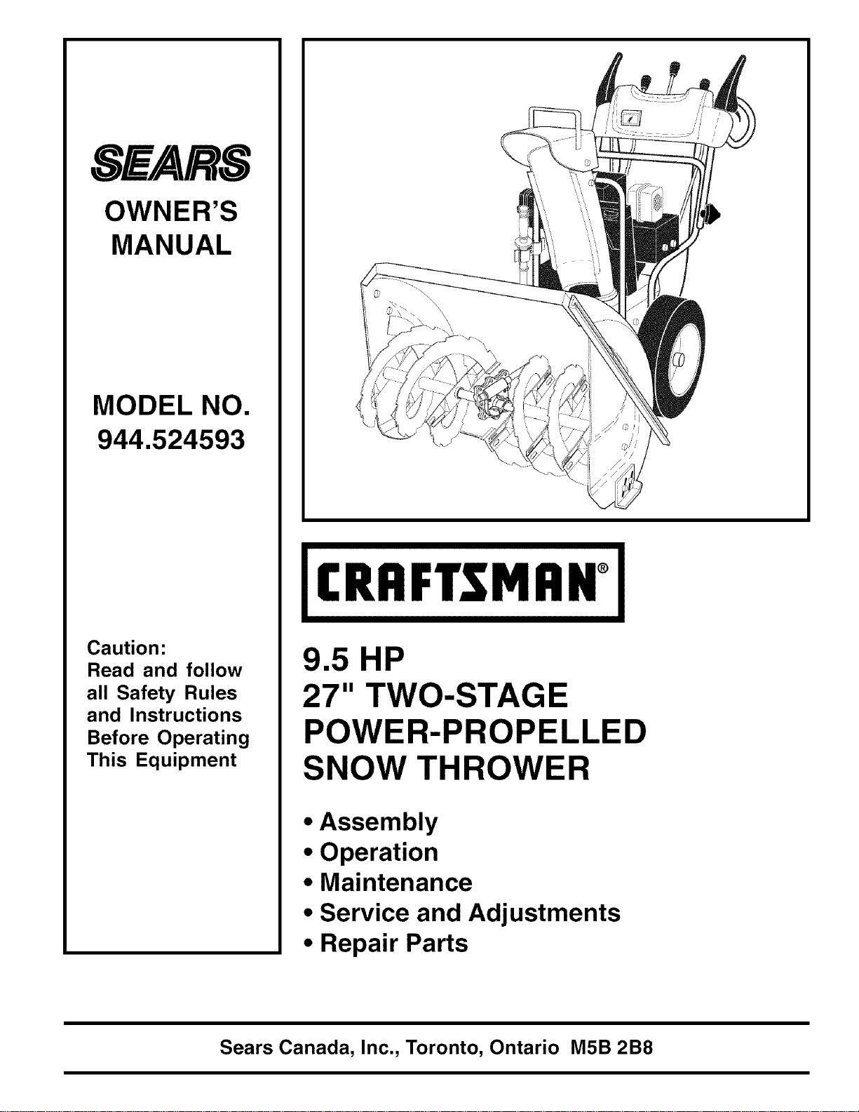
9.5 HP
27" TWO-STAGE
POWER-PROPELLED
SNOW THROWER
• Assembly
• Operation
• Maintenance
• Service and Adjustments
• Repair Parts
Sears Canada, Inc., Toronto, Ontario M5B 2B8
IMPORTANT
Safe Operation Practices for Walk-Behind Snow Throwers
This snow thrower is capable of amputating hands and feet and throwing objects.
Failure to observe the following safety instructions could result in serious injury.
Look for this symbol to point out im-
portant safety precautions. It means
CAUTION!!! BECOMEALERT!!! YOUR
SAFETY IS INVOLVED.
WARNING: Always disconnect spark
plug wire and place it where it cannot
contact plug in order to prevent acci-
dental starting when setting up, trans-
porting, adjusting or making repairs.
WARNING: This snow thrower is for
use on sidewalks, driveways and other
ground level surfaces. Caution should
be exercised while using on sloping
surfaces. Do not use snowthrower on
surfaces above ground level such as
roofs of residences, garages, porches
or other such structures or buildings.
&
&
WARNING: Snow throwers have ex-
posed rotating parts, which can cause
severe injury from contact, or from ma-
terial thrown from the discharge chute.
Keep the area of operation clear of all
persons, small children and pets at all
times including startup.
CAUTION: Muffler and other engine
parts become extremely hot during
operation and remain hot after engine
has stopped. To avoid severe burns on
contact, stay away from these areas.
WARNING: Engine exhaust, some of
its constituents, and certain vehicle
components contain or emit chemi-
cals known to the State of California
to cause cancer and birth defects or
other reproductive harm.
Training
1. Read, understand and follow all instructions on the
machine and in the manual(s) before operating this
unit. Be thoroughly familiar with the controls and the
proper use of the equipment. Know how to stop the
unit and disengage the controls quickly.
2. Never allow children to operate the equipment. Never
allow adults to operate the equipment without proper
instruction.
3. Keep the area of operation clear of all persons, par-
ticularly small children.
4. Exercise caution to avoid slipping or falling, especially
when operating the snow thrower in reverse.
Preparation
1. Thoroughly inspect the area where the equipment is
to be used and remove all doormats, sleds, boards,
wires, and other foreign objects.
2. Disengage all clutches and shift into neutral before
starting the engine (motor).
3. Do notoperate the equipment without wearing adequate
winter garments. Avoid loose fitting clothing that can
get caught in moving parts. Wear footwear that will
improve footing on slippery surfaces.
4. Handle fuel with care; it is highly flammable
(a) Use an approved fuel container.
(b) Never add fuel to a running engine or hot en-
gine.
(c) Fill fuel tank outdoors with extreme care. Never fill
fuel tank indoors.
(d) Neverfill containers inside a vehicle oron a truck or
trailer bed with aplastic liner. Always place contain-
ers on the ground, away from your vehicle, before
filling.
(e) When practical, remove gas-powered equipment
from the truck or trailer and refuel it on the ground.
If this is not possible, then refuel such equipment
on a trailer with a portable container, rather than
from a gasoline dispenser nozzle.
5,
6,
7.
8,
(f) Keep the nozzle in contact with the rim of the fuel
tank or container opening at all times, until refuel-
ing is complete. Do not use a nozzle lock-open
device.
(g) Replace gasoline cap securely and wipe up spilled
fuel.
(h) If fuel is spilled on clothing, change clothing im-
mediately.
Use extension cords and receptacles as specified by
the manufacturer for all units with electric drive motors
or electric starting motors.
Adjust the collector housing height to clear gravel or
crushed rock surface.
Never attempt to make any adjustments while the
engine (motor) is running (except when specifically
recommended by manufacturer).
Always wear safety glasses or eye shields during op-
eration or while performing an adjustment or repair to
protect eyes from foreign objects that may be thrown
from the machine.
Operation
1. Do not put hands or feet near or under rotating parts.
Keep clear of the discharge opening at all times.
2. Exercise extreme caution when operating on or cross-
ing gravel drives, walks, or roads. Stay alert for hidden
hazards or traffic.
3. After striking a foreign object, stop the engine (motor),
remove the wire from the spark plug, disconnect the
cord on electric motors, thoroughly inspect the snow
thrower for any damage, and repair the damage before
restarting and operating the snow thrower.
4. If the unit should start to vibrate abnormally, stop the
engine (motor) and check immediately for the cause.
Vibration is generally a warning of trouble.
5. Stop the engine (motor) whenever you leave the oper-
ating position, before unclogging the collector/impeller
housing or discharge chute, and when making any
repairs, adjustments or inspections.
6. Whencleaning,repairingor inspectingthe snow
thrower,stoptheengineandmakecertainthecollector/
impellerandallmovingpartshavestopped.Disconnect
thesparkplugwireandkeepthewireawayfromthe
plugtopreventsomeonefromaccidentallystartingthe
engine.
7. Donotruntheengineindoors,exceptwhenstarting
theengineandfortransportingthesnowthrowerinor
outofthebuilding.Opentheoutsidedoors;exhaust
fumesaredangerous.
8. Exerciseextremecautionwhenoperatingonslopes.
9. Neveroperatethesnowthrowerwithoutproperguards,
andothersafetyprotectivedevicesinplaceandwork-
ing.
10.Neverdirectthedischargetowardpeopleorareas
wherepropertydamagecanoccur.Keepchildrenand
othersaway.
11.Donotoverloadthemachinecapacitybyattempting
toclearsnowattoofastarate.
12.Neveroperatethemachineathightransportspeeds
onslipperysurfaces.Lookbehindandusecarewhen
operatinginreverse.
13.Disengagepowertothecollector/impellerwhensnow
throweristransportedornotinuse.
14.Useonlyattachmentsandaccessoriesapprovedby
themanufacturerofthesnowthrower(suchaswheel
weights,counterweights,orcabs).
15.Neveroperatethesnowthrowerwithoutgoodvisibility
orlight.Alwaysbesureofyourfooting,andkeepa
firmholdonthehandles.Walk;neverrun.
16.Nevertouchahotengineormuffler.
Clearing a Clogged Discharge Chute
Hand contact with the rotating impeller inside the discharge
chute is the most common cause of injury associated with
snow throwers. Never use your hand to clean out the dis-
charge chute. To clear the chute:
1. SHUT THE ENGINE OFF!
2. Wait 10 seconds to be sure the impeller blades have
stopped rotating.
3. Always use a clean-out tool, not your hands.
Maintenance and Storage
1. Check shear bolts and other bolts at frequent intervals
for proper tightness to be sure the equipment is in safe
working condition.
2. Never store the machine with fuel in the fuel tank
inside a building where ignition sources are present
such as hot water heaters, space heaters, or clothes
dryers. Allow the engine to cool before storing in any
enclosure.
3. Always refer to operator's manual for important details
if the snow thrower is to be stored for an extended
period.
4. Maintain or replace safety and instruction labels, as
necessary.
5. Run the machine a few minutes after throwing snow
to prevent freeze-up of the collector/impeller.
TABLE OF CONTENTS
SAFETY RULES ........................................................ 2-3
PRODUCT SPECIFICATIONS ...................................... 4
CUSTOMER RESPONSIBILITIES ................................ 4
WARRANTY .................................................................. 4
ASSEMBLY / PRE-OPERATION ............................... 6-8
OPERATION ............................................................ 9-15
MAINTENANCE ..................................................... 15-16
MAINTENANCE SCHEDULE ..................................... 15
SERVICE AND ADJUSTMENTS ........................... 17-19
STORAGE ................................................................... 19
TROUBLESHOOTING ................................................ 20
REPAIR PARTS ..................................................... 22-38
SEARS SERVICE ................................... BACK COVER
LIMITED TWO (2) YEAR WARRANTY ON CRAFTSMAN SNOW THROWER
For two (2) years from date of purchase Sears Canada, Inc. will repair or replace, at Sears option, free of charge
parts which are defective as a result of material or workmanship.
COMMERCIAL OR RENTAL USE:
Warranty on Snow Thrower will be 90 days from date of purchase if used for commercial or rental purposes.
This Warranty does NOT cover:
1. Pre-delivery set-up.
2. Expendable items which become worn during normal use, such as belts, spark plugs, air cleaners,
and shear pins, as well damage to the engine resulting from operating snow thrower with insufficient oil.
3. Repairs necessary because of operator abuse or negligence, including the failure to operate and main-
tain the equipment according to the instructions contained in the Owner's Manual.
4. Tire replacement or repair caused by punctures from outside objects, such as nails, thorns, stumps or glass.
Warranty service is available by returning the Craftsman Snow Thrower tothe nearest Sears Service Centre/Department
in Canada. This warranty applies only while this product is in use in Canada.
This warranty is in addition to any statutory warranty and does NOT exclude or limit legal rights you may have but
shalll run concurrently with applicable provincial legislation. Furthermore, some provinces do not allow limitations
on how long an implied warranty will last, so the above limitations may not apply to you.
Sears Canada, Inc., Toronto, Ontario M5B 2B8
CONGRATULATIONS on your purchase of a new snow
thrower. Ithas been designed, engineered and manufactured
to give best possible dependability and performance.
Should you experience any problem you cannot easily
remedy, please contact your nearest Sears service centre/
department. We have competent, well-trained technicians
and the proper tools to service or repair this unit.
Please read and retain this manual. The instructions will
enable you to assemble and maintain your snow thrower
properly. Always observe the "SAFETY RULES".
SERIAL NUMBER:
DATE OF PURCHASE:
THE MODELAND SERIAL NUMBERS WILL BE FOUND
ON A DECALATTACH EDTO THE REAR OFTHE SNOW
THROWER HOUSING.
YOU SHOULD RECORD BOTH SERIAL NUMBERAND
DATE OF PURCHASE AND KEEP IN A SAFE PLACE
FOR FUTURE REFERENCE.
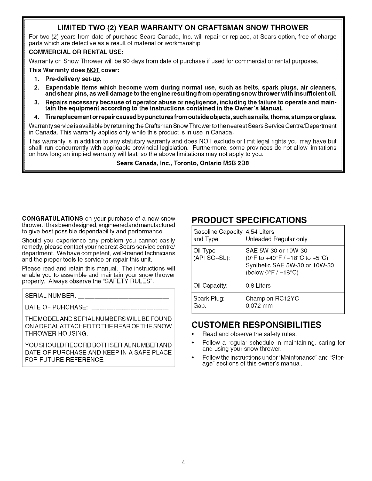
PRODUCT SPECIFICATIONS
Gasoline Capacity 4,54 Liters
and Type: Unleaded Regular only
Oil Type SAE 5W-30 or 10W-30
(API SG-SL): (O°Fto +40°F/-18°C to +5°C)
Synthetic SAE 5W-30 or 10W-30
(below O°F/-18°C)
Oil Capacity: 0,8 Liters
Spark Plug: Champion RC12YC
Gap: 0,072 mm
CUSTOMER RESPONSIBILITIES
• Read and observe the safety rules.
• Follow a regular schedule in maintaining, caring for
and using your snow thrower.
• Follow the instructions under"Maintenance" and "Stor-
age" sections of this owner's manual.

PARTS PACKED SEPARATELY IN CARTON
(1) POWER
CORD
(1) DISCHARGE CHUTE
(1) FUEL STABiLiZER PACKET
START
(2) SAFETY iGNiTiON KEYS
(1) AUGER CONTROL ROD
(1) TRACTION DRIVE CONTROL ROD
(1) MULTi=
WRENCH
EXTRA SHEAR BOLTS AND NUTS
(2) SHOULDER BOLTS
1/4=20 × 2 (AUGER SHAFT)
©
(2) LOCKNUTS
1/4-20
ROTATOR HEAD MOUNTING
(1) WASHER 3/8
(1) LOCKNUT 3/8
I
I
I
I
I
J
(3) RETAINER
SPRINGS
(1) LOCKNUT
5/16=18
(1) CARRIAGE
BOLT 5/16-18 x 5/8
CHUTE DEFLECTOR REMOTE CONTROL
(1) LOCKNUT (1) NYLON
1/4=20 WASHER
(1) SHOULDER
BOLT 1/4=20 (1) SPRING
ASSEMBLY / PRE-OPERATION
Read these instructions and this manual in its entirety
before you attempt to assemble or operate your new
snowthrower. Reading the entire manual will familiar-
ize you with the unit, which will assist you in assembly,
operation and maintenance of the product.
Your new snow thrower has been assembled at the factory
with the exception of those parts left unassembled for ship-
ping purposes. All parts such as nuts, washers, bolts, etc.,
necessary to complete the assembly have been placed in
the parts bag. To ensure safe and proper operation of your
snow thrower, all parts and hardware you assemble must
be tightened securely. Use the correct tools as necessary
to ensure proper tightness.
REMOVE SNOW THROWER FROM CARTON
1. Remove all accessible loose parts and parts boxes
from carton.
2. Cut down all four corners of carton and lay panels flat.
3. Remove the two (2) screws securing the auger housing
to the pallet.
4. Remove all packing materials except plastic tie holding
speed control rod to lower handle.
5. Remove the two (2) plastic ties securing the upper
handle to the pallet.
6. Remove snow thrower from carton and check carton
thoroughly for additional loose parts.
HOW TO SET UP YOUR SNOW THROWER
TOOL BOX (See Fig. 10)
A toolbox is provided on your snow thrower. The toolbox is
located on top of the belt cover. Store the extra shear bolts,
nuts and multi-wrench provided in parts bag in the toolbox.
NOTE: The multi-wrench may be used for assembly of the
chute rotator head tosnowthrower and making adjustments
to the skid plates.
UNFOLD UPPER HANDLE
1. Raise upper handle tothe operating position and tighten
handle knobs securely.
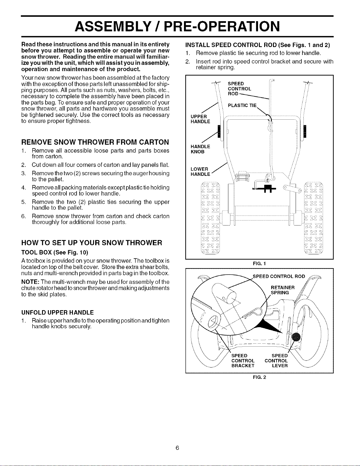
INSTALL SPEED CONTROL ROD (See Figs. 1 and 2)
1. Remove plastic tie securing rod to lower handle.
2. Insert rod into speed control bracket and secure with
retainer spring.
SPEED
",,",,, CONTROL
/
/
/ /
i / /
PLASTIC TIE
UPPER
HANDLE
HANDLE
KNOB
LOWER
HANDLE
i
FIG. 1
SPEED CONTROL ROD
RETAINER
SPRING
SPEED SPEED
CONTROL CONTROL
BRACKET LEVER
FIG. 2
ASSEMBLY / PRE-OPERATION
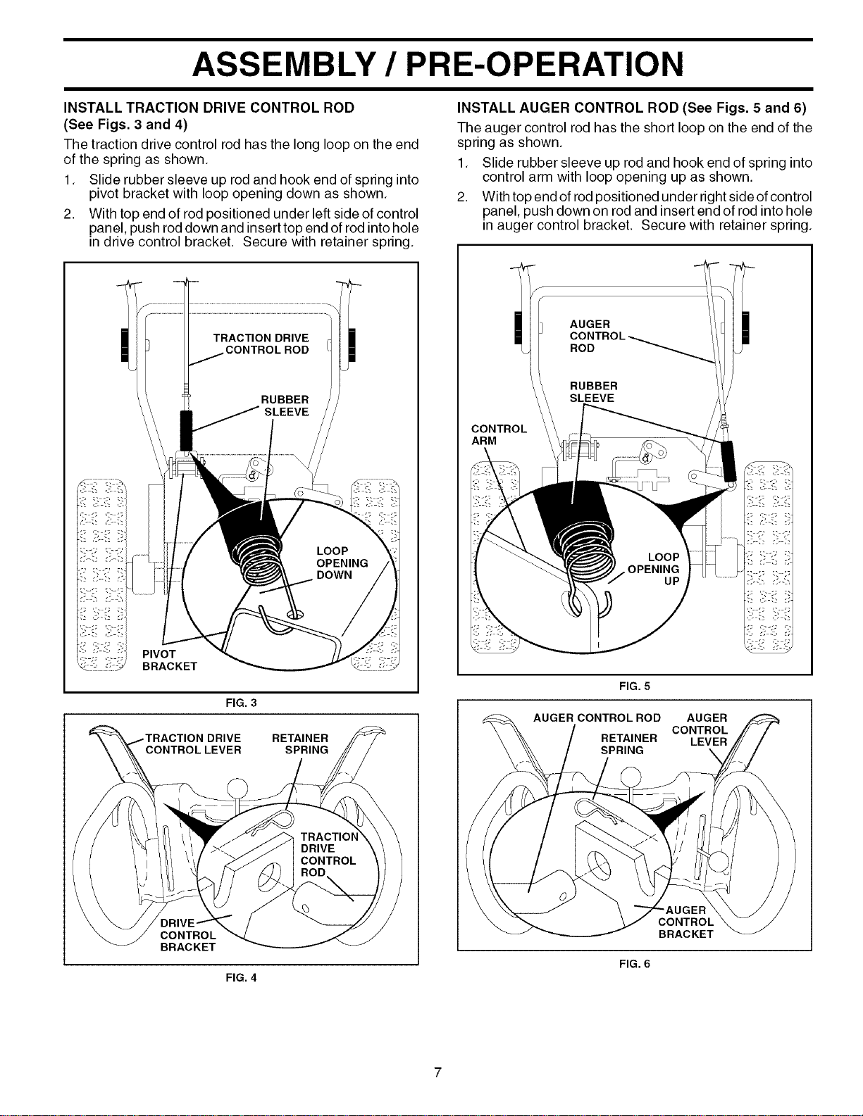
INSTALL TRACTION DRIVE CONTROL ROD
(See Figs. 3 and 4)
The traction drive control rod has the long loop on the end
of the spring as shown.
1. Slide rubber sleeve up rod and hook end of spring into
pivot bracket with loop opening down as shown.
2. With top end of rod positioned under left side of control
panel, push rod down and insert top end of rod into hole
in drive control bracket. Secure with retainer spring.
PIVOT
BRACKET
FIG. 3
RETAINER
SPRING
CONTROL
BRACKET
FIG. 4
INSTALL AUGER CONTROL ROD (See Figs. 5 and 6)
The auger control rod has the short loop on the end of the
spring as shown.
1. Slide rubber sleeve up rod and hook end of spring into
control arm with loop opening up as shown.
2. With top end of rodpositioned under right side of control
panel, push down on rod and insert end of rod into hole
in auger control bracket. Secure with retainer spring.
CONTROL
ARM
FIG. 5
AUGER CONTROL ROD AUGER
CONTROL
RETAINER LEVER
SPRING \
CONTROL
BRACKET
FIG. 6
ASSEMBLY / PRE-OPERATION
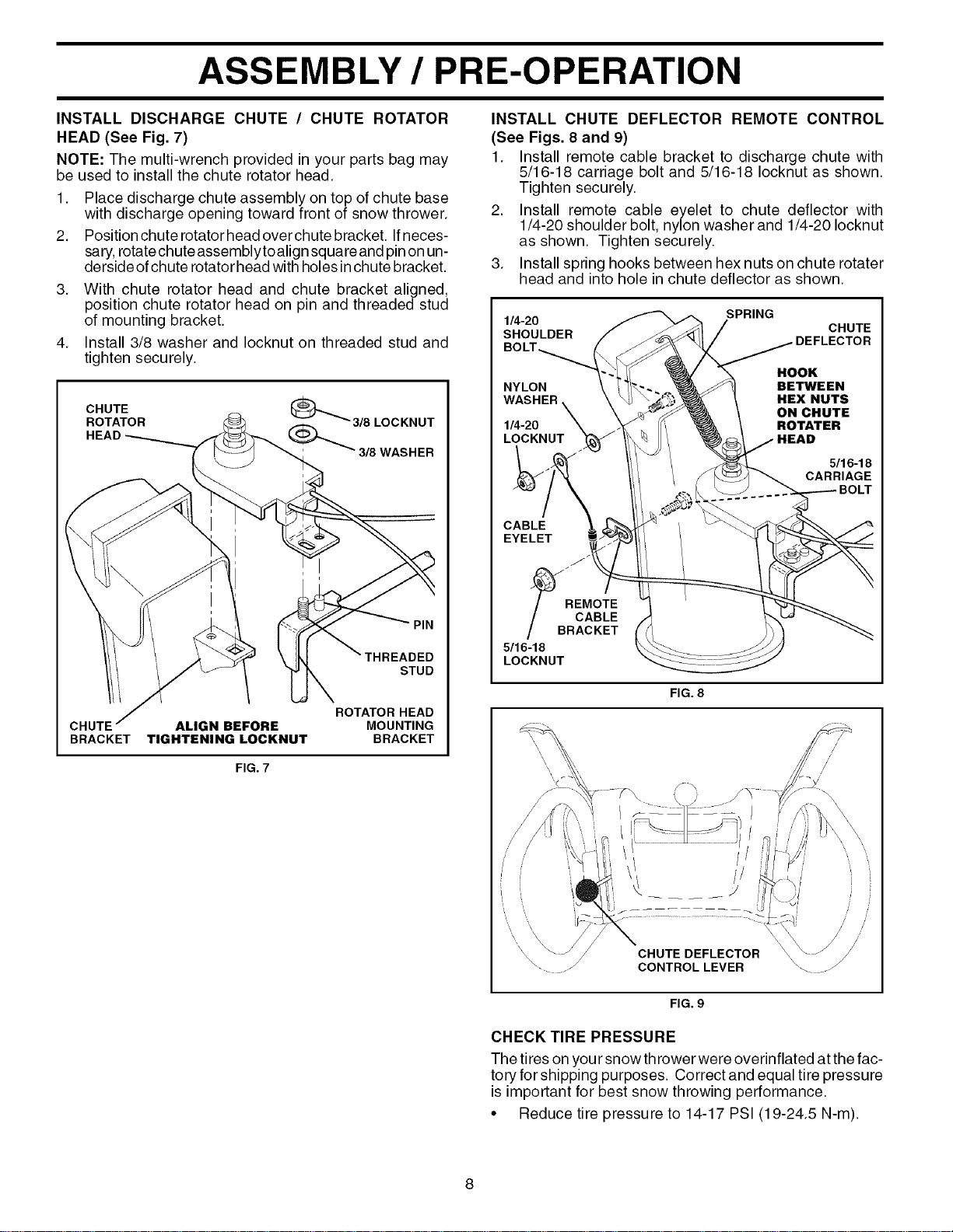
INSTALL DISCHARGE CHUTE / CHUTE ROTATOR
HEAD (See Fig. 7)
NOTE: The multi-wrench provided in your parts bag may
be used to install the chute rotator head.
1. Place discharge chute assembly on top of chute base
with discharge opening toward front of snow thrower.
2. Position chute rotator head overchute bracket. Ifneces-
sary, rotate chute assemblytoalign square and pinon un-
derside of chute rotator head with holes in chute bracket.
3. With chute rotator head and chute bracket aligned,
position chute rotator head on pin and threaded stud
of mounting bracket.
4. Install 3/8 washer and Iocknut on threaded stud and
tighten securely.
CHUTE
ROTATOR
PIN
STUD
ROTATOR HEAD
CHUTE ALIGN BEFORE MOUNTING
BRACKET TIGHTENING LOCKNUT BRACKET
FIG. 7
INSTALL CHUTE DEFLECTOR REMOTE CONTROL
(See Figs. 8 and 9)
1. Install remote cable bracket to discharge chute with
5/16-18 carriage bolt and 5/16-18 Iocknut as shown.
Tighten securely.
2. Install remote cable eyelet to chute deflector with
1/4-20 shoulder bolt, nylon washer and 1/4-20 Iocknut
as shown. Tighten securely.
3. Install spring hooks between hex nuts on chute rotater
head and into hole in chute deflector as shown.
SPRING
1/4-20
SHOULDER CHUTE
HOOK
NYLON BETWEEN
WASHER HEX NUTS
ON CHUTE
1/4-20 ROTATER
LOCKNUT
CABLE
EYELET
5/16-18
CARRIAGE
BOLT
J
_B _EMoTE
CABLE
RAC KET
5/16-18
LOCKNUT
FIG. 8
\\
CHUTE DEFLECTOR
CONTROL LEVER
/i iii
FIG. 9
CHECK TIRE PRESSURE
The tires on your snowthrower were overinflated at the fac-
tory for shipping purposes. Correct and equal tire pressure
is important for best snow throwing performance.
• Reduce tire pressure to 14-17 PSI (19-24.5 N-m).
OPERATION
KNOW YOUR SNOW THROWER
READ THIS OWNER'S MANUAL AND ALL SAFETY RULES BEFORE OPERATING YOUR SNOW THROWER. Compare
the illustrations with your snow thrower to familiarize yourself with the location of various controls and adjustments. Save
this manual for future reference.
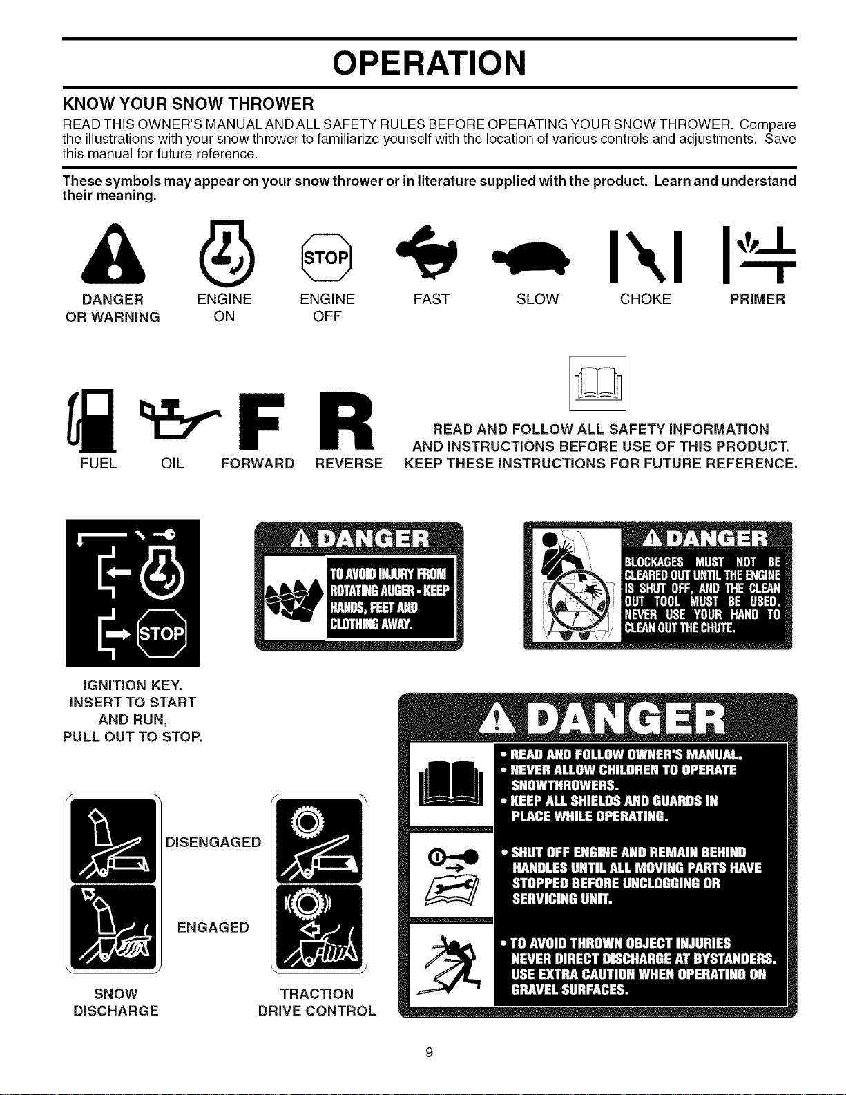
These symbols may appear on your snow thrower or in literature supplied with the product. Learn and understand
their meaning.
ENGINE
OFF
DANGER ENGINE FAST SLOW CHOKE PRIMER
OR WARNING ON
R
FUEL OIL FORWARD REVERSE
READ AND FOLLOW ALL SAFETY iNFORMATiON
AND iNSTRUCTIONS BEFORE USE OF THiS PRODUCT.
KEEP THESE iNSTRUCTiONS FOR FUTURE REFERENCE.
iGNiTiON KEY.
iNSERT TO START
AND RUN,
PULL OUT TO STOP.
DISENGAGED
ENGAGED
\ J
SNOW
DISCHARGE
TRACTION
DRIVECONTROL
OPERATION
GASOLINE
CHOKE
CON-
TROL
ELECTRIC AUGER
START CONTROL
BUTTON LEVER DRIVE SPEED
RECOIL X_ONTROL LEVER
(AUXILIARY)
STARTER
HANDLE
CHUTE
DEFLECTOR
DISCHARGE CHUTE CONTROL LEVER
DEFLECTOR REMOTE
CONTROL LEVER
'TRACTION
DRIVE
CONTROL
LEVER
SAFETY
IGNITION
KEY FUEL
SHUT-OFF
VALVE
NOTE: ITEMS ABOVE
ARE SHOWN IN
THEIR TYPICAL
LOCATION ON THE
ENGINE. ACTUAL
LOCATION MAY VARY
WITH THE ENGINE
ON YOUR UNIT.
THROTTLE
/ ENGINE
CONTROL
CHUTE
CLEAN-OUTTOOL
\ \
\
.H TURN
TRIGGER
LIGHT
HANDLE
KNOB
TOOLBOX
SKID PLATE
FIG. 10
MEETS A.N.S.I. SAFETY REQUIREMENTS
Our snow throwers conform to the standards of the American National Standards Institute.
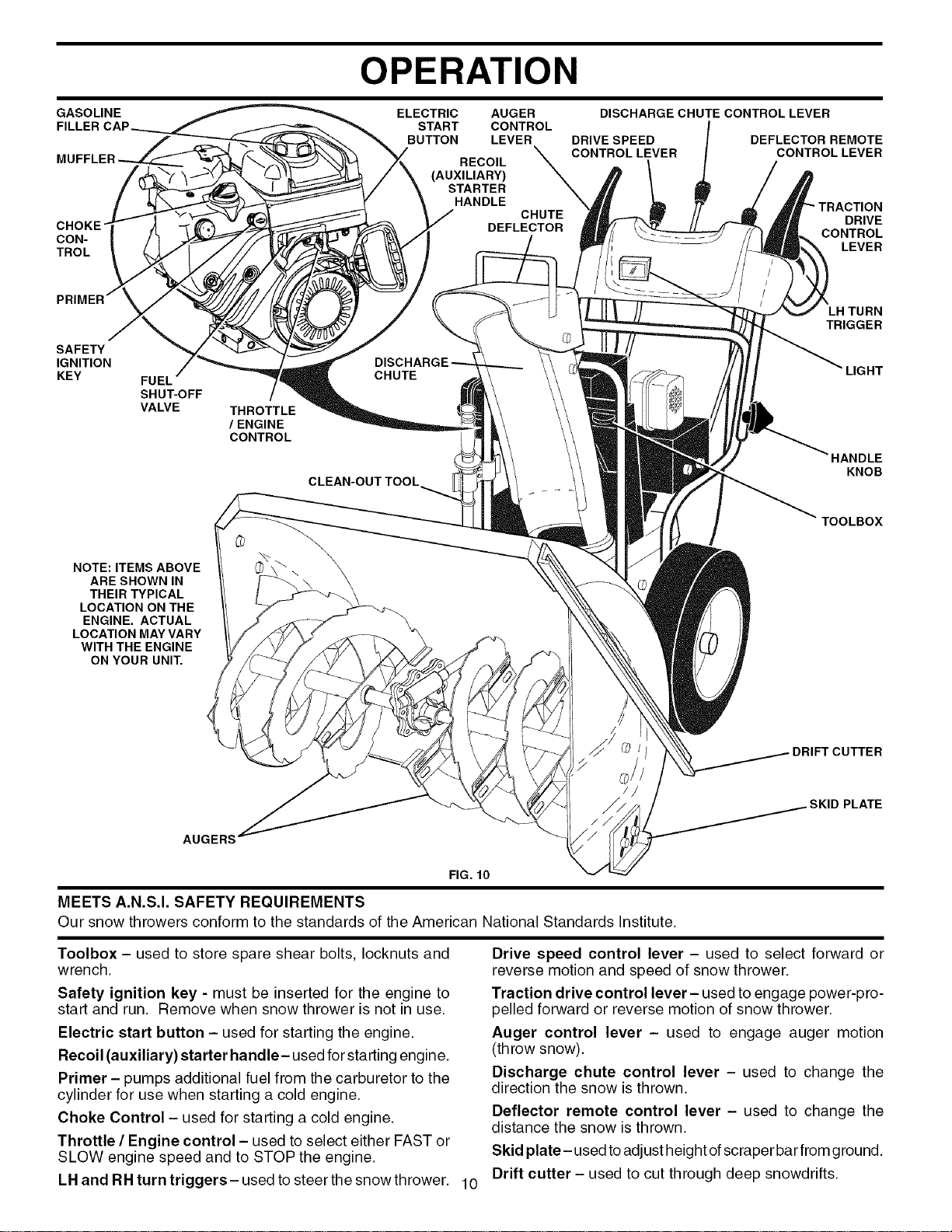
Toolbox - used to store spare shear bolts, Iocknuts and
wrench.
Safety ignition key - must be inserted for the engine to
start and run. Remove when snow thrower is not in use.
Electric start button - used for starting the engine.
Recoil (auxiliary) starter handle- used for starting engine.
Primer - pumps additional fuel from the carburetor to the
cylinder for use when starting a cold engine.
Choke Control - used for starting a cold engine.
Throttle / Engine control - used to select either FAST or
SLOW engine speed and to STOP the engine.
LH and RH turn triggers- used to steer the snow thrower. 10
Drive speed control lever - used to select forward or
reverse motion and speed of snow thrower.
Traction drive control lever- used to engage power-pro-
pelled forward or reverse motion of snow thrower.
Auger control lever - used to engage auger motion
(throw snow).
Discharge chute control lever - used to change the
direction the snow is thrown.
Deflector remote control lever - used to change the
distance the snow is thrown.
Skid plate- used toadjust height of scraper bar from ground.
Drift cutter - used to cut through deep snowdrifts.
OPERATION
The operation of any snow thrower can result
in foreign objects thrown into the eyes, which
can result insevere eye damage. Always wear
safety glasses or eye shields while operating
your snow thrower or performing any adjust-
ments or repairs. We recommend standard safety glasses
or a wide vision safety mask worn over spectacles.
HOW TO USE YOUR SNOW THROWER
Know how to operate all controls before adding fuel or
attempting to start the engine.
STOPPING
TRACTION DRIVE
• Release traction drive control lever to stop the forward
or reverse movement of the snow thrower.
AUGER
• Release the auger control lever to stop throwing snow.
ENGINE
1. Move throttle control to "STOP" position.
2. Remove (do not turn) safety ignition key to prevent
unauthorized use.
NOTE: Never use choke to stop engine.
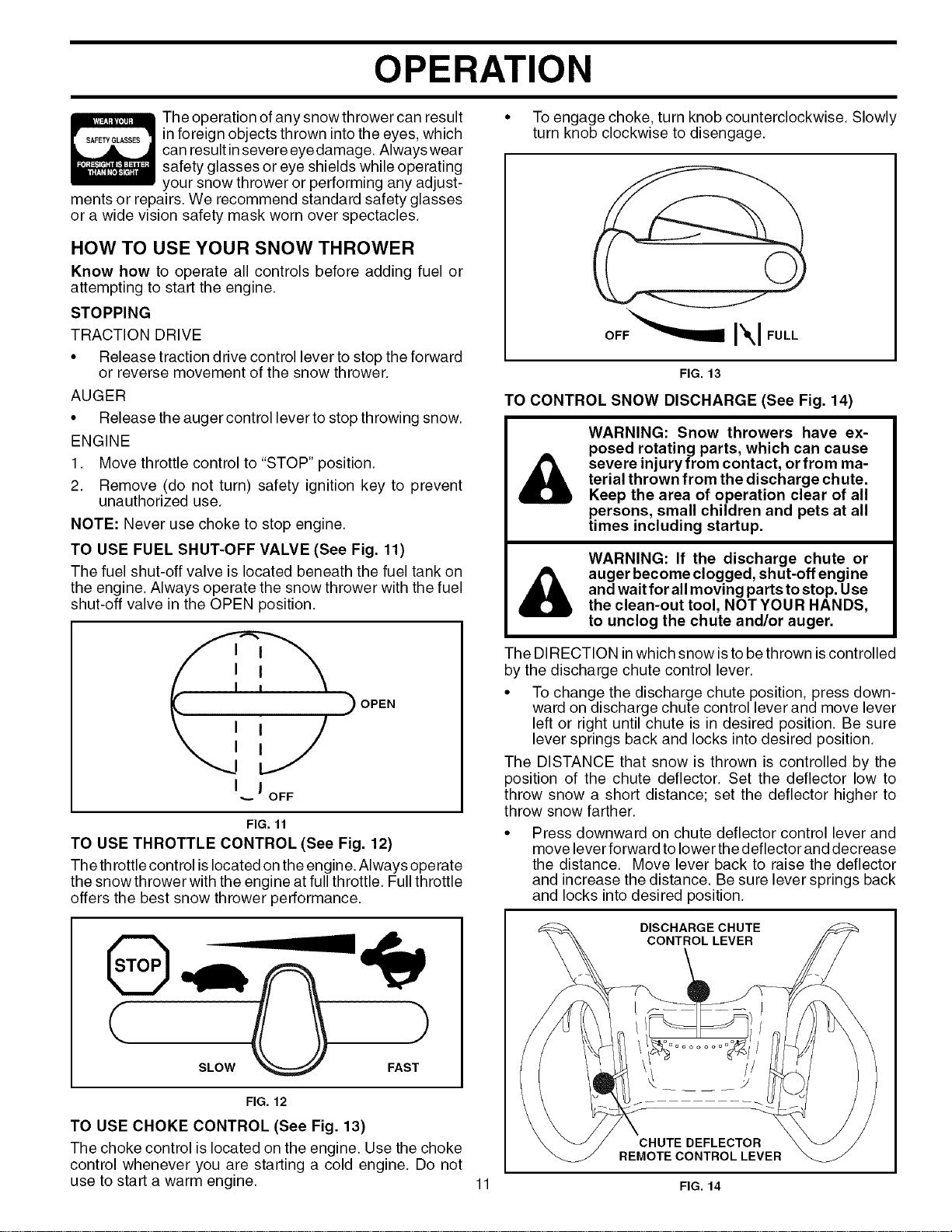
TO USE FUEL SHUT-OFF VALVE (See Fig. 11)
The fuel shut-off valve is located beneath the fuel tank on
the engine. Always operate the snow thrower with the fuel
shut-off valve in the OPEN position.
I I
I J
•... OFF
OPEN
FIG. 11
TO USE THROTTLE CONTROL (See Fig. 12)
The throttle control is located on the engine. Always operate
the snowthrower with the engine at full throttle. Full throttle
offers the best snow thrower performance.
FIG. 12
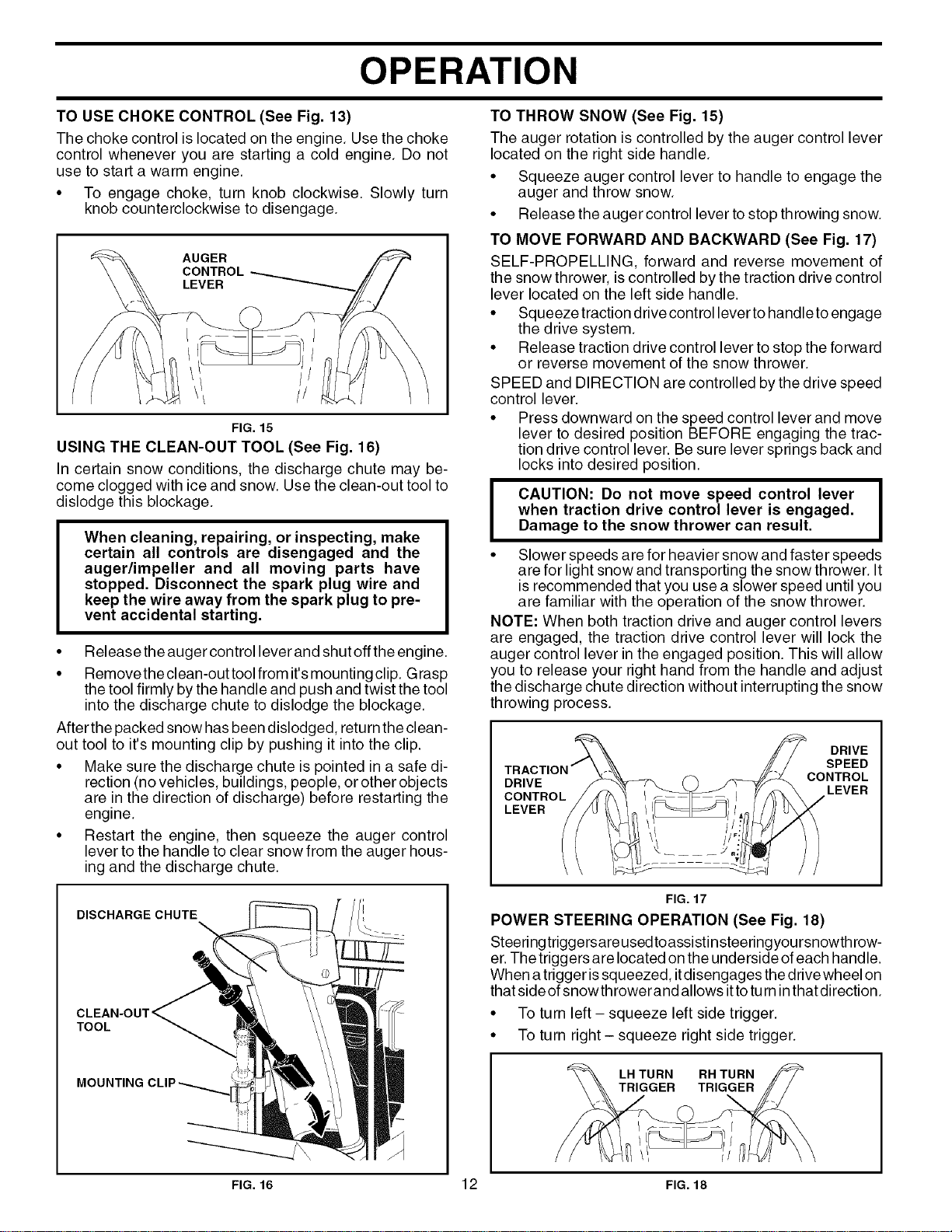
TO USE CHOKE CONTROL (See Fig. 13)
The choke control is located on the engine. Use the choke
control whenever you are starting a cold engine. Do not
use to start a warm engine.
• To engage choke, turn knob counterclockwise. Slowly
turn knob clockwise to disengage.
FIG. 13
TO CONTROL SNOW DISCHARGE (See Fig. 14)
&
WARNING: Snow throwers have ex-
posed rotating parts, which can cause
severe injury from contact, or from ma-
terial thrown from the discharge chute.
Keep the area of operation clear of all
persons, small children and pets at all
times including startup.
WARNING: If the discharge chute or
auger become clogged, shut-off engine
and wait for all moving parts to stop. Use
the clean-out tool, NOT YOU R HANDS,
to unclog the chute and/or auger.
The DIRECTION inwhich snow is to be thrown iscontrolled
by the discharge chute control lever.
• To change the discharge chute position, press down-
ward on discharge chute control lever and move lever
left or right until chute is in desired position. Be sure
lever springs back and locks into desired position.
The DISTANCE that snow is thrown is controlled by the
position of the chute deflector. Set the deflector low to
throw snow a short distance; set the deflector higher to
throw snow farther.
Press downward on chute deflector control lever and
move lever forward to lower the deflector and decrease
the distance. Move lever back to raise the deflector
and increase the distance. Be sure lever springs back
and locks into desired position.
DlSCHARGECHUTE
CONTROL LEVER
ooooooooO'
CHUTE DEFLECTOR
REMOTE CONTROL LEVER
11 FIG. 14
OPERATION
TO USE CHOKE CONTROL (See Fig. 13)
The choke control is located on the engine. Use the choke
control whenever you are starting a cold engine. Do not
use to start a warm engine.
• To engage choke, turn knob clockwise. Slowly turn
knob counterclockwise to disengage.
FIG. 15
USING THE CLEAN-OUT TOOL (See Fig. 16)
In certain snow conditions, the discharge chute may be-
come clogged with ice and snow. Use the clean-out tool to
dislodge this blockage.
When cleaning, repairing, or inspecting, make
certain all controls are disengaged and the
auger/impeller and all moving parts have
stopped. Disconnect the spark plug wire and
keep the wire away from the spark plug to pre-
vent accidental starting.
• Release the auger control lever and shut off the engine.
• Removethe clean-out tool from it'smounting clip. Grasp
the tool firmly by the handle and push and twist the tool
into the discharge chute to dislodge the blockage.
After the packed snow has been dislodged, return the clean-
out tool to it's mounting clip by pushing it into the clip.
• Make sure the discharge chute is pointed in a safe di-
rection (no vehicles, buildings, people, or other objects
are in the direction of discharge) before restarting the
engine.
• Restart the engine, then squeeze the auger control
lever to the handle to clear snow from the auger hous-
ing and the discharge chute.
DISCHARGE CHUTE
TOOL
MOUNTING
TO THROW SNOW (See Fig. 15)
The auger rotation is controlled by the auger control lever
located on the right side handle.
• Squeeze auger control lever to handle to engage the
auger and throw snow.
• Release the auger control lever to stop throwing snow.
TO MOVE FORWARD AND BACKWARD (See Fig. 17)
SELF-PROPELLING, forward and reverse movement of
the snow thrower, is controlled by the traction drive control
lever located on the left side handle.
• Squeeze traction drive control lever to handle to engage
the drive system.
• Release traction drive control lever to stop the forward
or reverse movement of the snow thrower.
SPEED and DIRECTION are controlled by the drive speed
control lever.
• Press downward on the speed control lever and move
lever to desired position BEFORE engaging the trac-
tion drive control lever. Be sure lever springs back and
locks into desired position.
I AUTION: Do not move speed control lever I
when traction drive control lever is engaged,
I
Damage to the snow thrower can result,
• Slower speeds are for heavier snow and faster speeds
are for light snow and transporting the snow thrower. It
is recommended that you use a slower speed until you
are familiar with the operation of the snow thrower.
NOTE: When both traction drive and auger control levers
are engaged, the traction drive control lever will lock the
auger control lever in the engaged position. This will allow
you to release your right hand from the handle and adjust
the discharge chute direction without interrupting the snow
throwing process.
DRIVE
CONTROL
LEVER
DRIVE
SPEED
CONTROL
LEVER
FIG. 17
POWER STEERING OPERATION (See Fig. 18)
Steeringtriggersareusedtoassistinsteeringyoursnowthrow-
er. The triggers are located onthe underside of each handle.
When a trigger is squeezed, itdisengages the drive wheel on
that side of snowthrowerand allows itto turn in that direction.
• To turn left - squeeze left side trigger.
• To turn right - squeeze right side trigger.
LH TURN
TRIGGER
\
FIG. 16 12 FIG. 18
OPERATION
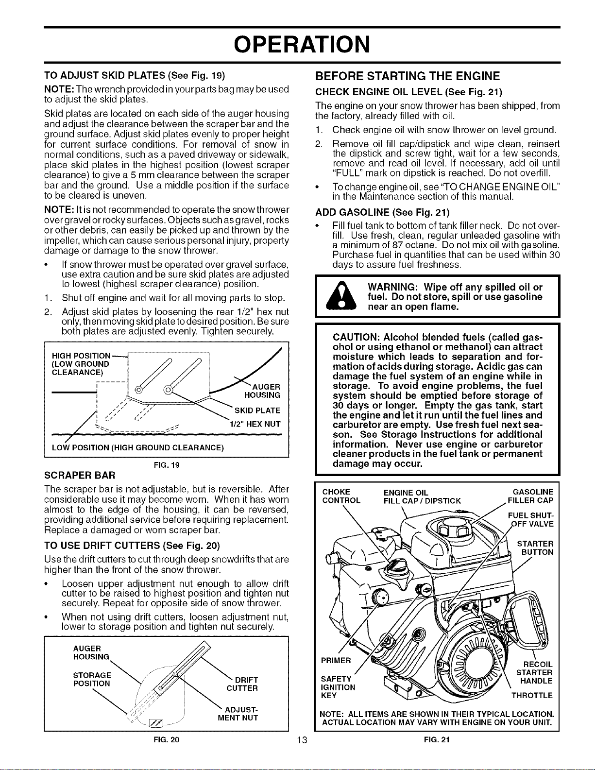
BEFORE STARTING THE ENGINETO ADJUST SKID PLATES (See Fig. 19)
NOTE: The wrench provided in your parts bag may be used
to adjust the skid plates.
Skid plates are located on each side of the auger housing
and adjust the clearance between the scraper bar and the
ground surface. Adjust skid plates evenly to proper height
for current surface conditions. For removal of snow in
normal conditions, such as a paved driveway or sidewalk,
place skid plates in the highest position (lowest scraper
clearance) to give a 5 mm clearance between the scraper
bar and the ground. Use a middle position if the surface
to be cleared is uneven.
NOTE: It is not recommended to operate the snowthrower
over gravel or rocky surfaces. Objects such as gravel, rocks
or other debris, can easily be picked up and thrown by the
impeller, which can cause serious personal injury, property
damage or damage to the snow thrower.
• If snow thrower must be operated over gravel surface,
use extra caution and be sure skid plates are adjusted
to lowest (highest scraper clearance) position.
1. Shut off engine and wait for all moving parts to stop.
2. Adjust skid plates by loosening the rear 1/2" hex nut
only, then moving skid plate todesired position. Be sure
both plates are adjusted evenly. Tighten securely.
HIGH
(LOW GROUND
CLEARANCE)
HOUSING
.///_ _ PLATE
t I
_. ____=====________ 1/2" HEX NUT
/
LOW POSITION (HIGH GROUND CLEARANCE)
FIG. 19
SCRAPER BAR
The scraper bar is not adjustable, but is reversible. After
considerable use it may become worn. When it has worn
almost to the edge of the housing, it can be reversed,
providing additional service before requiring replacement.
Replace a damaged or worn scraper bar.
TO USE DRIFT CUTTERS (See Fig. 20)
Use the drift cutters to cut through deep snowdrifts that are
higher than the front of the snow thrower.
• Loosen upper adjustment nut enough to allow drift
cutter to be raised to highest )osition and tighten nut
securely. Repeat for opposite side of snow thrower.
• When not using drift cutters loosen adjustment nut,
lower to storage position and tighten nut securely.
AUGER
HOUSING
DRIFT
CUTTER
ADJUST-
MENT NUT
CHECK ENGINE OIL LEVEL (See Fig. 21)
The engine on your snow thrower has been shipped, from
the factory, already filled with oil.
1. Check engine oil with snow thrower on level ground.
2. Remove oil fill cap/dipstick and wipe clean, reinsert
the dipstick and screw tight, wait for a few seconds,
remove and read oil level. If necessary, add oil until
"FULL" mark on dipstick is reached. Do not overfill.
• Tochange engine oil, see"TO CHANGE ENGINE OIL"
in the Maintenance section of this manual.
ADD GASOLINE (See Fig. 21)
• Fill fuel tank to bottom of tank filler neck. Do not over-
fill. Use fresh, clean, regular unleaded gasoline with
a minimum of 87 octane. Do not mix oil with gasoline.
Purchase fuel in quantities that can be used within 30
days to assure fuel freshness.
WARNING: Wipe off any spilled oil or
fuel. Do not store, spill or use gasoline
near an open flame.
CAUTION: Alcohol blended fuels (called gas-
ohol or using ethanol or methanol) can attract
moisture which leads to separation and for-
mation of acids during storage. Acidic gas can
damage the fuel system of an engine while in
storage. To avoid engine problems, the fuel
system should be emptied before storage of
30 days or longer. Empty the gas tank, start
the engine and let it run until the fuel lines and
carburetor are empty. Use fresh fuel next sea-
son. See Storage Instructions for additional
information. Never use engine or carburetor
cleaner products in the fuel tank or permanent
damage may occur.
CHOKE ENGINE OIL GASOLINE
CONTROL FILL CAP/DIPSTICK FILLER CAP
FUEL SHUT-
DFFVALVE
STARTER
BUTTON
PRIMER
SAFETY
IGNITION
KEY
RECOIL
STARTER
HANDLE
THROTTLE
NOTE: ALL ITEMS ARE SHOWN IN THEIR TYPICAL LOCATION.
ACTUAL LOCATION MAY VARY WITH ENGINE ON YOUR UNIT.
FIG. 20 13 FIG. 21
OPERATION
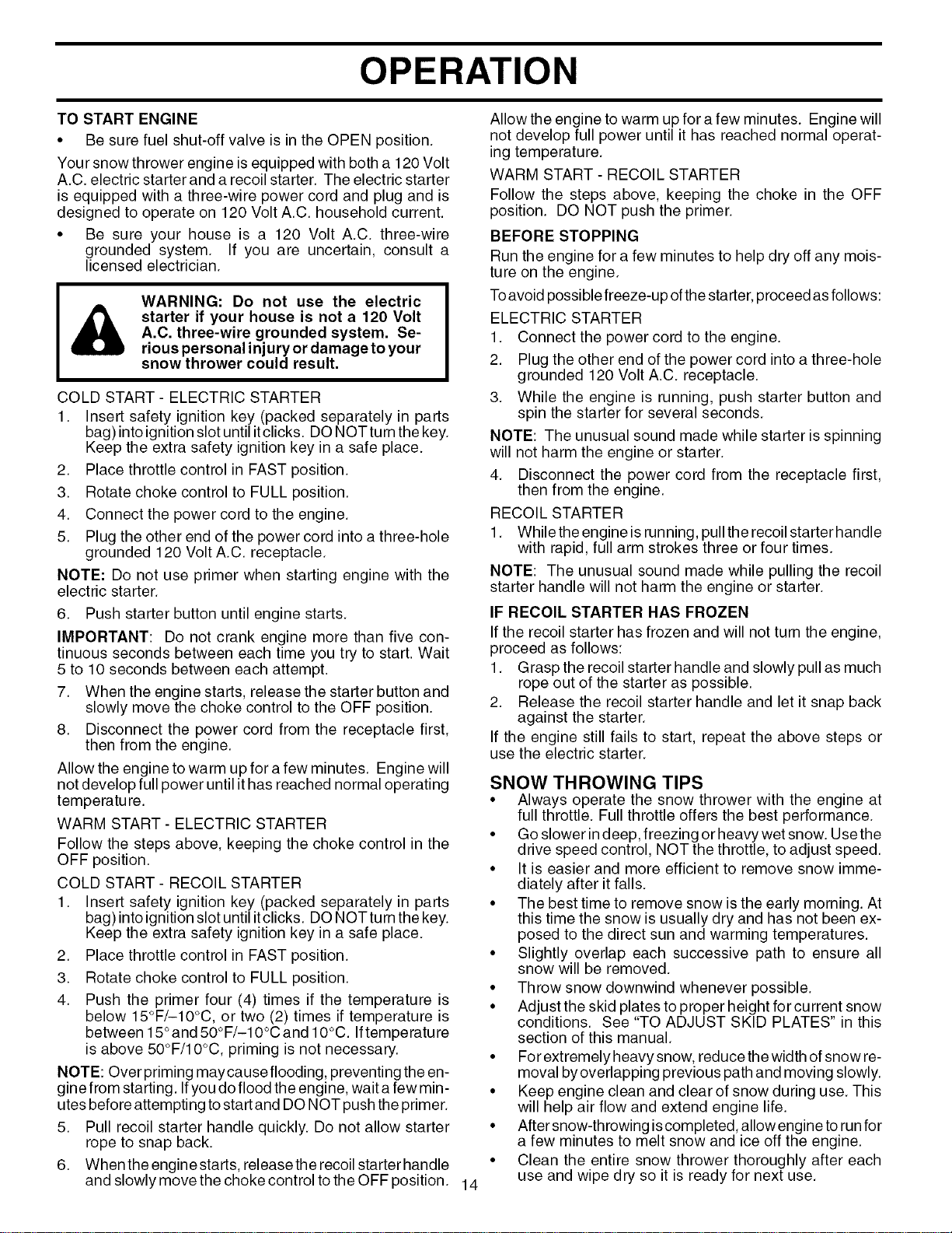
TO START ENGINE
• Be sure fuel shut-off valve is in the OPEN position.
Your snow thrower engine is equipped with both a 120 Volt
A.C. electric starter and a recoil starter. The electric starter
is equipped with a three-wire power cord and plug and is
designed to operate on 120 Volt A.C. household current.
• Be sure your house is a 120 Volt A.C. three-wire
grounded system. If you are uncertain, consult a
licensed electrician.
WARNING: Do not use the electric
starter if your house is not a 120 Volt
A.C. three-wire grounded system. Se-
rious personal injury or damage to your
snow thrower could result.
COLD START- ELECTRIC STARTER
1. Insert safety ignition key (packed separately in parts
bag) into ignition slot until itclicks. DO NOTturn the key.
Keep the extra safety ignition key in a safe place.
2. Place throttle control in FAST position.
3. Rotate choke control to FULL position.
4. Connect the power cord to the engine.
5. Plug the other end of the power cord into a three-hole
grounded 120 Volt A.C. receptacle.
NOTE: Do not use primer when starting engine with the
electric starter.
6. Push starter button until engine starts.
IMPORTANT: Do not crank engine more than five con-
tinuous seconds between each time you try to start. Wait
5 to 10 seconds between each attempt.
7. When the engine starts, release the starter button and
slowly move the choke control to the OFF position.
8. Disconnect the power cord from the receptacle first,
then from the engine.
Allow the engine to warm up for a few minutes. Engine will
not develop full power until it has reached normal operating
temperatu re.
WARM START - ELECTRIC STARTER
Follow the steps above, keeping the choke control in the
OFF position.
COLD START - RECOIL STARTER
1. Insert safety ignition key (packed separately in parts
bag) into ignition slot until itclicks. DO NOTturn the key.
Keep the extra safety ignition key in a safe place.
2. Place throttle control in FAST position.
3. Rotate choke control to FULL position.
4. Push the primer four (4) times if the temperature is
below 15°F/-10°C, or two (2) times if temperature is
between 15°and 50°F/-10°C and 10°C. Iftemperatu re
is above 50°F/10°C, priming is not necessary.
NOTE: Over priming maycause flooding, preventing the en-
gine from starting. Ifyou do flood the engine, wait afew min-
utes before attempting to start and DO NOT push the primer.
5. Pull recoil starter handle quickly. Do not allow starter
rope to snap back.
6. When the engine starts, release the recoil starter handle
and slowly move the choke control to the OFF position. 14
Allow the engine to warm up for a few minutes. Engine will
not develop full power until it has reached normal operat-
ing temperature.
WARM START - RECOIL STARTER
Follow the steps above, keeping the choke in the OFF
position. DO NOT push the primer.
BEFORE STOPPING
Run the engine for a few minutes to help dry off any mois-
ture on the engine.
Toavoid possible freeze-up ofthe starter, proceed as follows:
ELECTRIC STARTER
1. Connect the power cord to the engine.
2. Plug the other end of the power cord into a three-hole
grounded 120 Volt A.C. receptacle.
3. While the engine is running, push starter button and
spin the starter for several seconds.
NOTE: The unusual sound made while starter is spinning
will not harm the engine or starter.
4. Disconnect the power cord from the receptacle first,
then from the engine.
RECOIL STARTER
1. While the engine is running, pull the recoil starterhandle
with rapid, full arm strokes three or four times.
NOTE: The unusual sound made while pulling the recoil
starter handle will not harm the engine or starter.
IF RECOIL STARTER HAS FROZEN
If the recoil starter has frozen and will not turn the engine,
proceed as follows:
1. Grasp the recoil starter handle and slowly pull as much
rope out of the starter as possible.
2. Release the recoil starter handle and let it snap back
against the starter.
If the engine still fails to start, repeat the above steps or
use the electric starter.
SNOW THROWING TIPS
• Always operate the snow thrower with the engine at
full throttle. Full throttle offers the best performance.
• Go slower in deep, freezing or heavy wet snow. Usethe
drive speed control, NOT the throttle, to adjust speed.
• It is easier and more efficient to remove snow imme-
diately after it falls.
• The best time to remove snow is the early morning. At
this time the snow is usually dry and has not been ex-
posed to the direct sun and warming temperatures.
• Slightly overlap each successive path to ensure all
snow will be removed.
• Throw snow downwind whenever possible.
• Adjust the skid plates to proper height for current snow
conditions. See "TO ADJUST SKID PLATES" in this
section of this manual.
• For extremely heavy snow, reduce the width of snow re-
moval byoverlapping previous path and moving slowly.
• Keep engine clean and clear of snow during use. This
will help air flow and extend engine life.
• After snow-throwing iscompleted, allow engine to run for
a few minutes to melt snow and ice off the engine.
• Clean the entire snow thrower thoroughly after each
use and wipe dry so it is ready for next use.
I _ WARNING: Do not operate snow thrower if weather conditions impair visibility. Throwing snow I
I
during a heavy, windy snowstorm can blind you and be hazardous to the safe operation of the
I
snow thrower.
MAINTENANCE
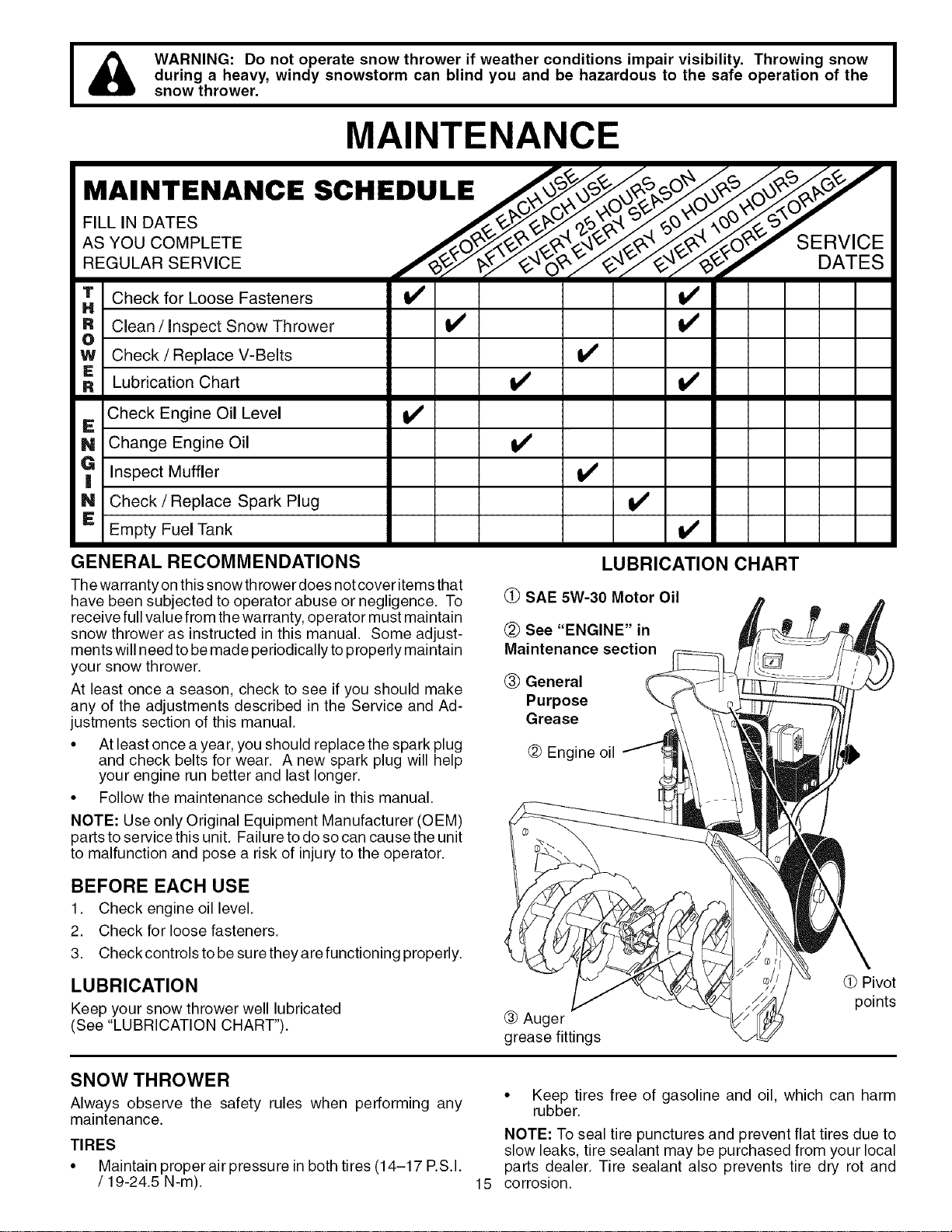
MAINTENANCE SCHEDULE
o TES ......
AS YOU COMPLETE SERVICE
REGULAR SERVICE f_y_C,._._#v DATES
Check for Loose Fasteners V' V'
R Clean / inspect Snow Thrower 1_ if
O
W Check/Replace V=Beks V'
Lubrication Chart V _ I_
Check Engine Oil Level
IE
N Change Engine Oil
Inspect Muffler
N Check / Replace Spark Plug
E
Empty Fuel Tank
v'
v'
v'
v'
v'
GENERAL RECOMMENDATIONS
The warranty on this snowth rower does not cover items that
have been subjected to operator abuse or negligence. To
receive full value from the warranty, operator must maintain
snow thrower as instructed in this manual. Some adjust-
ments will need to be made periodically to properly maintain
your snow thrower.
At least once a season, check to see if you should make
any of the adjustments described in the Service and Ad-
justments section of this manual.
• At least once a year, you should replace the spark plug
and check belts for wear. A new spark plug will help
your engine run better and last longer.
• Follow the maintenance schedule in this manual.
NOTE: Use only Original Equipment Manufacturer (OEM)
parts to service this unit. Failure to do so can cause the unit
to malfunction and pose a risk of injury to the operator.
LUBRICATION CHART
O SAE 5W-30 Motor Oil
@ See "ENGINE" in
Maintenance section
(_ General
Purpose
Grease
@ Engine oil
BEFORE EACH USE
1. Check engine oil level.
2. Check for loose fasteners.
3. Check controls to be sure they are functioning properly.
LUBRICATION
Keep your snow thrower well lubricated
(See "LUBRICATION CHART").
® Auger
grease fittings
Pivot
points
SNOW THROWER
Always observe the safety rules when performing any
maintenance.
TIRES
• Maintain proper air pressure in both tires (14-17 P.S.I.
/ 19-24.5 N-m). 15
• Keep tires free of gasoline and oil, which can harm
rubber.
NOTE: To seal tire punctures and prevent flat tires due to
slow leaks, tire sealant may be purchased from your local
parts dealer. Tire sealant also prevents tire dry rot and
corrosion.
MAINTENANCE
V-BELTS TO CHANGE ENGINE OIL
Check V-belts for deterioration and wear after every 50
hours of operation and replace if necessary. The belts
are not adjustable. Replace belts if they begin to slip from
wear. (See "TO REMOVE BELT COVER" in the Service
and Adjustments section of this manual).
The V-belts on your snow thrower are of special construction
and should be replaced byoriginal equipment manufacturer
(OEM) belts available from your nearest dealer. Using other
than OEM belts can cause personal injury or damage to
the snow thrower.
AUGER GEAR CASE
• The gear case was filled with lubricant to the proper
level at the factory. The only time the lubricant needs
attention is if service has been performed on the gear
case.
• If lubricant is required, use only Ronex ED #1 grease.
TRACTION DRIVE SYSTEM
DO NOT lubricate the drive components inside the snow
thrower. The sprockets, hex shafts, drive disc and friction
wheel require no lubrication. The bearings and bushings
are lifetime lubricated and require no maintenance.
CAUTION: Any lubricating of the above compo-
nents can cause contamination of the friction
wheel and damage to the drive system of your
snow thrower.
ENGINE
LUBRICATION
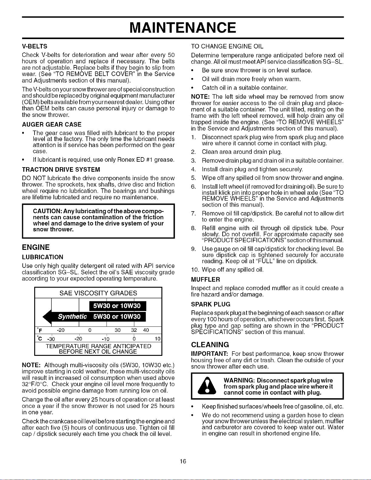
Use only high quality detergent oil rated with API service
classification SG-SL. Select the oil's SAE viscosity grade
according to your expected operating temperature.
SAE VISCOSITY GRADES
IE I
I] [,_1i][&_
4 I
°F -20 0 30 32 40
°c -3o -2b 40 6 10
TEMPERATURE RANGE ANTICIPATED
BEFORE NEXT OIL CHANGE
NOTE: Although multi-viscosity oils (5W30, 10W30 etc.)
improve starting in cold weather, these multi-viscosity oils
will result in increased oil consumption when used above
32°F/0°C. Check your engine oil level more frequently to
avoid possible engine damage from running low on oil.
Change the oil after every 25 hours of operation or at least
once a year if the snow thrower is not used for 25 hours
in one year.
Check the crankcase oil level before starting the engine and
after each five (5) hours of continuous use. Tighten oil fill
cap / dipstick securely each time you check the oil level.
Determine temperature range anticipated before next oil
change. All oil must meet API service classification SG-SL.
• Be sure snow thrower is on level surface.
• Oil will drain more freely when warm.
• Catch oil in a suitable container.
NOTE: The left side wheel may be removed from snow
thrower for easier access to the oil drain plug and place-
ment of a suitable container. The unit tilted, resting on the
frame with the left wheel removed, will help drain any oil
trapped inside the engine. (See "TO REMOVE WHEELS"
in the Service and Adjustments section of this manual).
1. Disconnect spark plug wire from spark plug and place
wire where it cannot come in contact with plug.
2. Clean area around drain plug.
3. Remove drain plug and drain oil in asuitable container.
4. Install drain plug and tighten securely.
5. Wipe off any spilled oil from snow thrower and engine.
6. Install left wheel (if removed fordraining oil). Be sure to
install klick pin into proper hole in wheel axle (See "TO
REMOVE WHEELS" in the Service and Adjustments
section of this manual).
7. Remove oil fill cap/dipstick. Be careful not to allow dirt
to enter the engine.
8. Refill engine with oil through oil dipstick tube. Pour
slowly. Do not overfill. For approximate capacity see
"PRODUCT SPECIFICATIONS" section ofthis manual.
9. Use gauge on oil fill cap/dipstick for checking level. Be
sure dipstick cap is tightened securely for accurate
reading. Keep oil at "FULL" line on dipstick.
10. Wipe off any spilled oil.
MUFFLER
Inspect and replace corroded muffler as it could create a
fire hazard and/or damage.
SPARK PLUG
Replace spark plug atthe beginning of each season or after
every 1O0hours of operation, whichever occurs first. Spark
plug type and gap setting are shown in the "PRODUCT
SPECIFICATIONS" section of this manual.
CLEANING
IMPORTANT: For best performance, keep snow thrower
housing free of any dirt or trash. Clean the outside of your
snow thrower after each use.
J & WARNING: Disconnectsparkplugwire J
from spark plug and place wire where it
cannot come in contact with plug.
Keep finished surfaces/wheels free of gasoline, oil, etc.
We do not recommend using a garden hose to clean
your snow thrower unless the electrical system, muffler
and carburetor are covered to keep water out. Water
in engine can result in shortened engine life.
16
SERVICE AND ADJUSTMENTS
WARNING: To avoid serious injury, before
performing any service or adjustments:
1. Be sure throttle is in STOP position.
2. Remove safety ignition key.
3. Make sure the augers and all moving
parts have completely stopped.
4. Disconnect spark plug wire from
spark plug and place wire where it
cannot come in contact with plug.
SNOW THROWER
TO ADJUST SNOW THROWER HEIGHT
See "TO ADJUST SKID PLATES" and "SCRAPER BAR"
in the Operation section of this manual.
CHUTE DEFLECTOR
The chute deflector, attached to the top of the discharge
chute, is provided to direct discharging snow away from
the operator. If the deflector becomes damaged, it should
be replaced.
I & WARNING: To avoid serious injury, I
never operate your snow thrower with
the deflector removed or damaged.
• Tochange direction and/or distance snowis discharged,
see "TO CONTROL SNOW DISCHARGE" in the Op-
eration section of this manual.
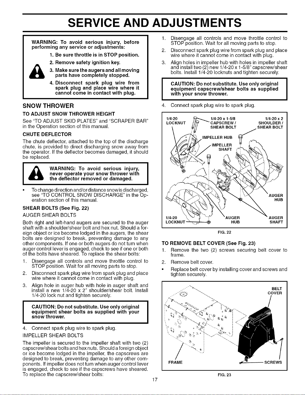
SHEAR BOLTS (See Fig. 22)
AUGER SHEAR BOLTS
Both right and left-hand augers are secured to the auger
shaft with a shoulder/shear bolt and hex nut. Should a for-
eign object or ice become lodged in the augers, the shear
bolts are designed to break, preventing damage to any
other components. If one or both augers do not turn when
auger control lever is engaged, check to see ifone or both
of the bolts have sheared. To replace the shear bolts:
1. Disengage all controls and move throttle control to
STOP position. Wait for all moving parts to stop.
2. Disconnect spark plug wire from spark plug and place
wire where it cannot come in contact with plug.
3. Align hole in auger hub with hole in auger shaft and
install a new 1/4-20 x 2" shoulder/shear bolt. Install
1/4-20 lock nut and tighten securely.
I CAUTION: Do not substitute. Use only original I
I
equipment shear bolts as supplied with your
I
snow thrower.
4. Connect spark plug wire to spark plug.
IMPELLER SHEAR BOLTS
The impeller is secured to the impeller shaft with two (2)
capscrew/shear bolts and hex nuts. Should a foreign object
or ice become lodged in the impeller, the capscrews are
designed to break, preventing damage to any other com-
ponents. If impeller does not turn when auger control lever
is engaged, check to see if the capscrews have sheared.
To replace the capscrew/shear bolts:
1. Disengage all controls and move throttle control to
STOP position. Wait for all moving parts to stop.
2. Disconnect spark plug wire from spark plug and place
wire where it cannot come in contact with plug.
3. Align holes in impeller hub with holes in impeller shaft
and install two (2) new 1/4-20 x 1-5/8" capscrew/shear
bolts. Install 1/4-20 Iocknuts and tighten securely.
I
4.
CAUTION: Do not substitute. Use only original
equipment capscrew/shear bolts as supplied
with your snow thrower.
Connect spark plug wire to spark plug.
I
1/O4-_ONLIT _'_ 1sC/4HA-EP2i_R1BEo5IV_ sSHHEO1'AU4-iBDOcEXRLi
\ opE..E..oo
FIG. 22
TO REMOVE BELT COVER (See Fig. 23)
1. Remove the two (2) screws securing belt cover to
frame.
2. Remove belt cover.
• Replace belt cover by installing cover and screws and
tighten securely.
FIG. 23
17
SERVICE AND ADJUSTMENTS
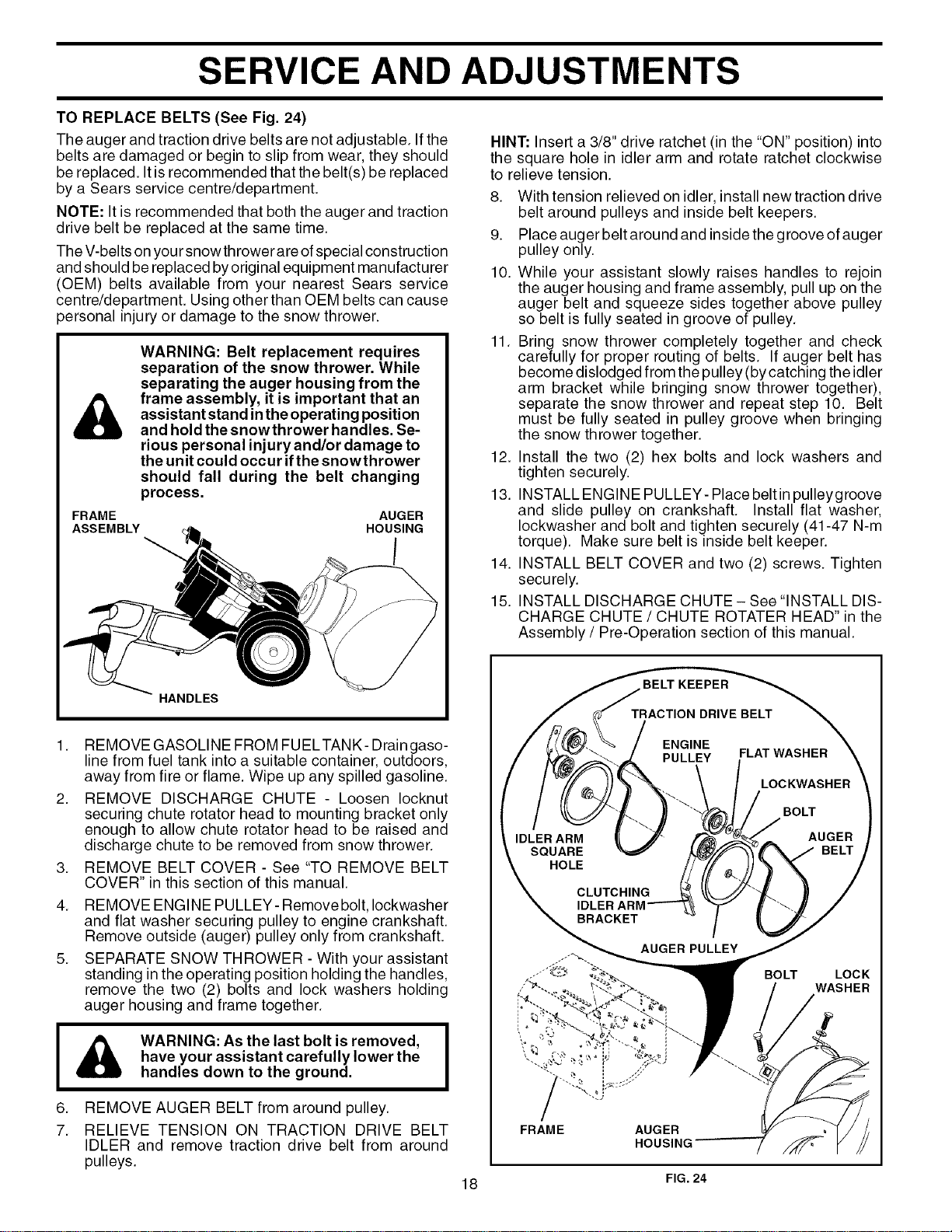
TO REPLACE BELTS (See Fig. 24)
The auger and traction drive belts are not adjustable. Ifthe
belts are damaged or begin to slip from wear, they should
be replaced. It is recommended that the belt(s) be replaced
by a Sears service centre/department.
NOTE: It is recommended that both the auger and traction
drive belt be replaced at the same time.
The V-belts on your snowthrower are of special construction
and should be replaced byoriginal equipment manufacturer
(OEM) belts available from your nearest Sears service
centre/department. Using other than OEM belts can cause
)ersonal injury or damage to the snow thrower.
&
WARNING: Belt replacement requires
separation of the snow thrower. While
separating the auger housing from the
frame assembly, it is important that an
assistant stand inthe operating position
and hold the snowthrower handles. Se-
rious personal injury and/or damage to
the unit could occur ifthe snowthrower
should fall during the belt changing
process.
FRAME AUGER
ASSEMBLY HOUSING
HINT: Insert a 3/8" drive ratchet (in the "ON" position) into
the square hole in idler arm and rotate ratchet clockwise
to relieve tension.
8. With tension relieved on idler, install new traction drive
belt around pulleys and inside belt keepers.
9. Place auger belt around and inside the groove of auger
pulley only.
10. While your assistant slowly raises handles to rejoin
the auger housing and frame assembly, pull up on the
auger belt and squeeze sides together above pulley
so belt is fully seated in groove of pulley.
11. Bring snow thrower completely together and check
carefully for proper routing of belts. If auger belt has
become dislodged from the pulley (by catching the idler
arm bracket while bringing snow thrower together),
separate the snow thrower and repeat step 10. Belt
must be fully seated in pulley groove when bringing
the snow thrower together.
12. Install the two (2) hex bolts and lock washers and
tighten securely.
13. INSTALL ENGINE PULLEY- Place belt in pulleygroove
and slide pulley on crankshaft. Install flat washer,
Iockwasher and bolt and tighten securely (41-47 N-m
torque). Make sure belt is inside belt keeper.
14. INSTALL BELT COVER and two (2) screws. Tighten
securely.
15. INSTALL DISCHARGE CHUTE - See "INSTALL DIS-
CHARGE CHUTE / CHUTE ROTATER HEAD" in the
Assembly / Pre-Operation section of this manual.
1. REMOVE GASOLINE FROM FUELTANK-Draingaso-
line from fuel tank into a suitable container, outdoors,
away from fire or flame. Wipe up any spilled gasoline.
2. REMOVE DISCHARGE CHUTE - Loosen Iocknut
securing chute rotator head to mounting bracket only
enough to allow chute rotator head to be raised and
discharge chute to be removed from snow thrower.
3. REMOVE BELT COVER - See "TO REMOVE BELT
COVER" in this section of this manual.
4. REMOVE ENGINE PULLEY- Remove bolt, Iockwasher
and flat washer securing pulley to engine crankshaft.
Remove outside (auger) pulley only from crankshaft.
5. SEPARATE SNOW THROWER - With your assistant
standing in the operating position holding the handles,
remove the two (2) bolts and lock washers holding
auger housing and frame together.
I & WARNING: As the last bolt is removed, I
have your assistant carefully lower the
handles down to the ground.
6.
7.
REMOVE AUGER BELT from around pulley.
RELIEVE TENSION ON TRACTION DRIVE BELT
IDLER and remove traction drive belt from around
pulleys.
HOLE
FRAME AUGER
HOUSING
BELT
LOC K
WASHER
18 FIG. 24
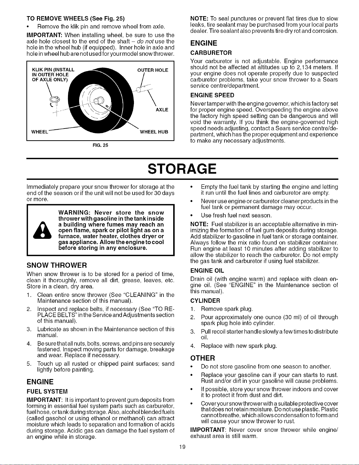
TO REMOVE WHEELS (See Fig. 25)
• Remove the klik pin and remove wheel from axle.
IMPORTANT: When installing wheel, be sure to use the
axle hole closest to the end of the shaft - do not use the
hole in the wheel hub (if equipped). Inner hole in axle and
hole inwheel hub are not used for your model snowthrower.
KLIK PIN (INSTALL
IN OUTER HOLE
OF AXLE ONLY)
OUTER HOLE
AXLE
WHEEL WHEEL HUB
NOTE: To seal punctures or prevent flat tires due to slow
leaks, tire sealant may be purchased from your local parts
dealer. Tire sealant also prevents tire dry rot and corrosion.
ENGINE
CARBURETOR
Your carburetor is not adjustable. Engine performance
should not be affected at altitudes up to 2,134 meters. If
your engine does not operate properly due to suspected
carburetor problems, take your snow thrower to a Sears
service centre/department.
ENGINE SPEED
FIG. 25
STORAGE
Never tamper with the engine governor, which isfactory set
for proper engine speed. Overspeeding the engine above
the factory high speed setting can be dangerous and will
void the warranty. If you think the engine-governed high
speed needs adjusting, contact a Sears service centre/de-
partment, which has the proper equipment and experience
to make any necessary adjustments.
Immediately prepare your snow thrower for storage at the
end of the season or if the unit will not be used for 30 days
or more.
&
WARNING: Never store the snow
thrower with gasoline in the tank inside
a building where fumes may reach an
open flame, spark or pilot light as on a
furnace, water heater, clothes dryer or
gas appliance. Allow the engine to cool
before storing in any enclosure.
SNOW THROWER
3.
4.
When snow thrower is to be stored for a period of time,
clean it thoroughly, remove all dirt, grease, leaves, etc.
Store in a clean, dry area.
1. Clean entire snow thrower (See "CLEANING" in the
Maintenance section of this manual).
2. Inspect and replace belts, if necessary (See "TO RE-
PLACE BELTS" in the Service and Adjustments section
of this manual).
Lubricate as shown in the Maintenance section of this
manual.
5.
Be sure that all nuts, bolts, screws, and pins are securely
fastened. Inspect moving parts for damage, breakage
and wear. Replace if necessary.
Touch up all rusted or chipped paint surfaces; sand
lightly before painting.
ENGINE
FUEL SYSTEM
IMPORTANT: It is important to prevent gum deposits from
forming in essential fuel system parts such as carburetor,
fuel hose, or tank during storage. Also, alcohol blended fuels
(called gasohol or using ethanol or methanol) can attract
moisture which leads to separation and formation of acids
during storage. Acidic gas can damage the fuel system of
an engine while in storage.
• Empty the fuel tank by starting the engine and letting
it run until the fuel lines and carburetor are empty.
• Never use engine or carburetor cleaner products in the
fuel tank or permanent damage may occur.
• Use fresh fuel next season.
NOTE: Fuel stabilizer is an acceptable alternative in min-
imizing the formation of fuel gum deposits during storage.
Add stabilizer to gasoline in fuel tank or storage container.
Always follow the mix ratio found on stabilizer container.
Run engine at least 10 minutes after adding stabilizer to
allow the stabilizer to reach the carburetor. Do not empty
the gas tank and carburetor if using fuel stabilizer.
ENGINE OIL
Drain oil (with engine warm) and replace with clean en-
gine oil. (See "ENGINE" in the Maintenance section of
this manual).
CYLINDER
1. Remove spark plug.
2. Pour approximately one ounce (30 ml) of oil through
spark plug hole into cylinder.
3. Pull recoil starter handle slowlya fewtimes todistribute
oil.
4. Replace with new spark plug.
OTHER
• Do not store gasoline from one season to another.
• Replace your gasoline can if your can starts to rust.
Rust and/or dirt in your gasoline will cause problems.
• If possible, store your snow thrower indoors and cover
it to protect it from dust and dirt.
• Cover your snow throwerwith a suitable protective cover
that does not retain moisture. Do not use plastic. Plastic
cannot breathe, which allows condensation to form and
will cause your snow thrower to rust.
IMPORTANT: Never cover snow thrower while engine/
exhaust area is still warm.
19
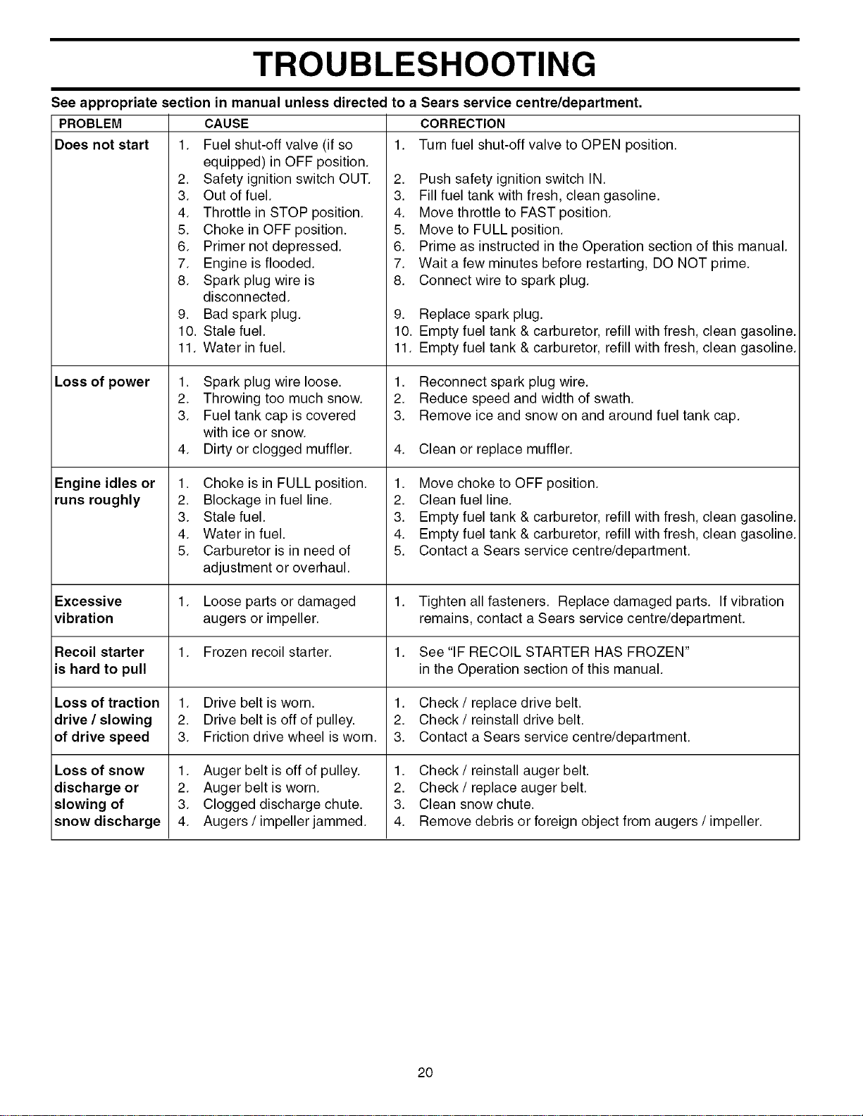
TROUBLESHOOTING
See appropriate section in manual unless directed to a Sears service centre/department.
PROBLEM CORRECTION
Does not start 1. 1. Turn fuel shut-off valve to OPEN position.
Loss of power
Engine idles or
runs roughly
Excessive
vibration
Recoil starter
is hard to pull
Loss of traction
drive / slowing
of drive speed
Loss of snow
discharge or
slowing of
snow discharge
CAUSE
Fuel shut-off valve (if so
equipped) in OFF position.
2. Safety ignition switch OUT.
3. Out of fuel.
4. Throttle in STOP position.
5. Choke in OFF position.
6. Primer not depressed.
7. Engine is flooded.
8. Spark plug wire is
disconnected.
9. Bad spark plug.
10. Stale fuel.
11. Water in fuel.
1. Spark plug wire loose.
2. Throwing too much snow.
3. Fuel tank cap is covered
with ice or snow.
4. Dirty or clogged muffler.
1. Choke is in FULL position.
2. Blockage in fuel line.
3. Stale fuel.
4. Water in fuel.
5. Carburetor is in need of
adjustment or overhaul.
Loose parts or damaged
augers or impeller.
1. Frozen recoil starter.
1. Drive belt is worn.
2. Drive belt is off of pulley.
3. Friction drive wheel is worn.
1. Auger belt is off of pulley.
2. Auger belt is worn.
3. Clogged discharge chute.
4. Augers/impeller jammed.
2. Push safety ignition switch IN.
3. Fill fuel tank with fresh, clean gasoline.
4. Move throttle to FAST position.
5. Move to FULL position.
6. Prime as instructed in the Operation section of this manual.
7. Wait a few minutes before restarting, DO NOT prime.
8. Connect wire to spark plug.
9. Replace spark plug.
10. Empty fuel tank & carburetor, refill with fresh, clean gasoline.
11. Empty fuel tank & carburetor, refill with fresh, clean gasoline.
1. Reconnect spark plug wire.
2. Reduce speed and width of swath.
3. Remove ice and snow on and around fuel tank cap.
4. Clean or replace muffler.
1. Move choke to OFF position.
2. Clean fuel line.
3. Empty fuel tank & carburetor, refill with fresh, clean gasoline.
4. Empty fuel tank & carburetor, refill with fresh, clean gasoline.
5. Contact a Sears service centre/department.
1. Tighten all fasteners. Replace damaged parts. If vibration
remains, contact a Sears service centre/department.
1. See "IF RECOIL STARTER HAS FROZEN"
in the Operation section of this manual.
1. Check / replace drive belt.
2. Check / reinstall drive belt.
3. Contact a Sears service centre/department.
1. Check / reinstall auger belt.
2. Check / replace auger belt.
3. Clean snow chute.
4. Remove debris or foreign object from augers / impeller.
20

SERVICE NOTES
21
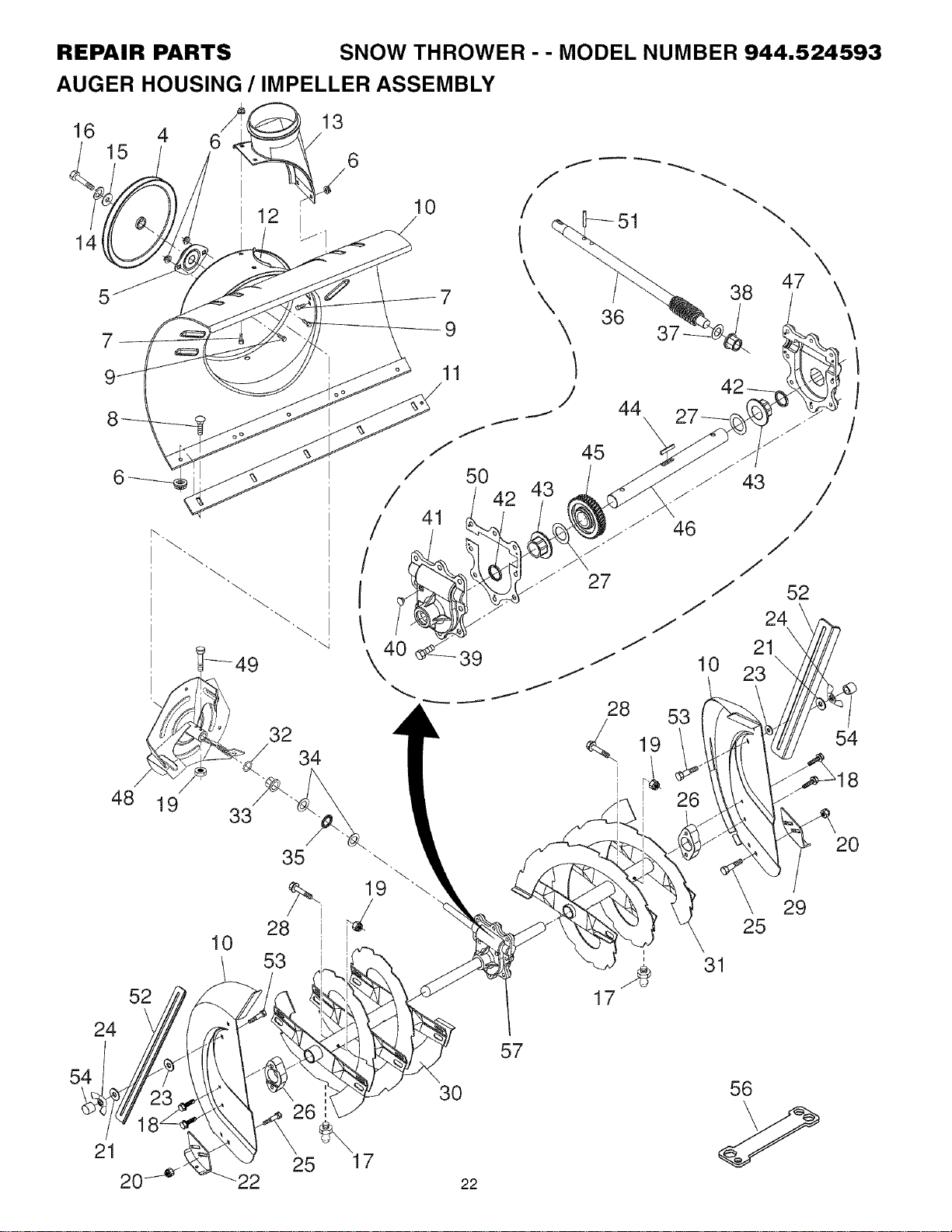
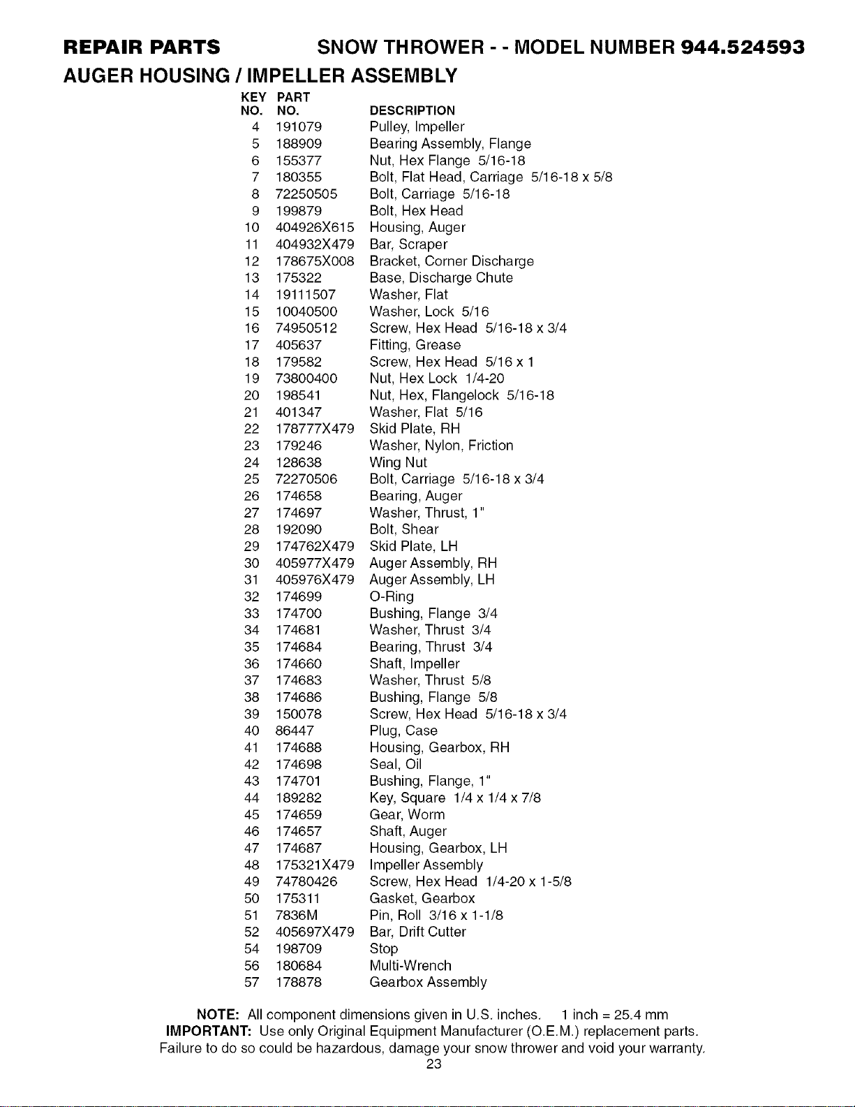
REPAIR PARTS SNOW THROWER -- MODEL NUMBER 944.524593
AUGER HOUSING / IMPELLER ASSEMBLY
16
15
10
14
7
7
9
11
32
34
\
36
37-
44
\
47
38 /
10
28 53
, 19
\
/
/
/
J
52
24
21
23
\
\
/
/
/
54
48 19
52
24
54
21
2(:
33
10
35
28
53
26
25
19 \
17
30
22
57
i
i
17
26
25
31
29
20
56
REPAIR PARTS SNOW THROWER - - MODEL NUMBER 944.524593
AUGER HOUSING / IMPELLER ASSEMBLY
KEY PART
NO. NO.
4 191079
5 188909
6 155377
7 180355
8 72250505
9 199879
10 404926X615
11 404932X479
12 178675X008
13 175322
14 19111507
15 10040500
16 74950512
17 405637
18 179582
19 73800400
20 198541
21 401347
22 178777X479
23 179246
24 128638
25 72270506
26 174658
27 174697
28 192090
29 174762X479
30 405977X479
31 405976X479
32 174699
33 174700
34 174681
35 174684
36 174660
37 174683
38 174686
39 150078
40 86447
41 174688
42 174698
43 174701
44 189282
45 174659
46 174657
47 174687
48 175321X479
49 74780426
50 175311
51 7836M
52 405697X479
54 198709
56 180684
57 178878
DESCRIPTION
Pulley, Impeller
Bearing Assembly, Flange
Nut, Hex Flange 5/16-18
Bolt, Flat Head, Carriage 5/16-18 x 5/8
Bolt, Carriage 5/16-18
Bolt, Hex Head
Housing, Auger
Bar, Scraper
Bracket, Corner Discharge
Base, Discharge Chute
Washer, Flat
Washer, Lock 5/16
Screw, Hex Head 5/16-18 x 3/4
Fitting, Grease
Screw, Hex Head 5/16 x 1
Nut, Hex Lock 1/4-20
Nut, Hex, Flangelock 5/16-18
Washer, Flat 5/16
Skid Plate, RH
Washer, Nylon, Friction
Wing Nut
Bolt, Carriage 5/16-18 x 3/4
Bearing, Auger
Washer, Thrust, 1"
Bolt, Shear
Skid Plate, LH
Auger Assembly, RH
Auger Assembly, LH
O-Ring
Bushing, Flange 3/4
Washer, Thrust 3/4
Bearing, Thrust 3/4
Shaft, Impeller
Washer, Thrust 5/8
Bushing, Flange 5/8
Screw, Hex Head 5/16-18 x 3/4
Plug, Case
Housing, Gearbox, RH
Seal, Oil
Bushing, Flange, 1"
Key, Square 1/4 x 1/4 x 7/8
Gear, Worm
Shaft, Auger
Housing, Gearbox, LH
Impeller Assembly
Screw, Hex Head 1/4-20 x 1-5/8
Gasket, Gearbox
Pin, Roll 3/16 x 1-1/8
Bar, Drift Cutter
Stop
Multi-Wrench
Gearbox Assembly
NOTE: All component dimensions given in U.S. inches. 1 inch = 25.4 mm
IMPORTANT: Use only Original Equipment Manufacturer (O.E.M.) replacement parts.
Failure to do so could be harardous, damage your snow thrower and void your warranty.
23
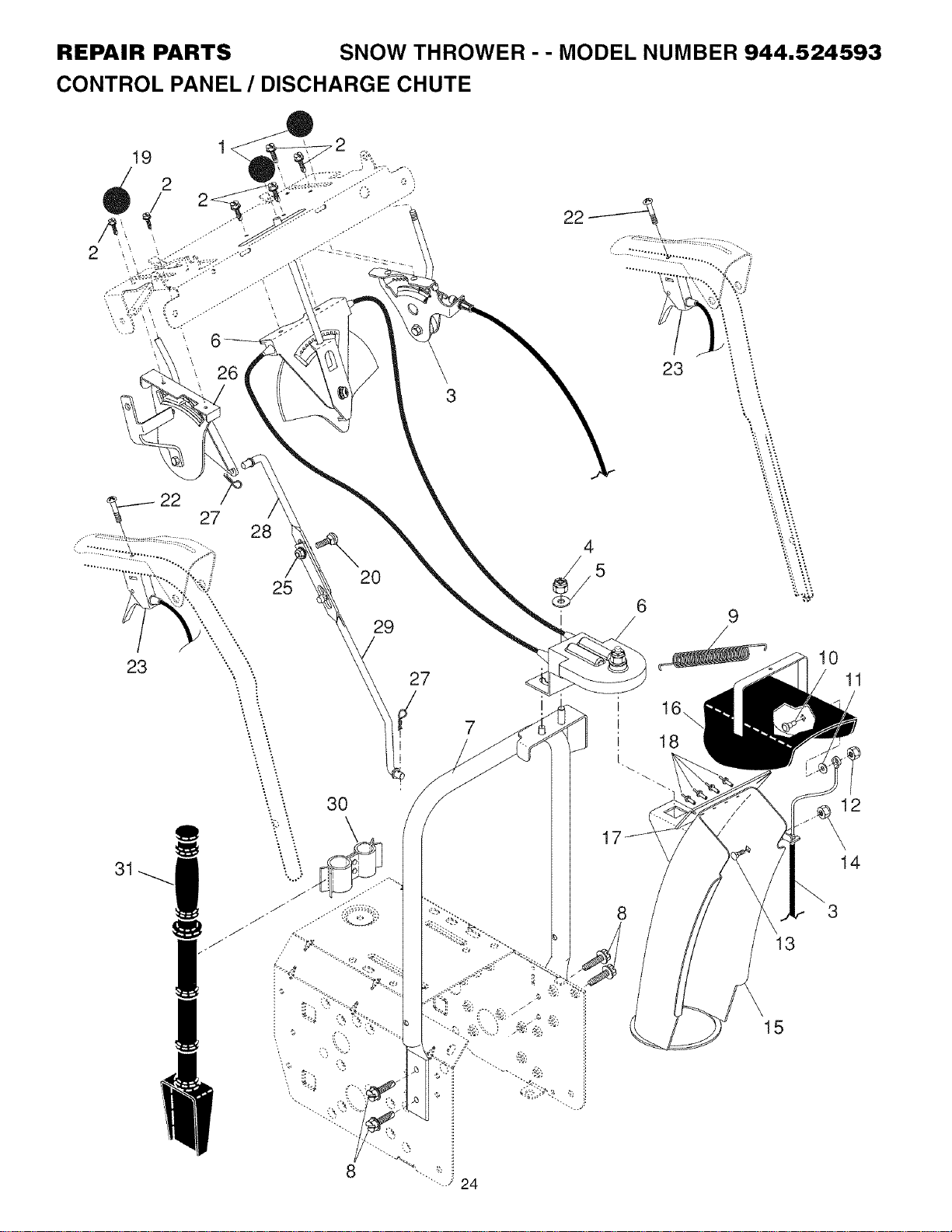
REPAIR PARTS SNOW THROWER -- MODEL NUMBER 944.524593
CONTROL PANEL / DISCHARGE CHUTE
26
22 27
23
31
28
20
25
29
8
3
27
23
6
/
7
16\
18
24
-..-
13
15
10
11
12
14
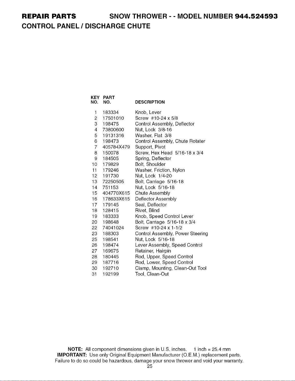
REPAIR PARTS SNOW THROWER - - MODEL NUMBER 944.524593
CONTROL PANEL / DISCHARGE CHUTE
KEY PART
NO. NO. DESCRIPTION
1 183334
2 17501010
3 198475
4 73800600
5 19131316
6 198473
7 405784X479
8 150078
9 184505
10 179829
11 179246
12 191730
13 72250505
14 751153
15 404770X615
16 178633X615
17 179145
18 128415
19 183333
20 198648
22 74041024
23 188303
25 198541
26 198474
27 169675
28 180445
29 187716
30 192710
31 192199
Knob, Lever
Screw #10-24 x 5/8
Control Assembly, Deflector
Nut, Lock 3/8-16
Washer, Flat 3/8
Control Assembly, Chute Rotater
Support, Pivot
Screw, Hex Head 5/16-18 x 3/4
Spring, Deflector
Bolt, Shoulder
Washer, Friction, Nylon
Nut, Lock 1/4-20
Bolt, Carriage 5/16-18
Nut, Lock 5/16-18
Chute Assembly
Deflector Assembly
Seal, Deflector
Rivet, Blind
Knob, Speed Control Lever
Bolt, Carriage 5/16-18 x 3/4
Screw #10-24 x 1-1/2
Control Assembly, Power Steering
Nut, Lock 5/16-18
Lever Assembly, Speed Control
Retainer, Hairpin
Rod, Upper, Speed Control
Rod, Lower, Speed Control
Clamp, Mounting, Clean-Out Tool
Tool, Clean-Out
NOTE: All component dimensions given in U.S. inches. 1 inch = 25.4 mm
IMPORTANT: Use only Original Equipment Manufacturer (O.E.M.) replacement parts.
Failure to do so could be haFardous, damage your snow thrower and void your warranty.
25
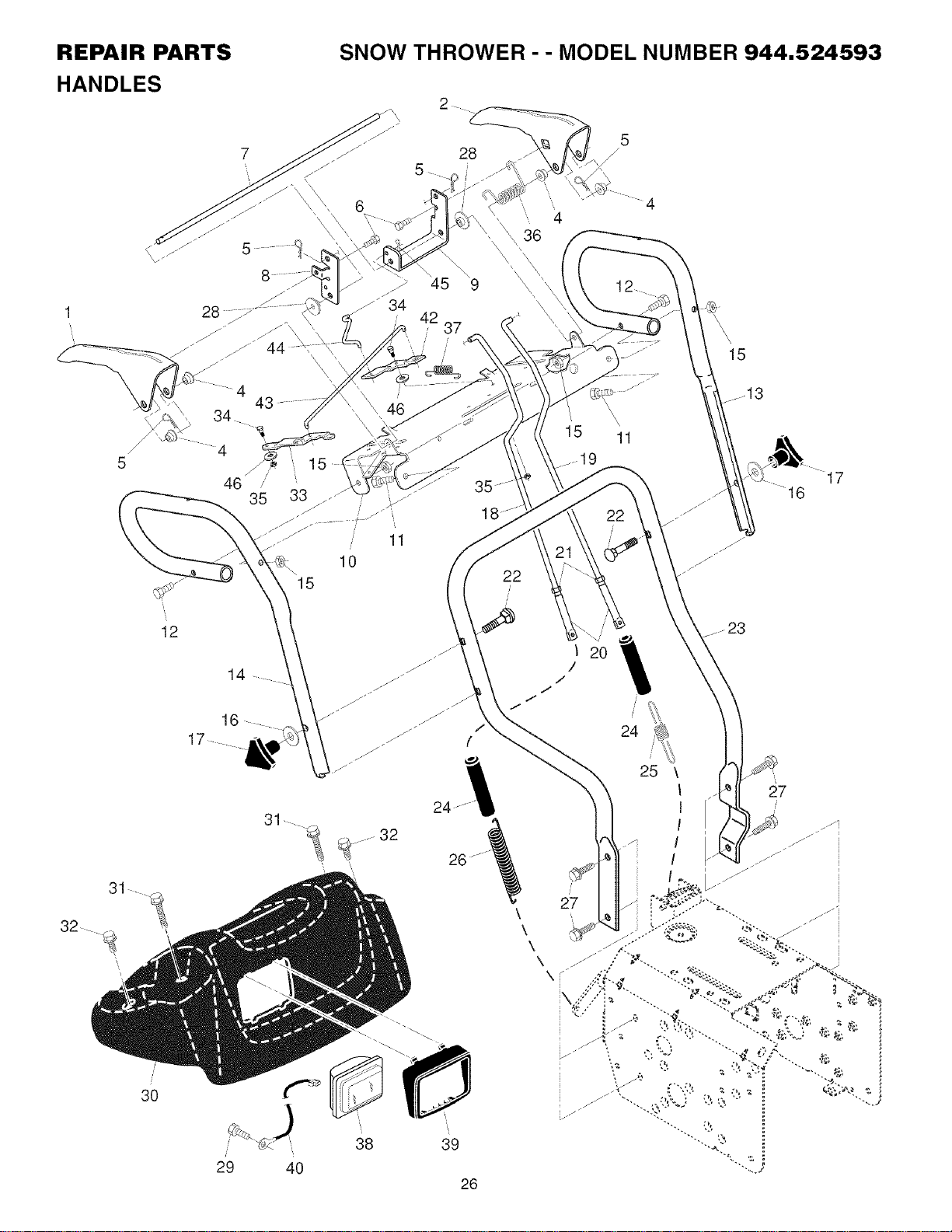
REPAIR PARTS SNOW THROWER -- MODEL NUMBER 944.524593
HANDLES
5
\\\
4
43
34_
4
46
15
28
5
\
45
42
37
22
4
\
15 11
19
12
22
15
.13
17
/'
30
12
14
16
17
9
38 39
29 40
26
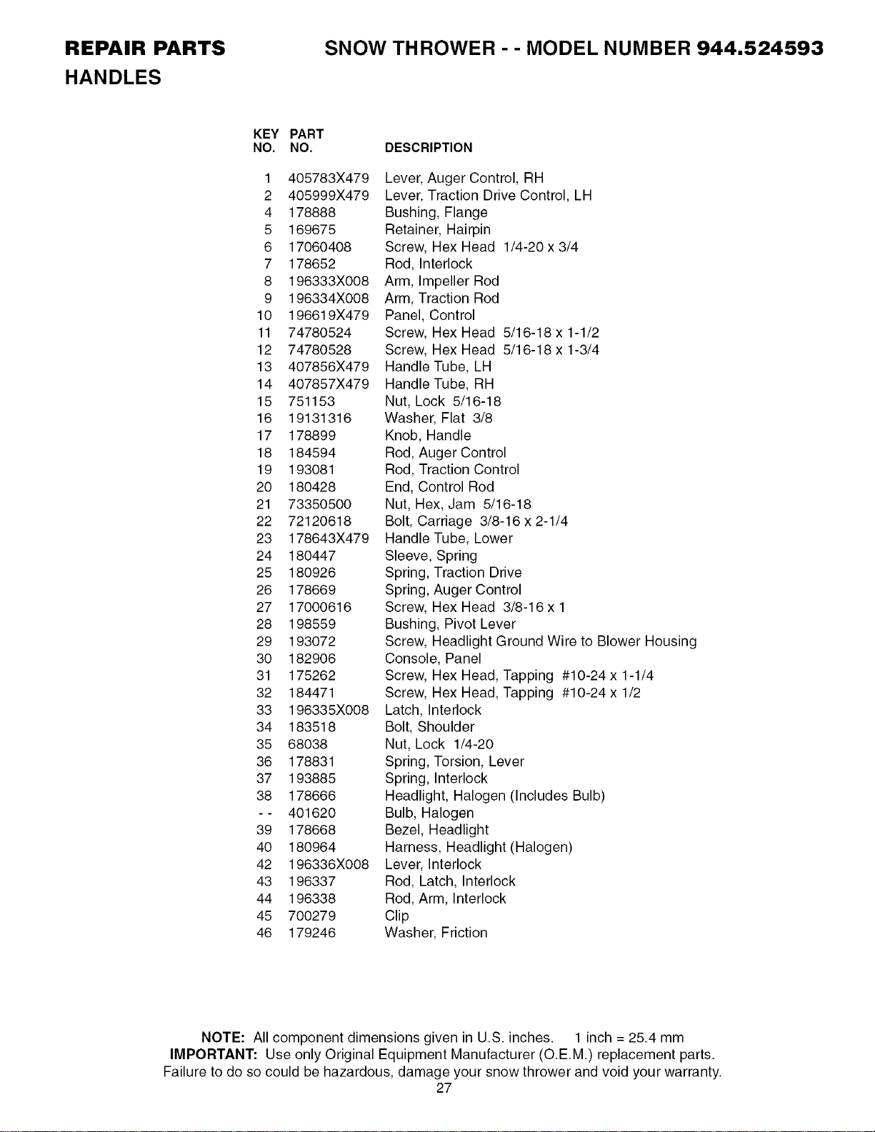
REPAIR PARTS
HANDLES
SNOW THROWER - - MODEL NUMBER 944.524593
KEY PART
NO. NO.
1 405783X479
2 405999X479
4 178888
5 169675
6 17060408
7 178652
8 196333X008
9 196334X008
10 196619X479
11 74780524
12 74780528
13 407856X479
14 407857X479
15 751153
16 19131316
17 178899
18 184594
19 193081
20 180428
21 73350500
22 72120618
23 178643X479
24 180447
25 180926
26 178669
27 17000616
28 198559
29 193072
30 182906
31 175262
32 184471
33 196335X008
34 183518
35 68038
36 178831
37 193885
38 178666
-- 401620
39 178668
40 180964
42 196336X008
43 196337
44 196338
45 700279
46 179246
DESCRIPTION
Lever, Auger Control, RH
Lever, Traction Drive Control, LH
Bushing, Flange
Retainer, Hairpin
Screw, Hex Head 1/4-20 x 3/4
Rod, Interlock
Arm, Impeller Rod
Arm, Traction Rod
Panel, Control
Screw, Hex Head 5/16-18 x 1-1/2
Screw, Hex Head 5/16-18 x 1-3/4
Handle Tube, LH
Handle Tube, RH
Nut, Lock 5/16-18
Washer, Flat 3/8
Knob, Handle
Rod, Auger Control
Rod, Traction Control
End, Control Rod
Nut, Hex, Jam 5/16-18
Bolt, Carriage 3/8-16 x 2-1/4
Handle Tube, Lower
Sleeve, Spring
Spring, Traction Drive
Spring, Auger Control
Screw, Hex Head 3/8-16 x 1
Bushing, Pivot Lever
Screw, Headlight Ground Wire to Blower Housing
Console, Panel
Screw, Hex Head, Tapping #10-24 x 1-1/4
Screw, Hex Head, Tapping #10-24 x 1/2
Latch, Interlock
Bolt, Shoulder
Nut, Lock 1/4-20
Spring, Torsion, Lever
Spring, Interlock
Headlight, Halogen (Includes Bulb)
Bulb, Halogen
Bezel, Headlight
Harness, Headlight (Halogen)
Lever, Interlock
Rod, Latch, Interlock
Rod, Arm, Interlock
Clip
Washer, Friction
NOTE: All component dimensions given in U.S. inches. 1 inch = 25.4 mm
IMPORTANT: Use only Original Equipment Manufacturer (O.E.M.) replacement parts.
Failure to do so could be hazardous, damage your snow thrower and void your warranty.
27
REPAIR PARTS SNOW THROWER -- MODEL NUMBER 944.524593
DRIVE
2
1
2
7
,5_-/_ 27
2
19
18
17
18
23
6
5
43
34
26
28
22
39
40
28 35 33
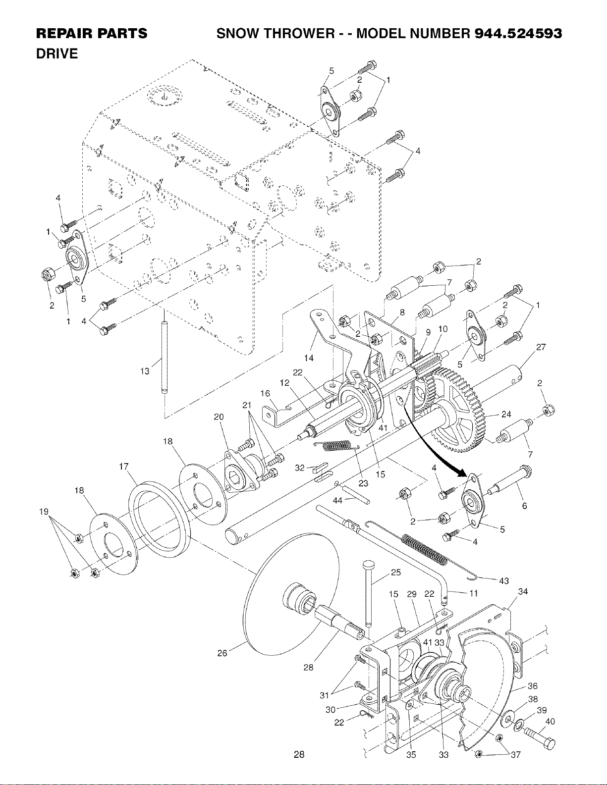
REPAIR PARTS
DRIVE
SNOW THROWER - - MODEL NUMBER 944.524593
KEY PART
NO. NO.
1 198584
2 751153
4 198584
5 180017
6 180134
7 179270
8 192616X479
9 180082
10 180065
11 187714
12 180066
13 178807
14 178619X479
15 175344
16 186951X479
17 179831
18 198176X479
19 73930500
20 178613
21 74760514
22 85179
23 180135
24 180081
25 178695
26 197763
27 404307
28 197764
29 175350X479
30 175349X479
31 72270505
32 189282
33 188909
34 175338X479
35 182504
36 191080
37 198541
38 19111507
39 198552
40 74950512
41 12000012
43 179095
44 9465M
DESCRIPTION
Screw, Hex Head 5/16-18 x 3/4
Nut, Lock 5/16-18
Screw, Hex Head 5/16-18 x 1/2
Bearing, Flange
Shaft, Auxiliary
Spacer, Plate
Plate, Auxiliary
Gear, Intermediate (12/58)
Gear, Pinion
Rod, Clutch
Shaft, Long, Hex
Pin, Pivot
Lever, Shifter / Wheel
Trunnion Bearing Assembly
Bracket, Pivot, Shifter
Ring, Rubber Wheel
Plate, Rubber Wheel
Nut, Lock 5/16-18
Hub, Rubber Wheel
Screw, Hex Head 5/16-18 x 7/8
Retainer, Hairpin
Spring, Bias
Gear, Axle (58 Teeth)
Pin, Pivot Lever
Plate Assembly, Drive
Shaft, Axle
Shaft, Short Hex
Lever, Shifter Plate
Bracket, Shifter Support
Bolt, Carriage 5/16-18 x 5/8
Key, Square 1/4 x 1/4 x 7/8
Bearing, Flange
Plate, Drive Mounting
Spacer, Bearing
Pulley, Traction Drive
Nut, Lock 5/16-18
Washer, Flat
Washer, Lock 5/16
Screw, Hex Head 5/16-18 x 3/4
Ring, Retaining
Spring, Return
Pin, Roll
NOTE: All component dimensions given in U.S. inches. 1 inch = 25.4 mm
IMPORTANT: Use only Original Equipment Manufacturer (O.E.M.) replacement parts.
Failure to do so could be hazardous, damage your snow thrower and void your warranty.
29
REPAIR PARTS SNOW THROWER -- MODEL NUMBER 944.524593
CHASSIS / ENGINE / PULLEYS
3O
31 37
36
29
39
56
\
\
43 42 _i>
j3
19
6
9
1
22
23
18 2O
24
58
26
27
41
34
35
52
51
11
11
L
46
44
45
30
47
/
/
15
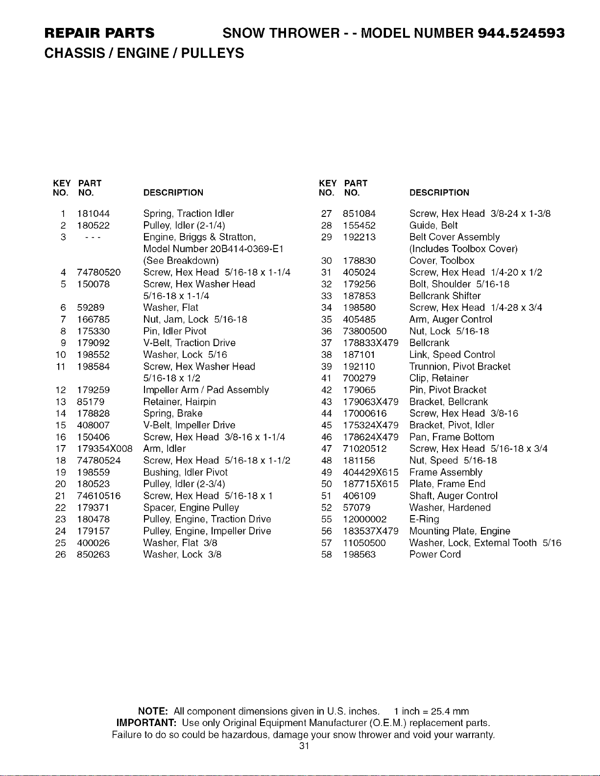
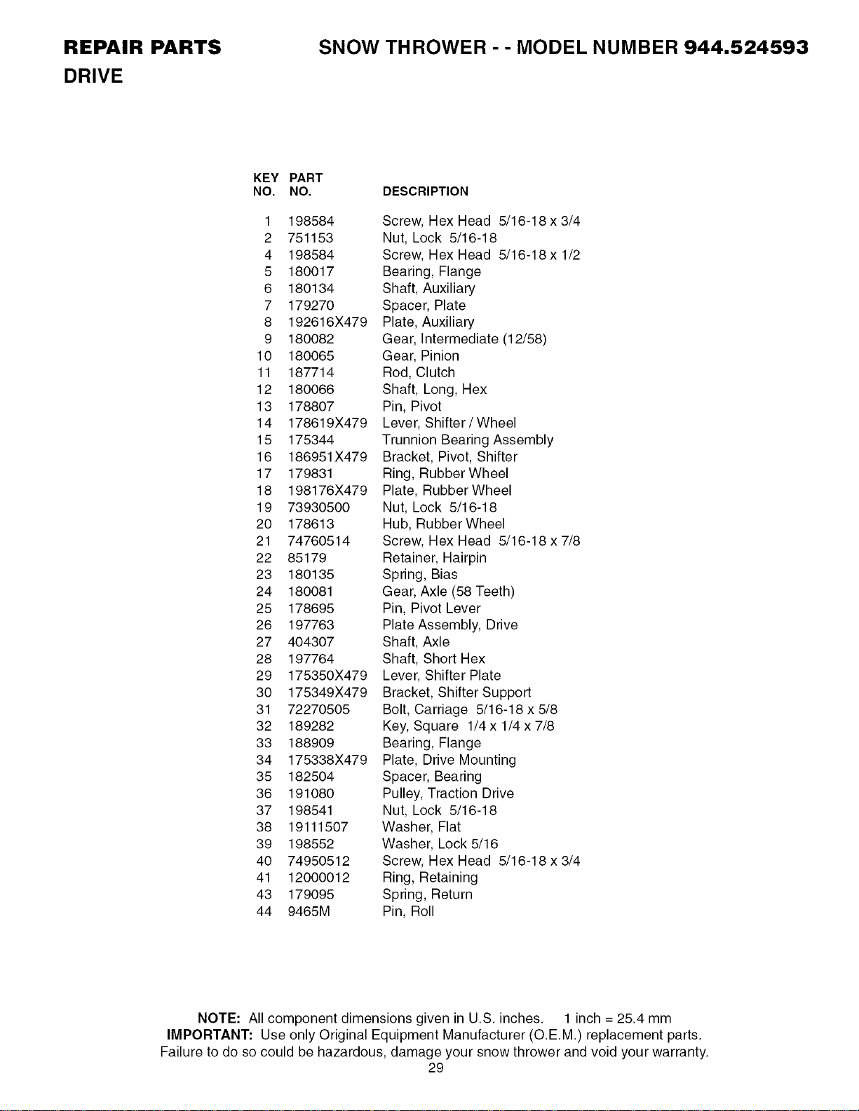
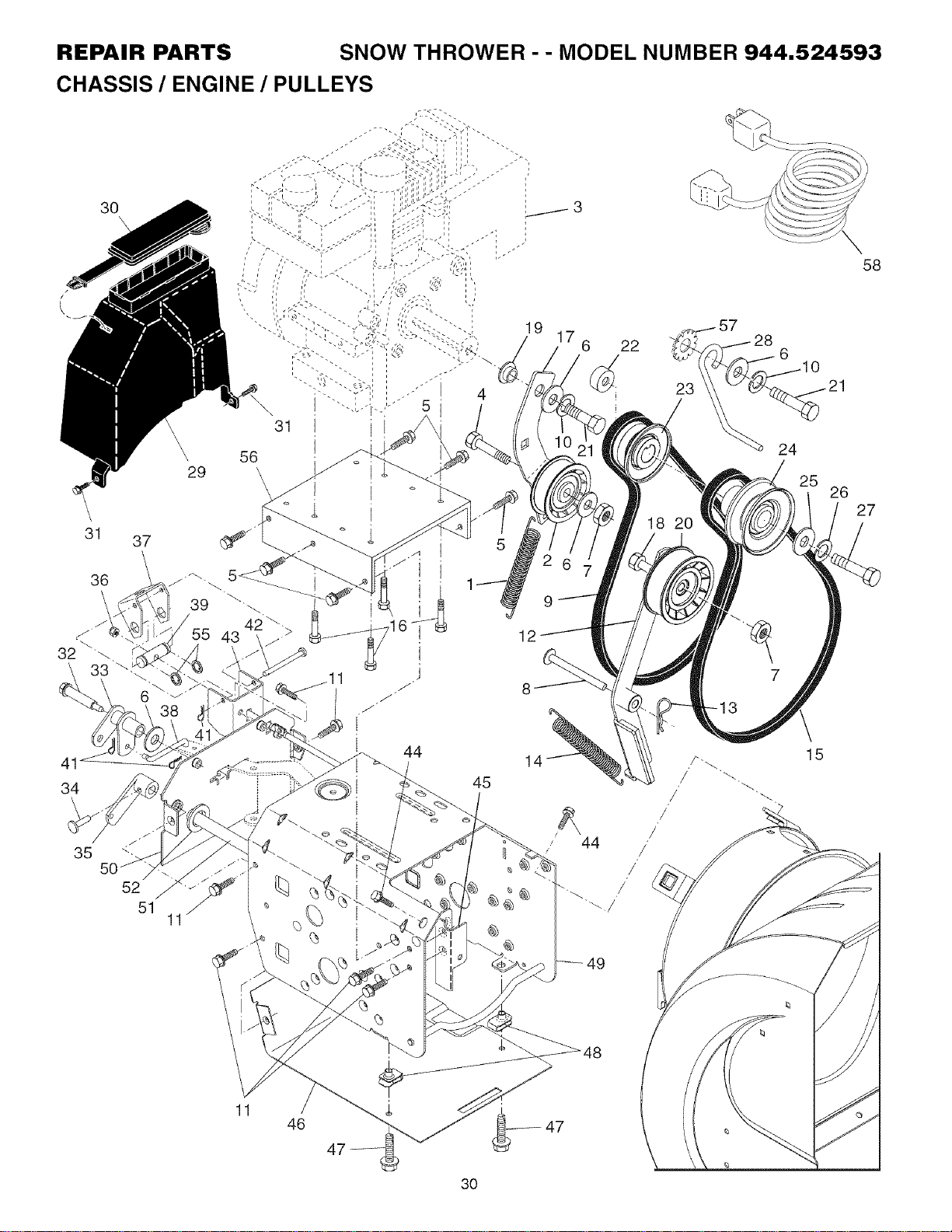
REPAIR PARTS SNOW THROWER - - MODEL NUMBER 944.524593
CHASSIS / ENGINE / PULLEYS
KEY PART KEY PART
NO. NO. DESCRIPTION NO. NO. DESCRIPTION
1 181044
2 180522
3 - - -
4 74780520
5 150078
6 59289
7 166785
8 175330
9 179092
10 198552
11 198584
12 179259
13 85179
14 178828
15 408007
16 150406
17 179354X008
18 74780524
19 198559
20 180523
21 74610516
22 179371
23 180478
24 179157
25 400026
26 850263
Spring, Traction Idler 27 851084
Pulley, Idler (2-1/4) 28 155452
Engine, Briggs & Stratton, 29 192213
Model Number 20B414-0369-E1
(See Breakdown) 30 178830
Screw, Hex Head 5/16-18 x 1-1/4 31 405024
Screw, Hex Washer Head 32 179256
5/16-18 x 1-1/4 33 187853
Washer, Flat 34 198580
Nut, Jam, Lock 5/16-18 35 405485
Pin, Idler Pivot 36 73800500
V-Belt, Traction Drive 37 178833X479
Washer, Lock 5/16 38 187101
Screw, Hex Washer Head 39 192110
5/16-18 x 1/2 41 700279
Impeller Arm / Pad Assembly 42 179065
Retainer, Hairpin 43 179063X479
Spring, Brake 44 17000616
V-Belt, Impeller Drive 45 175324X479
Screw, Hex Head 3/8-16 x 1-1/4 46 178624X479
Arm, Idler 47 71020512
Screw, Hex Head 5/16-18 x 1-1/2 48 181156
Bushing, Idler Pivot 49 404429X615
Pulley, Idler (2-3/4) 50 187715X615
Screw, Hex Head 5/16-18 x 1 51 406109
Spacer, Engine Pulley 52 57079
Pulley, Engine, Traction Drive 55 12000002
Pulley, Engine, Impeller Drive 56 183537X479
Washer, Flat 3/8 57 11050500
Washer, Lock 3/8 58 198563
Screw, Hex Head 3/8-24 x 1-3/8
Guide, Belt
Belt Cover Assembly
(Includes Toolbox Cover)
Cover, Toolbox
Screw, Hex Head 1/4-20 x 1/2
Bolt, Shoulder 5/16-18
Bellcrank Shifter
Screw, Hex Head 1/4-28 x 3/4
Arm, Auger Control
Nut, Lock 5/16-18
Bellcrank
Link, Speed Control
Trunnion, Pivot Bracket
Clip, Retainer
Pin, Pivot Bracket
Bracket, Bellcrank
Screw, Hex Head 3/8-16
Bracket, Pivot, Idler
Pan, Frame Bottom
Screw, Hex Head 5/16-18 x 3/4
Nut, Speed 5/16-18
Frame Assembly
Plate, Frame End
Shaft, Auger Control
Washer, Hardened
E-Ring
Mounting Plate, Engine
Washer, Lock, External Tooth 5/16
Power Cord
NOTE: All component dimensions given in U.S. inches. 1 inch = 25.4 mm
IMPORTANT: Use only Original Equipment Manufacturer (O.E.M.) replacement parts.
Failure to do so could be hazardous, damage your snow thrower and void your warranty.
31
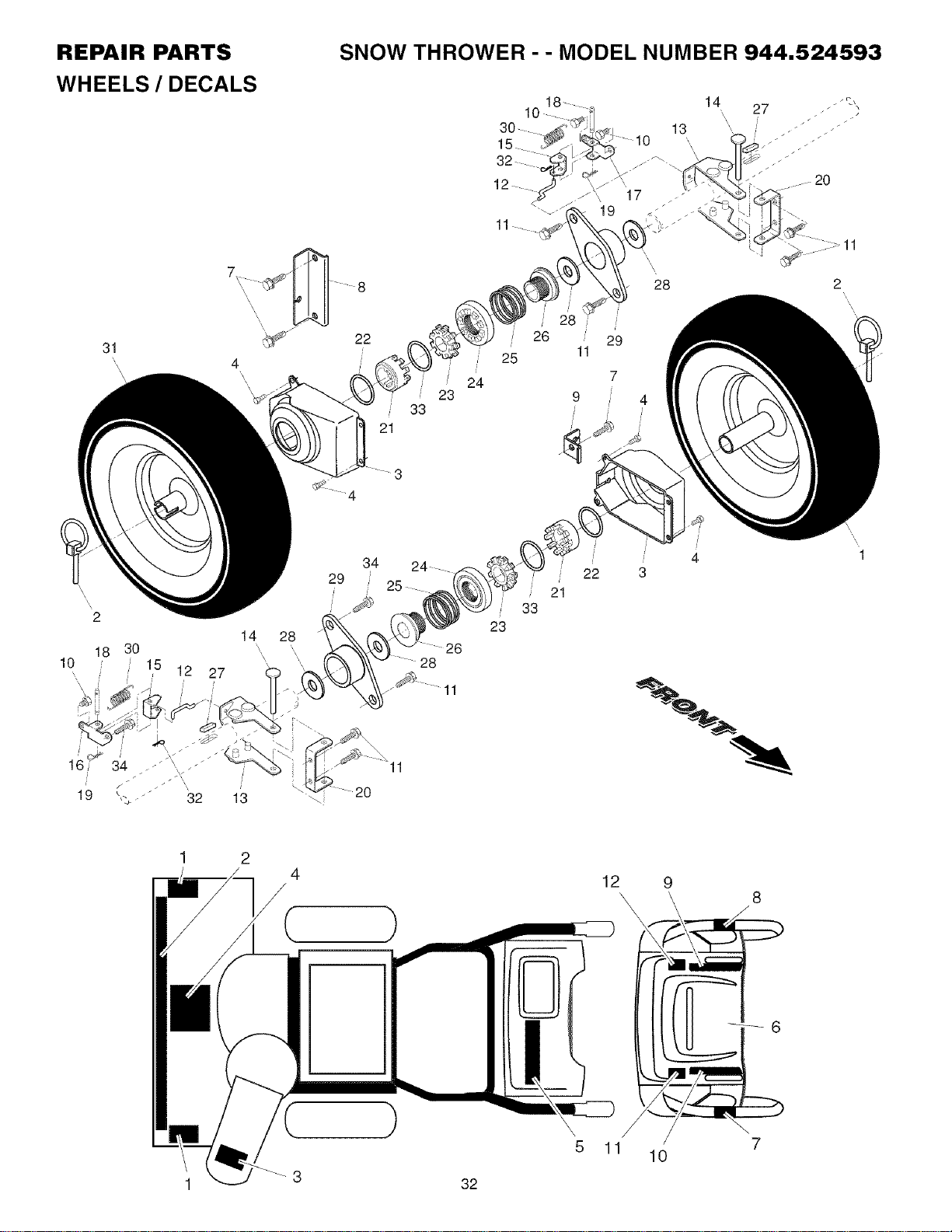
REPAIR PARTS SNOW THROWER -- MODEL NUMBER 944.524593
WHEELS / DECALS
31
\
21
3
23
33
30
5.
32
12
26
25
24
,\
19
7
9 4
14 27 _
\ •
20
2
\
\
\
\
\\
2
18 30
10
19
15 12 27
/
14 28
\ ',
13 "\!
34 24-
29
25
/
.... 26
28
11
20
21
33
23
22
4
3
1
12
\
5 11
10
7
1 3 32
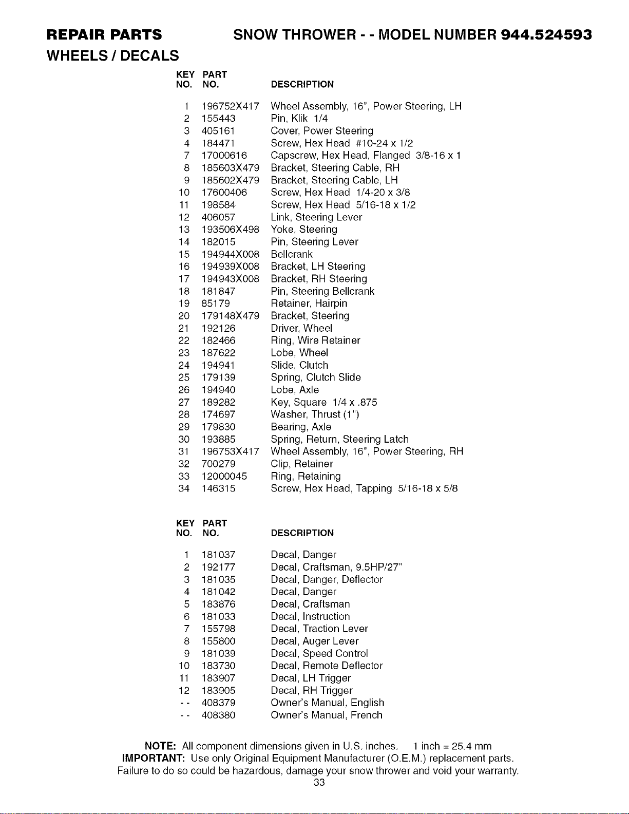
REPAIR PARTS
WHEELS / DECALS
KEY
NO.
1
2
3
4
7
8
9
10
11
12
13
14
15
16
17
18
19
20
21
22
23
24
25
26
27
28
29
30
31
32
33
34
SNOW THROWER - - MODEL NUMBER 944.524593
PART
NO.
196752X417
155443
405161
184471
17000616
185603X479
185602X479
17600406
198584
406057
193506X498
182015
194944X008
194939X008
194943X008
181847
85179
179148X479
192126
182466
187622
194941
179139
194940
189282
174697
179830
193885
196753X417
700279
12000045
146315
DESCRIPTION
Wheel Assembly, 16", Power Steering, LH
Pin, Klik 1/4
Cover, Power Steering
Screw, Hex Head #10-24 x 1/2
Capscrew, Hex Head, Flanged 3/8-16 x 1
Bracket, Steering Cable, RH
Bracket, Steering Cable, LH
Screw, Hex Head 1/4-20 x 3/8
Screw, Hex Head 5/16-18 x 1/2
Link, Steering Lever
Yoke, Steering
Pin, Steering Lever
Bellcrank
Bracket, LH Steering
Bracket, RH Steering
Pin, Steering Bellcrank
Retainer, Hairpin
Bracket, Steering
Driver, Wheel
Ring, Wire Retainer
Lobe, Wheel
Slide, Clutch
Spring, Clutch Slide
Lobe, Axle
Key, Square 1/4 x .875
Washer, Thrust (1")
Bearing, Axle
Spring, Return, Steering Latch
Wheel Assembly, 16", Power Steering, RH
Clip, Retainer
Ring, Retaining
Screw, Hex Head, Tapping 5/16-18 x 5/8
KEY
NO.
PART
NO.
1 181037
2 192177
3 181035
4 181042
5 183876
6 181033
7 155798
8 155800
9 181039
10 183730
11 183907
12 183905
-- 408379
-- 408380
DESCRIPTION
Decal, Danger
Decal, Craftsman, 9.5HP/27"
Decal, Danger, Deflector
Decal, Danger
Decal, Craftsman
Decal, Instruction
Decal, Traction Lever
Decal, Auger Lever
Decal, Speed Control
Decal, Remote Deflector
Decal, LH Trigger
Decal, RH Trigger
Owner's Manual, English
Owner's Manual, French
NOTE: All component dimensions given in U.S. inches. 1 inch = 25.4 mm
IMPORTANT: Use only Original Equipment Manufacturer (O.E.M.) replacement parts.
Failure to do so could be hazardous, damage your snow thrower and void your warranty.
33
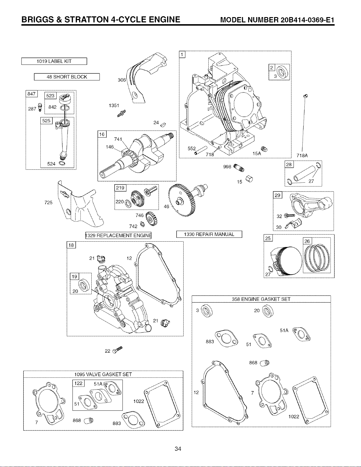
BRIGGS & STRATTON 4-CYCLE ENGINE MODEL NUMBER 20B414-O369-E1
1019 LABEL KIT I
I 48 SHORT BLOCK
524
I 306
1351
741
24<_
725
746
742 _'_Y
_329 REPLACEMENT ENGINE_
21 _ 12
1095 VALVE GASKET SET
122 51A_
868 (_ 883(_
552_718
I 1330 REPAIR MANUAL I
718A
32
358 ENGINE GASKET SET
2o@
883(_ 51_ 51A _
868_
12 7
®
1022
34
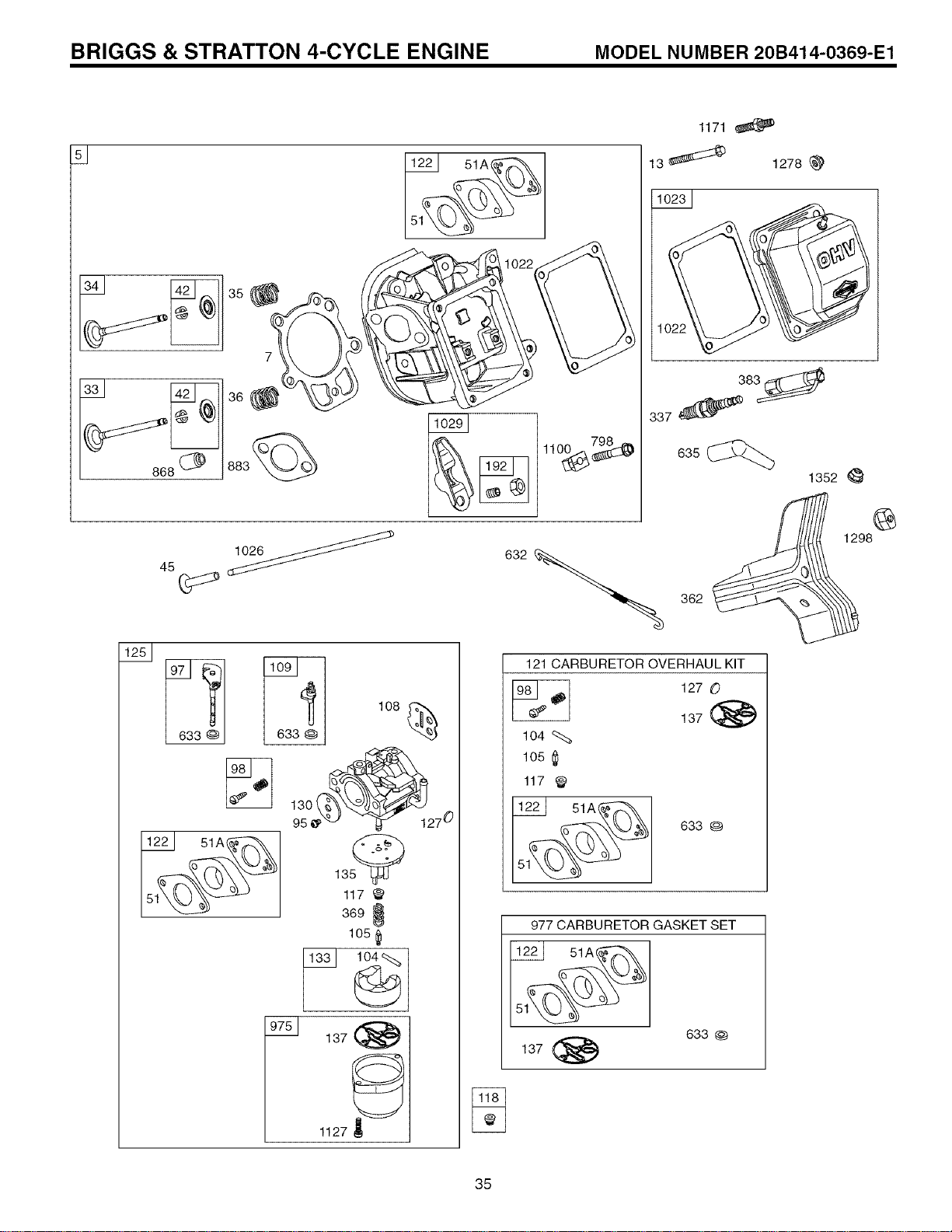
BRIGGS & STRATTON 4-CYCLE ENGINE MODEL NUMBER 20B414-O369-E1
122 51A_
S
122 51A_
108_
135
117 '_
369 _
105
137 (_
1127 ?
1171
13 _ 1278 _)
383_
337
835
1352 _'
121 CARBURETOR OVERHAUL KIT
104
105 I_
117
51A,x_
633 @
977 CARBURETOR GASKET SET
122 51A_
137 (_
633@
@
1298
35
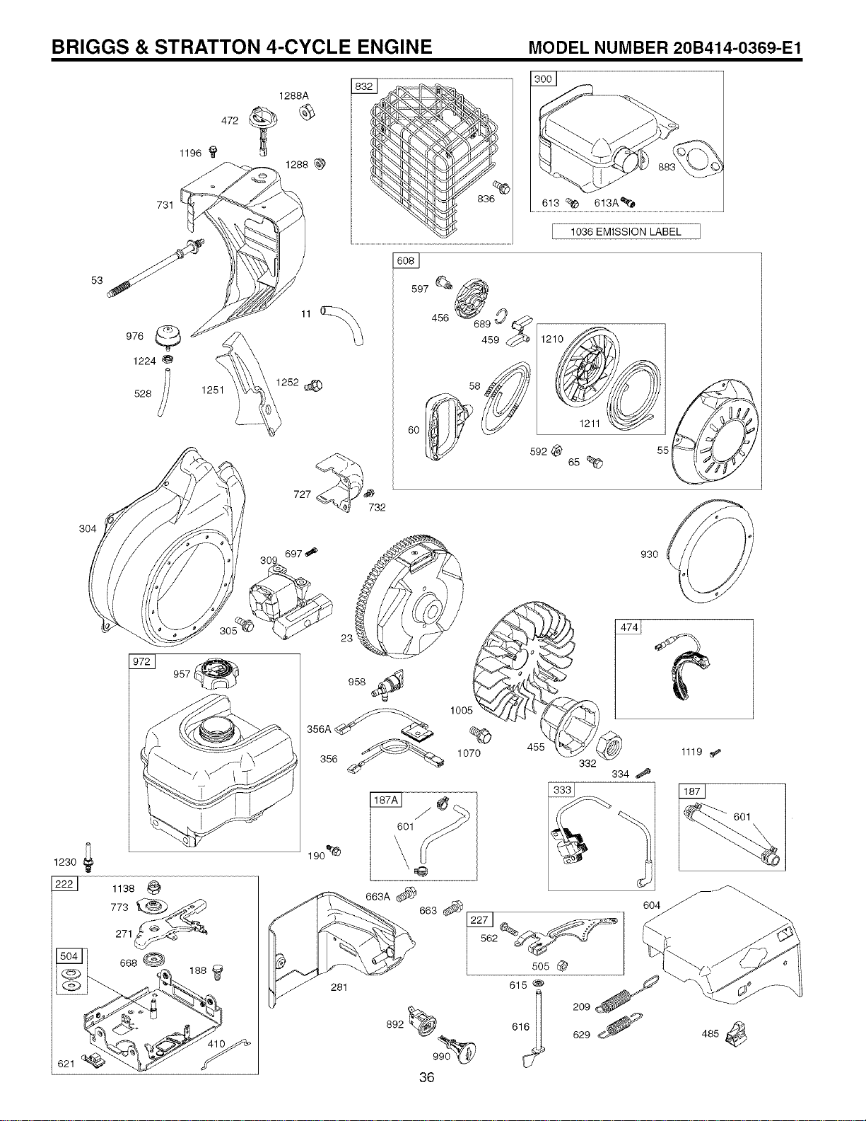
BRIGGS & STRATTON 4-CYCLE ENGINE MODEL NUMBER 20B414-O369-E1
304
1230
621
1288A
472 t _
1196 _
1288
731
978
1224
528 1251
972_ 957
1252_)
727
1036 EMISSION LABEL
597 _
48688;80S
1211
592 ,_
65
732
1
190 _
,@
663A
663
281
892 _990_
36
930
332
334 ,_
562-'___J_
505
615
616_
209
629 S
1119
601
488
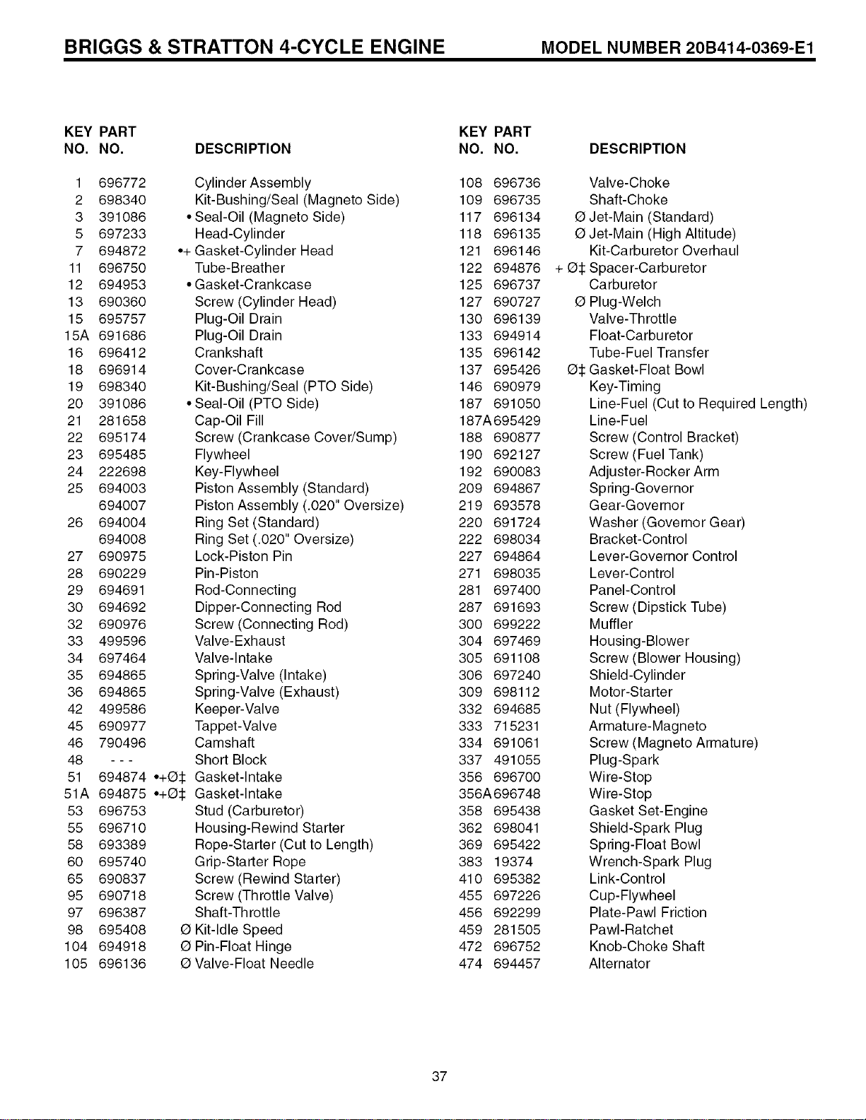
BRIGGS & STRATTON 4-CYCLE ENGINE MODEL NUMBER 20B414-O369-E1
KEY PART
NO. NO. DESCRIPTION
1 696772
2 698340
3 391086
5 697233
7 694872
11 696750
12 694953
13 690360
15 695757
15A 691686
16 696412
18 696914
19 698340
20 391086
21 281658
22 695174
23 695485
24 222698
25 694003
694007
26 694004
694008
27 690975
28 690229
29 694691
30 694692
32 690976
33 499596
34 697464
35 694865
36 694865
42 499586
45 690977
46 790496
48 ---
51 694874
51A 694875
53 696753
55 696710
58 693389
60 695740
65 690837
95 690718
97 696387
98 695408
104 694918
105 696136
Cylinder Assembly
Kit-Bushing/Seal (Magneto Side)
• Seal-Oil (Magneto Side)
Head-Cylinder
•+ Gasket-Cylinder Head
Tube-Breather
• Gasket-Crankcase
Screw (Cylinder Head)
Plug-Oil Drain
Plug-Oil Drain
Crankshaft
Cover-Crankcase
Kit-Bushing/Seal (PTO Side)
• Seal-Oil (PTO Side)
Cap-Oil Fill
Screw (Crankcase Cover/Sump)
Flywheel
Key-Flywheel
Piston Assembly (Standard)
Piston Assembly (.020" Oversize)
Ring Set (Standard)
Ring Set (.020" Oversize)
Lock-Piston Pin
Pin-Piston
Rod-Connecting
Dipper-Connecting Rod
Screw (Connecting Rod)
Valve-Exhaust
Valve-Intake
Spring-Valve (Intake)
Spring-Valve (Exhaust)
Keeper-Valve
Tappet-Valve
Camshaft
Short Block
•+a:l: Gasket-Intake
•+05 Gasket-Intake
Stud (Carburetor)
Housing-Rewind Starter
Rope-Starter (Cut to Length)
Grip-Starter Rope
Screw (Rewind Starter)
Screw (Throttle Valve)
Shaft-Throttle
0 Kit-Idle Speed
0 Pin-Float Hinge
0 Valve-Float Needle
KEY PART
NO. NO.
108 696736
109 696735
117 696134
118 696135
121 696146
122 694876
125 696737
127 690727
130 696139
133 694914
135 696142
137 695426
146 690979
187 691050
187A695429
188 690877
190 692127
192 690083
209 694867
219 693578
220 691724
222 698034
227 694864
271 698035
281 697400
287 691693
300 699222
304 697469
305 691108
306 697240
309 698112
332 694685
333 715231
334 691061
337 491055
356 696700
356A696748
358 695438
362 698041
369 695422
383 19374
410 695382
455 697226
456 692299
459 281505
472 696752
474 694457
DESCRIPTION
Valve-Choke
Shaft-Choke
0 Jet-Main (Standard)
0 Jet-Main (High Altitude)
Kit-Carburetor Overhaul
+ 05 Spacer-Carburetor
Carburetor
0 Plug-Welch
Valve-Throttle
Float-Carbu retor
Tube-Fuel Transfer
05 Gasket-Float Bowl
Key-Timing
Line-Fuel (Cut to Required Length)
Line-Fuel
Screw (Control Bracket)
Screw (Fuel Tank)
Adjuster-Rocker Arm
Spring-Governor
Gear-Governor
Washer (Governor Gear)
Bracket-Control
Lever-Governor Control
Lever-Control
Panel-Control
Screw (Dipstick Tube)
Muffler
Housing-Blower
Screw (Blower Housing)
Shield-Cylinder
Motor-Starter
Nut (Flywheel)
Armature-Magneto
Screw (Magneto Armature)
Plug-Spark
Wire-Stop
Wire-Stop
Gasket Set-Engine
Shield-Spark Plug
Spring-Float Bowl
Wrench-Spark Plug
Link-Control
Cup-Flywheel
Plate-Pawl Friction
PawI-Ratchet
Knob-Choke Shaft
Alternator
37
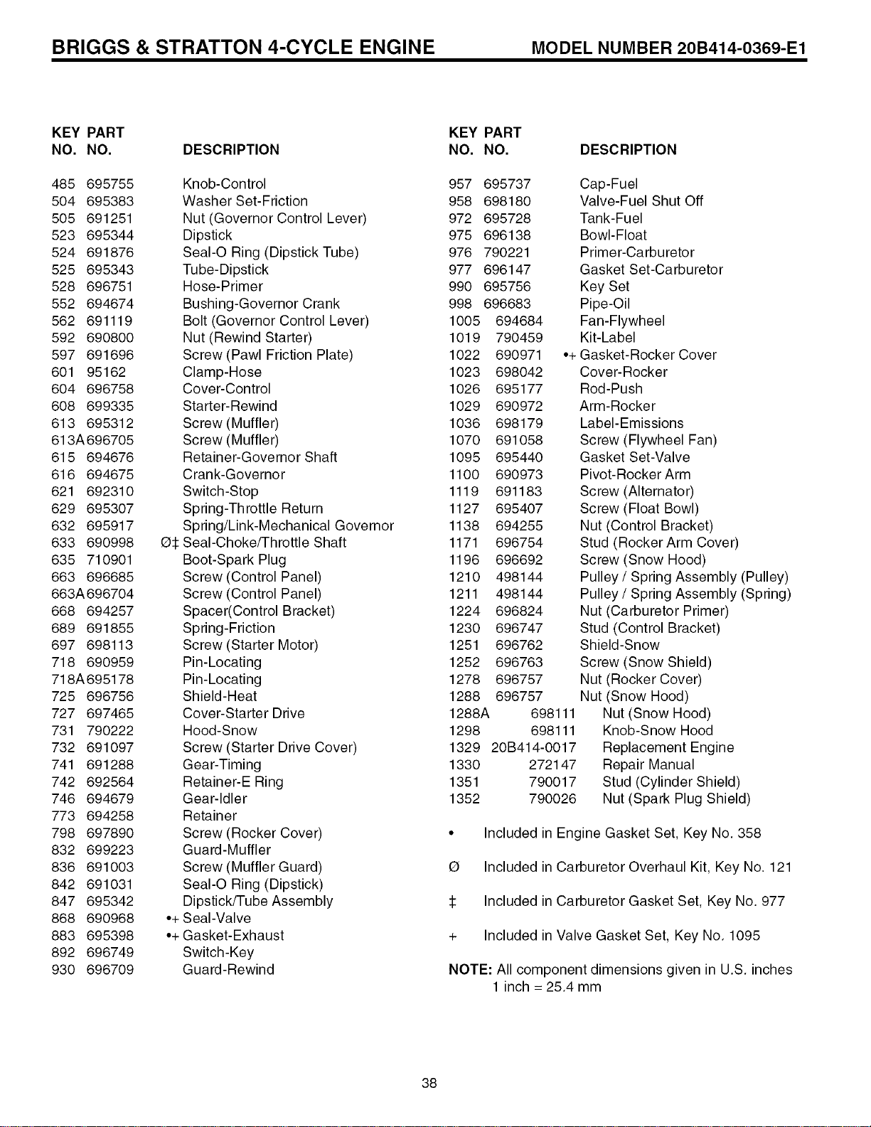
BRIGGS & STRATTON 4-CYCLE ENGINE MODEL NUMBER 20B414-O369-E1
KEY PART
NO. NO. DESCRIPTION
485 695755 Knob-Control
504 695383 Washer Set-Friction
505 691251 Nut (Governor Control Lever)
523 695344 Dipstick
524 691876 Seal-O Ring (Dipstick Tube)
525 695343 Tube-Dipstick
528 696751 Hose-Primer
552 694674 Bushing-Governor Crank
562 691119 Bolt (Governor Control Lever)
592 690800 Nut (Rewind Starter)
597 691696 Screw (Pawl Friction Plate)
601 95162 Clamp-Hose
604 696758 Cover-Control
608 699335 Starter-Rewind
613 695312 Screw (Muffler)
613A 696705 Screw (Muffle r)
615 694676 Retainer-Governor Shaft
616 694675 Crank-Governor
621 692310 Switch-Stop
629 695307 Spring-Throttle Return
632 695917 Spring/Link-Mechanical Governor
633 690998 O:l:SeaI-Choke/Throttle Shaft
635 710901 Boot-Spark Plug
663 696685 Screw (Control Panel)
663A696704 Screw (Control Panel)
668 694257 Spacer(Control Bracket)
689 691855 Spring-Friction
697 698113 Screw (Starter Motor)
718 690959 Pin-Locating
718A695178 Pin-Locating
725 696756 Shield-Heat
727 697465 Cover-Starter Drive
731 790222 Hood-Snow
732 691097 Screw (Starter Drive Cover)
741 691288 Gear-Timing
742 692564 Retainer-E Ring
746 694679 Gear-Idler
773 694258 Retainer
798 697890 Screw (Rocker Cover)
832 699223 Guard-Muffler
836 691003 Screw (Muffler Guard)
842 691031 Seal-O Ring (Dipstick)
847 695342 Dipstick/Tube Assembly
868 690968 .+ Seal-Valve
883 695398 •+ Gasket-Exhaust
892 696749 Switch-Key
930 696709 Guard-Rewind
KEY PART
NO. NO. DESCRIPTION
957 695737 Cap-Fuel
958 698180 Valve-Fuel Shut Off
972 695728 Tank-Fuel
975 696138 Bowl-Float
976 790221 Primer-Carburetor
977 696147 Gasket Set-Carburetor
990 695756 Key Set
998 696683 Pipe-Oil
1005 694684 Fan-Flywheel
1019 790459 Kit-Label
1022 690971 •+ Gasket-Rocker Cover
1023 698042 Cover-Rocker
1026 695177 Rod-Push
1029 690972 Arm-Rocker
1036 698179 Label-Emissions
1070 691058 Screw (Flywheel Fan)
1095 695440 Gasket Set-Valve
1100 690973 Pivot-Rocker Arm
1119 691183 Screw (Alternator)
1127 695407 Screw (Float Bowl)
1138 694255 Nut (Control Bracket)
1171 696754 Stud (Rocker Arm Cover)
1196 696692 Screw (Snow Hood)
1210 498144 Pulley / Spring Assembly (Pulley)
1211 498144 Pulley / Spring Assembly (Spring)
1224 696824 Nut (Carburetor Primer)
1230 696747 Stud (Control Bracket)
1251 696762 Shield-Snow
1252 696763 Screw (Snow Shield)
1278 696757 Nut (Rocker Cover)
1288 696757 Nut (Snow Hood)
1288A 698111 Nut (Snow Hood)
1298 698111 Knob-Snow Hood
1329 20B414-0017 Replacement Engine
1330 272147 Repair Manual
1351 790017 Stud (Cylinder Shield)
1352 790026 Nut (Spark Plug Shield)
• Included in Engine Gasket Set, Key No. 358
0 Included in Carburetor Overhaul Kit, Key No. 121
:1: Included in Carburetor Gasket Set, Key No. 977
+ Included in Valve Gasket Set, Key No. 1095
NOTE: All component dimensions given in U.S. inches
1 inch = 25.4 mm
38

SERVICE NOTES
39

Just Call:
1-800-4-MY-HOME ®
(1-800-469-4663)
24 hours a day, 7 days a week
For the repair of major brand appliances in your own home...
no matter who made it, no matter who sold it!
For your nearest Sears Parts and Service location,
to bring in products like vacuums, lawn equipment and electronics.
For Sears Parts & Service, to order the replacement parts,
accessories and owner's manuals that you need to do-it-yourself.
www.sears.ca
To purchase or inquire about a Sears Maintenance Agreement, call:
1-800-361-6665
9 a.m.-11 p.m. Mon. - Fri., EST, 9 a.m. - 4 p.m. Sat.
Pour service en fran(_ais:
1-800-LE-FOYER Mc
(1-800-533-6937)
www.sears.ca
02488e
_) / TMTrademarks of Sears, Roebuck and Co. used under license by Sears Canada
MDMarquedepos6e / MCMarque de commerce de Sears, Roebuck and Co. utilis6e en vertu d'une licence de Sears Canada
408379 08.16.06 BY Printed in U.S.A.


