Loading ...
Loading ...
Loading ...
10
Important ! - For single phase units, oil level
should be below capacitor
Seal Chamber (DS Units Only)- Set unit on its side, with
plug (44) upward, and refi ll with new oil as per Table 1 (see
parts list for amount). Apply pipe thread compound to threads
of pipe plug (44) and assemble to outer seal plate (29).
Warning ! - Do not overfi ll oil. Overfi lling of
motor housing with oil can create excessive
and dangerous hydraulic pressure which
can destroy the pump and create a hazard.
Overfi lling oil voids warranty.
TABLE 1 - COOLING OIL - Dielectric
SUPPLIER GRADE
BP Enerpar SE100
Conoco Pale Paraffi n 22
Mobile D.T.E. Oil Light
G & G Oil Circulating 22
Imperial Oil Voltesso-35
Shell Canada Transformer-10
Texaco Diala-Oil-AX
Woco Premium 100
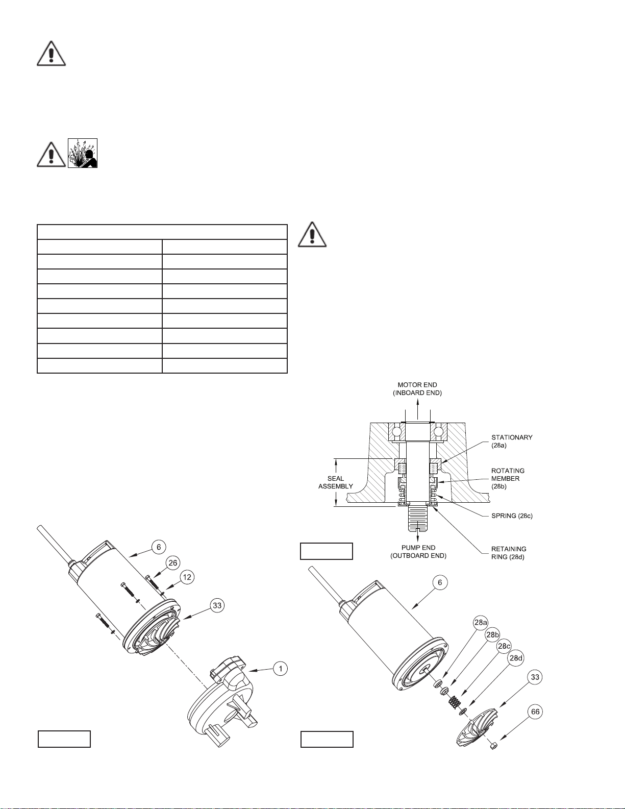
F-2) Impeller and Volute Service:
F-2.1) Disassembly and Inspection:
To clean out volute (1) or replace impeller (33), disconnect
power, remove hex bolts (26), and lockwasher (12), vertically
lift motor and seal plate assembly from volute (1) and spacer
ring (31), see Figure 3. Clean out body if necessary. Clean
and examine impeller (33), for pitting or wear and replace if
required, inspect gasket (36) and replace if cut or damaged.
If the impeller (33) needs replacing, place a fl at screwdriver in
the slot of the end of the shaft to hold the shaft stationary while
unscrewing the jam nut (66) and impeller (33).
F-2.2) Reassembly:
To install impeller (33), clean the threads with thread locking
compound cleaner. Apply removable Loctite® 603 or equivalent
to shaft threads. Screw impeller onto the shaft hand tight while
using a screwdriver in the slot at the end of the shaft to hold it
stationary. Apply thread locking compound (57) to shaft threads
then install jam nut (66) and torque to 40 ft. lbs. It is important
that the spring of the lower shaft seal (28) seats in the hub of
the impeller (33). Rotate impeller to check for binding. Position
gasket (36) on volute fl ange and place spacer ring (31) over it.
Place another gasket (36) on spacer ring and position impeller
and motor housing on spacer ring (31). Position lockwasher
(12) on cap screw (26) and screw into volute (1). Torque to 100
in-lbs. Check for free rotation of motor and impeller.
F-3) Shaft Seal Service:
Important ! - Handle seal parts with extreme care.
DO NOT scratch or mar lapped surfaces.
F-3.1) Disassembly and Inspection:
Outer Seal (All Units)- To expose shaft seal (28) for
examination, disassemble volute and impeller as outlined in
paragraph F-2.1. If further repair is required, remove retaining
ring (28d), spring (28c) and rotating member (28b) from shaft
(see Figures 4 & 5). Examine all seal parts and especially
contact faces. Inspect seal for signs of wear such as uneven
wear pattern on stationary members, chips and scratches
on either seal face. DO NOT interchange seal components,
replace the entire shaft seal (28). If replacing seal, remove
stationary (28a) by prying out with fl at screwdriver.
FIGURE 3
FIGURE 5
FIGURE 4
Loading ...
Loading ...
Loading ...