A Crane Co. Company
BARNES
BARNES
®
INSTALLATION and OPERATION MANUAL
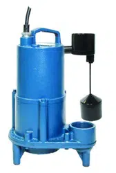
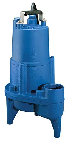
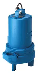
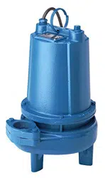
Submersible Sewage Ejector
IMPORTANT! Read all instructions in this manual before operating pump.
As a result of Crane Pumps & Systems, Inc., constant product improvement program,
product changes may occur. As such Crane Pumps & Systems reserves the right to
change product without prior written notifi cation.
420 Third Street 83 West Drive, Bramton
Piqua, Ohio 45356 Ontario, Canada L6T 2J6
Phone: (937) 778-8947 Phone: (905) 457-6223
Fax: (937) 773-7157 Fax: (905) 457-2650
www.cranepumps.com
Form No. 115941-Rev. T
Series: 2SEV & 3SEV, L & DS
1.5 & 2 HP, 3450 RPM, 60 Hz.
Single and Double Seal
Manual Index

2
TABLE OF CONTENTS
SAFETY FIRST ............................................................................................... 3
A. PUMP SPECIFICATIONS ................................................................................4 - 5
B. GENERAL INFORMATION ..............................................................................6
C. INSTALLATION ................................................................................................6 - 7
ELECTRICAL DATA .........................................................................................8
D. START-UP OPERATION ..................................................................................7 - 8
E. PREVENTATIVE MAINTENANCE ...................................................................9
F. SERVICE and REPAIR ....................................................................................9 - 14
G. REPLACEMENT PARTS ..................................................................................15
TROUBLE SHOOTING ....................................................................................16
SINGLE SEAL - CROSS-SECTION (Fig. 15) ..................................................17
SINGLE SEAL - EXPLODED VIEW (Fig. 16) ..................................................18
DOUBLE SEAL - CROSS-SECTION (Fig. 17) .................................................19
DOUBLE SEAL - EXPLODED VIEW (Fig. 18) .................................................20
PARTS LIST ...................................................................................................21 - 22
RETURNED GOODS POLICY .........................................................................23
WARRANT
START-UP REPORT
WARRANTY REGISTRATION
SPECIAL TOOLS AND EQUIPMENT
INSULATION TESTER (MEGGER)
DIELECTRIC TESTER
SEAL TOOL KIT ( see parts list)
PRESSURE GAUGE KIT (see parts list)
Other brand and product names are trademarks or registered trademarks of their respective holders.
® Barnes is a registered trademark of Crane Pumps & Systems, Inc
11/03, 6/05, 5/06, 9/06 Alteration Rights Reserved
3
Please Read This Before Installing Or Operating Pump.
This information is provided for SAFETY and to PREVENT
EQUIPMENT PROBLEMS. To help recognize this information,
observe the following symbols:
IMPORTANT! Warns about hazards that can result
in personal injury or Indicates factors concerned with
assembly, installation, operation, or maintenance which
could result in damage to the machine or equipment if
ignored.
CAUTION ! Warns about hazards that can or will cause minor
personal injury or property damage if ignored. Used with symbols
below.
WARNING ! Warns about hazards that can or will cause serious
personal injury, death, or major property damage if ignored. Used
with symbols below.
Only qualifi ed personnel should install, operate and repair
pump. Any wiring of pumps should be performed by a qualifi ed
electrician.
WARNING ! - To reduce risk of electrical shock, pumps
and control panels must be properly grounded in
accordance with the National Electric Code (NEC) or the
Canadian Electrical Code (CEC) and all applicable state,
province, local codes and ordinances.
WARNING! - To reduce risk of electrical shock, always
disconnect the pump from the power source before
handling or servicing. Lock out power and tag.
WARNING! Operation against a closed
discharge valve will cause premature bearing
and seal failure on any pump, and on end
suction and self priming pump the heat build
may cause the generation of steam with resulting dangerous
pressures. It is recommended that a high case temperature
switch or pressure relief valve be installed on the pump body.
CAUTION ! Never operate a pump with a plug-in type
power cord without a ground fault circuit interrupter.
CAUTION! Pumps build up heat and pressure
during operation-allow time for pumps to cool
before handling or servicing.
WARNING! - DO NOT pump hazardous materials
(fl ammable, caustic, etc.) unless the pump is specifi cally
designed and designated to handle them.
Do not block or restrict discharge hose, as discharge
hose may whip under pressure.
WARNING! - DO NOT wear loose clothing that may
become entangled in the impeller or other moving parts.
WARNING! - Keep clear of suction and discharge
openings. DO NOT insert fi ngers in pump with power
connected.
Always wear eye protection when working on pumps.
Make sure lifting handles are securely fastened each
time before lifting. DO NOT operate pump without
safety devices in place. Always replace safety devices
that have been removed during service or repair.
Secure the pump in its operating position so it can not
tip over, fall or slide.
DO NOT exceed manufacturers recommendation for
maximum performance, as this could cause the motor
to overheat.
DO NOT remove cord and strain relief. Do not connect
conduit to pump.
WARNING! Cable should be protected at all times to
avoid punctures, cut, bruises and abrasions - inspect
frequently. Never handle connected power cords with
wet hands.
WARNING! To reduce risk of electrical shock, all wiring
and junction connections should be made per the NEC
or CEC and applicable state or province and local
codes. Requirements may vary depending on usage
and location.
WARNING! Submersible Pumps are not approved for
use in swimming pools, recreational water installations,
decorative fountains or any installation where human
contact with the pumped fl uid is common.
WARNING! Products Returned Must Be Cleaned,
Sanitized, Or Decontaminated As Necessary Prior
To Shipment, To Insure That Employees Will Not Be
Exposed To Health Hazards In Handling Said Material.
All Applicable Laws And Regulations Shall Apply.
Bronze/brass and bronze/brass fi tted pumps may
contain lead levels higher than considered safe for
potable water systems. Lead is known to cause cancer
and birth defects or other reproductive harm. Various
government agencies have determined that leaded
copper alloys should not be used in potable water
applications. For non-leaded copper alloy materials of
construction, please contact factory.
IMPORTANT! - Crane Pumps & Systems, Inc. is not
responsible for losses, injury, or death resulting from a
failure to observe these safety precautions, misuse or
abuse of pumps or equipment.
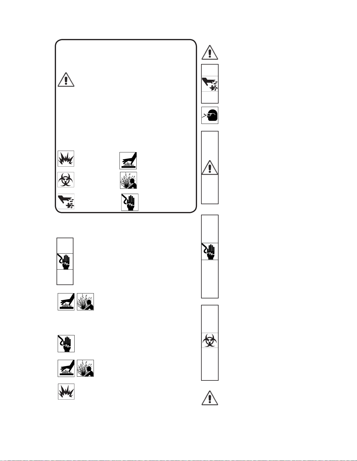
SAFETY FIRST!
Hazardous fl uids can
cause fi re or explo-
sions, burnes or death
could result.
Extremely hot - Severe
burnes can occur on contact.
Biohazard can cause
serious personal injury.
Hazardous fl uids can Hazard-
ous pressure, eruptions or ex-
plosions could cause personal
injury or property damage.
Rotating machinery
Amputation or severe
laceration can result.
Hazardous voltage can
shock, burn or cause death.
4
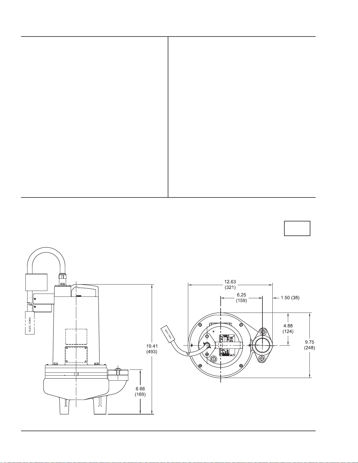
DISCHARGE .................. 2” NPT, Vertical, Bolt-on Flange
3” NPT, Vertical, Bolt-on Flange
LIQUID TEMPERATURE 104°F (40°C) Intermittent
MOTOR HOUSING ........ Cast Iron ASTM A-48, Class 30
VOLUTE ......................... Cast Iron ASTM A-48, Class 30
SEAL PLATE ................. Cast Iron ASTM A-48, Class 30
IMPELLER Design ...........Vortex, Open with Pump out vanes
on Back side. Dynamically
balanced, ISO G6.3
Material ........ 85-5-5-5 Cast Iron
SHAFT ............................ 416 Stainless Steel
SQUARE RINGS ............ Buna-N
HARDWARE .................. 300 Series Stainless Steel
PAINT ............................. Air dry enamel, top coat
SEAL Design .......... Single Mechanical, or Tandem
Mechanical with oil fi lled reservoir
Material ........ Rotating Faces - Carbon
Stationary Faces - Ceramic
Elastomer - Buna-N
Hardware - 300 series stainless steel
CORD ENTRY ................ 2” NPT - 20 Ft. (6.1m)
3” NPT - 30 Ft. (9.1m) Cord, Quick
connect. Custom molded for sealing
and strain relief
SPEED ........................... 3450 RPM, 60Hz (nominal)
UPPER BEARING:
Design .......... Single Row, Ball, Oil Lubricated
Load ............. Radial
LOWER BEARING:
Design .......... Single Row, Ball, Oil Lubricated
Load ............. Radial & Thrust
MOTOR: Design .......... NEMA L, Single phase,
NEMA B, Three Phase Torque Curve,
Oil Filled, Squirrel Cage Induction
Insulation ...... Class B
Class F on selected models
SINGLE PHASE ............. Permanent Split Capacitor (PSC)
Includes overload protection in motor
THREE PHASE .............. 200-240/480 is Tri voltage motor.
600V. Requires overload protection
to be included in control panel
OPTIONAL EQUIPMENT:
Seal Material, Impeller Trims, Additional Cord,
N/C Temperature Sensors with cord for 3 Phase pumps
(Requires relay in Control Panel). N/O Moisture Sensor with
cord for DS pumps (Requires relay in Control Panel), 3” NPT
Discharge Adapter
SECTION: A - PUMP SPECIFICATIONS:
inches
(mm)
2SEV-L Series
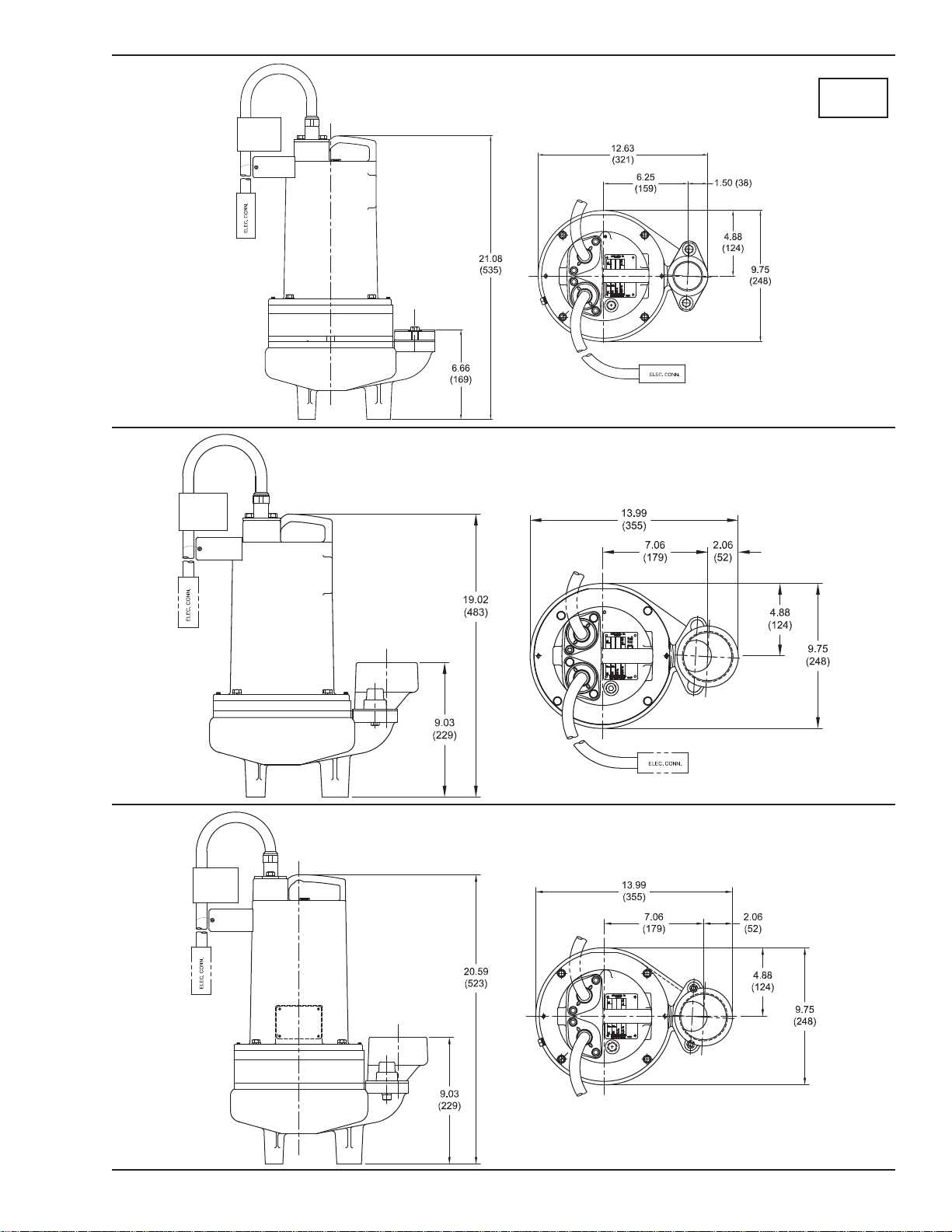
5
inches
(mm)
2SEV-DS Series
3SEV-L Series
3SEV-DS Series
6
SECTION B: GENERAL INFORMATION
B-1) To the Purchaser:
Congratulations! You are the owner of one of the fi nest pumps
on the market today. CP&S pumps are products engineered
and manufactured of high quality components. Over one
hundred years of pump building experience along with a
continuing quality assurance program combine to produce a
pump which will stand up to the toughest applications. This
manual will provide helpful information concerning installation,
maintenance, and proper service guidelines.
B-2) Receiving:
Upon receiving the pump, it should be inspected for damage
or shortages. If damage has occurred, fi le a claim immediately
with the company that delivered the pump. If the manual
is removed from the packaging, do not lose or misplace.
B-3) Storage:
Short Term- CP&S Pumps are manufactured for effi cient
performance following short inoperative periods in storage.
For best results, pumps can be retained in storage, as factory
assembled, in a dry atmosphere with constant temperatures
for up to six (6) months. Long Term- Any length of time
exceeding six (6) months, but not more than twenty-four (24)
months. The unit should be stored in a temperature controlled
area, a roofed over walled enclosure that provides protection
from the elements (rain, snow, wind-blown dust, etc.), and
whose temperature can be maintained between +40 deg. F
and +120 deg. F. (4.4 - 49°C). Pump should be stored in its
original shipping container. On initial start up, rotate impeller
by hand to assure seal and impeller rotate freely. If it is
required that the pump be installed and tested before the long
term storage begins, such installation will be allowed provided:
1.) The pump is not installed under water for more than
one (1) month.
2.) Immediately upon satisfactory completion of the test,
the pump is removed, thoroughly dried, repacked in the
original shipping container, and placed in a temperature
controlled storage area.
B-4) Service Centers:
For the location of the nearest Barnes Service Center, check
your Barnes representative or Crane Pumps & Systems, Inc.,
Service Department in Piqua, Ohio, telephone (937) 778-8947
or Crane Pumps & Systems Canada, in Brampton, Ontario,
(905) 457-6223.
SECTION C: INSTALLATION
C-1) Location:
These pumping units are self-contained and are recommended
for use in a sump, lift station or basin. The sump, lift station or
basin shall be vented in accordance with local plumbing codes.
This pump is designed to pump sewage, effl uent, or other
nonexplosive or noncorrosive wastewater. and shall NOT be
installed in locations classifi ed as hazardous in accordance
with the National Electrical Code (NEC), ANSI/NFPA 70 or the
Canadian Electrical Code (CEC). Never install the pump in a
trench, ditch or hole with a dirt bottom; the legs will sink into the
dirt and the suction will become plugged.
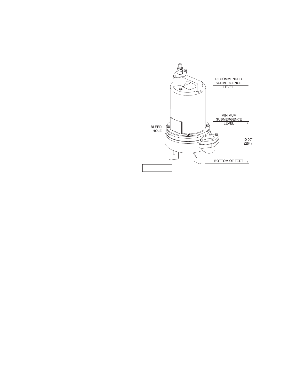
C-1.1) Submergence:
It is recommended that the pump be operated in the submerged
condition and the sump liquid level should never be less than
10 inches above the pump bottom (see Fig. 1). Please note
that the SEV Series Pumps contain a bleed hole just above
the volute that allows air to escape from the volute during
operation, liquid will spray from this hole.
C-2) Discharge:
Discharge piping should be as short as possible. Both a check
valve and a shut-off valve are recommended for each pump
being used. The check valve is used to prevent backfl ow
into the sump. Excessive backfl ow can cause fl ooding
and/or damage to the pump. The shut-off valve is used to
stop system fl ow during pump or check valve servicing.
Barnes Pumps supplies a Stainless Rail Package for the
2” models and also a variety of 2” and 3” break-away fi tting
discharge systems designed to allow the submersible
wastewater pump to be installed or removed without requiring
personnel to enter the wet well. Contact your local Barnes
Pumps distributor for complete details.
Stainless Rail Package (Not Shown)- The package system
comes complete and ready to place into the ground as outlined
in the project specifi cations. The moveable portion of the Break
Away Fitting (BAF), check valve, piping and guide bracket
comes assembled on the pump along with the lifting cord.
Insert pump bracket and moveable portion of BAF into the
guide channel and lower pump into basin (DO NOT DROP).
Now connect power and control cords to the junction box or
control panel depending on system design.
C-3) Liquid Level Controls:
The level controls are to be supported by a mounting bracket that
is attached to the sump wall, cover or junction box. Cord grips
are used to hold the cords in place on the mounting bracket.
The control level can be changed by loosening the grip and
adjusting the cord length as per the plans and specifi cations.
Be certain that the level controls cannot hang up or foul in it’s
swing and that the pump is completely submerged when the
level control is in the “Off” mode.
FIGURE 1
7
C-4) Electrical Connections:
An acceptable motor control switch shall be provided at the
time of installation.
C-4.1) Power and Control Cords:
The cord assembly mounted to the pump must not be modifi ed
in any way except for shortening to a specifi c application.
Any splice between the pump and the control panel must
be made in accordance with all applicord electric codes. It is
recommended that a junction box, if used, be mounted outside
the sump or be of at least Nema 4 (EEMAC-4) construction if
located within the wet well. DO NOT USE THE POWER OR
CONTROL CORD TO LIFT PUMP. NOTE: THE WHITE WIRE
IS NOT A NEUTRAL OR GROUND LEAD, BUT A POWER
CARRYING CONDUCTOR.
C-4.2) Overload Protection:
C-4.2-1) Three Phase (Optional) - The normally closed (N/C)
thermal sensor is embedded in the motor windings and will
detect excessive heat in the event an overload condition
occurs. The thermal sensor will trip when the windings become
too hot and will automatically reset itself when the pump motor
cools to a safe temperature. It is recommended that the
thermal sensor be connected in series to an alarm device to
alert the operator of an overload condition, and/or the motor
starter coil to stop the pump. In the event of an overload, the
source of this condition should be determined and rectifi ed
immediately. DO NOT LET THE PUMP CYCLE OR RUN IF
AN OVERLOAD CONDITION OCCURS !
C-4.2-2) Single Phase (Standard) - The type of in-winding
overload protector used is referred to as an inherent
overheating protector and operates on the combined effect
of temperature and current. This means that the overload
protector will trip out and shut the pump off if the windings
become too hot, or the load current passing through them
becomes too high. It will then automatically reset and start the
pump up after the motor cools to a safe temperature.
In the event of an overload, the source of this condition should
be determined and rectifi ed immediately. DO NOT LET THE
PUMP CYCLE OR RUN IF AN OVERLOAD CONDITION
OCCURS !
If current through the temperature sensor exceeds the values
listed, an intermediate control circuit relay must be used
to reduce the current or the sensor will not work properly.
TEMPERATURE SENSOR ELECTRICAL RATINGS
Volts Continuous
Amperes
Inrush
Amperes
220-240 1.50 15.0
440-480 0.75 7.5
600 0.60 6.0
C-4.3) Moisture Sensors- DS Models: (Optional)
A normally open (N/O) detector is installed in the pump
seal chamber which will detect any moisture present. It is
recommended that this detector be connected in series to an
alarm device or the motor started coil to alert the operator that
a moisture detect has occurred.
In the event of a moisture detect, check the individual moisture
sensor probe leads for continuity, (∞ resistance = no moisture)
and the junction box/control box for moisture content. The
above situations may induce a false signal in the moisture
detecting circuit. If none of the above tests prove conclusive,
the pump(s) should be pulled and the source of the failure
identifi ed and repaired. IF A MOISTURE DETECT HAS
OCCURRED SCHEDULE MAINTENANCE AS SOON AS
POSSIBLE.
C-4.4) Wire Size:
Consult a qualifi ed electrician for proper wire size if additional
power cord length is required. See table on page 8 for
electrical information.
SECTION: D START-UP OPERATION
D-1) Check Voltage and Phase:
Before operating pump, compare the voltage and phase
information stamped on the pump identifi cation plate to the
available power.
D-2) Check Pump Rotation:
Before putting pump into service for the fi rst time, the motor
rotation must be checked. Improper motor rotation can
result in poor pump performance and can damage the motor
and/or pump. To check the rotation, suspend the pump
freely, momentarily apply power and observe the “kickback”.
“Kickback” should always be in a counter-clockwise direction
as viewed from the top of the pump motor housing.
D-2.1) Incorrect Rotation for Three-Phase Pumps:
In the event that the rotation is incorrect for a three-phase
installation, interchange any two power cord leads at the
control box. DO NOT change leads in the cord housing in the
motor. Recheck the “kickback” rotation again by momentarily
applying power.
D-2.2) Incorrect Rotation for Single-Phase Pumps:
In the unlikely event that the rotation is incorrect for a single
phase pump, contact a Barnes Pumps Service Center.
D-3) Start-Up Report:
Included at the end of this manual is a start-up report form,
this form is to be completed as applicord. Return one copy to
Barnes Pumps, Inc. and store a copy in the control panel or
with the pump manual if no control panel is used. It is important
to record this data at initial start-up since it will be useful to
refer to should servicing the pump be required in the future.
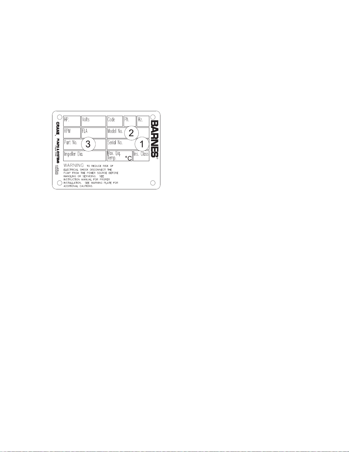
D-3.1) Identifi cation Plate:
Record the numbers from the pump identifi cation plate on
both START-UP REPORT provided at the end of the manual
for future reference.
D-3.2) Insulation Test:
Before the pump is put into service, an insulation (megger)
test should be performed on the motor. The resistance values
(ohms) as well as the voltage (volts) and current (amps)
should be recorded on the start-up report.

8
MODEL
NO
HP VOLT PH/Hz RPM
(Nom)
NEMA
START
CODE
INSUL.
CLASS
FULL
LOAD
AMPS
LOCKED
ROTOR
AMPS
CORD
SIZE
CODE
TYPE
CORD
O.D.
± .02 (.5)
in (mm)
WINDING
RESISTANCE
MAIN -- START
2SEV1522L 1.5 240 1 / 60 3450 A F 13.5 31.5 12/3 SOW 0.61 (15.5) 2.15 -- 12.49
2SEV1592L 1.5 200/240 3 / 60 3450 C F 10.8/9.8 27.0 14/4 SOW 0.60 (15.2) 4.22
2SEV1542L 1.5 480 3 / 60 3450 F F 4.9 13.5 14/4 SOW 0.60 (15.2) 17.0
2SEV1552L 1.5 600 3 / 60 3450 F B 3.9 11.0 14/4 SOW 0.60 (15.2) 22.2
2SEV2022L 2.0 240 1 / 60 3450 C F 16.0 42.0 12/3 SOW 0.61 (15.5) 1.26 -- 55.34
2SEV2092L 2.0 200/240 3 / 60 3450 J F 13.2/12 30.0 14/4 SOW 0.60 (15.2) 3.08
2SEV2042L 2.0 480 3 / 60 3450 J F 6.0 15.0 14/4 SOW 0.60 (15.2) 12.30
2SEV2052L 2.0 600 3 / 60 3450 J B 4.8 12.0 14/4 SOW 0.60 (15.2) 19.70
2SEV1522DS 1.5 240 1 / 60 3450 A F 13.5 31.5 12/3 SOW 0.61 (15.5) 2.15 -- 12.49
2SEV1592DS 1.5 200/240 3 / 60 3450 C F 10.8/9.8 27.0 14/4 SOW 0.60 (15.2) 4.22
2SEV1542DS 1.5 480 3 / 60 3450 F F 4.9 13.5 14/4 SOW 0.60 (15.2) 17.0
2SEV1552DS 1.5 600 3 / 60 3450 F B 3.9 11.0 14/4 SOW 0.60 (15.2) 22.2
2SEV2022DS 2.0 240 1 / 60 3450 C F 16.0 42.0 12/3 SOW 0.61 (15.5) 1.26 -- 55.34
2SEV2092DS 2.0 200/240 3 / 60 3450 J F 13.2/12 30.0 14/4 SOW 0.60 (15.2) 3.08
2SEV2042DS 2.0 480 3 / 60 3450 J F 6.0 15.0 14/4 SOW 0.60 (15.2) 12.30
2SEV2052DS 2.0 600 3 / 60 3450 J B 4.8 12.0 14/4 SOW 0.60 (15.2) 19.70
3SEV1522L 1.5 240 1 / 60 3450 A B 13.5 31.5 12/3 SOW 0.61 (15.5) 2.15 -- 12.49
3SEV1592L 1.5 200/240 3 / 60 3450 C B 10.8/9.8 27.0 14/4 SOW 0.60 (15.2) 4.22
3SEV1542L 1.5 480 3 / 60 3450 F B 4.9 13.5 14/4 SOW 0.60 (15.2) 17.0
3SEV1552L 1.5 600 3 / 60 3450 F B 3.9 11.0 14/4 SOW 0.60 (15.2) 22.2
3SEV2022L 2.0 240 1 / 60 3450 C B 16.0 42.0 12/3 SOW 0.61 (15.5) 1.26 -- 55.34
3SEV2092L 2.0 200/240 3 / 60 3450 J B 13.2/12 30.0 14/4 SOW 0.60 (15.2) 3.08
3SEV2042L 2.0 480 3 / 60 3450 J B 6.0 15.0 14/4 SOW 0.60 (15.2) 12.30
3SEV2052L 2.0 600 3 / 60 3450 J B 4.8 12.0 14/4 SOW 0.60 (15.2) 19.70
3SEV1522DS 1.5 240 1 / 60 3450 A B 13.5 31.5 12/3 SOW 0.61 (15.5) 2.15 -- 12.49
3SEV1592DS 1.5 200/240 3 / 60 3450 C B 10.8/9.8 27.0 14/4 SOW 0.60 (15.2) 4.22
3SEV1542DS 1.5 480 3 / 60 3450 F B 4.9 13.5 14/4 SOW 0.60 (15.2) 17.0
3SEV1552DS 1.5 600 3 / 60 3450 F B 3.9 11.0 14/4 SOW 0.60 (15.2) 22.2
3SEV2022DS 2.0 240 1 / 60 3450 C B 16.0 42.0 12/3 SOW 0.61 (15.5) 1.26 -- 55.34
3SEV2092DS 2.0 200/240 3 / 60 3450 J B 13.2/12 30.0 14/4 SOW 0.60 (15.2) 3.08
3SEV2042DS 2.0 480 3 / 60 3450 J B 6.0 15.0 14/4 SOW 0.60 (15.2) 12.30
3SEV2052DS 2.0 600 3 / 60 3450 J B 4.8 12.0 14/4 SOW 0.60 (15.2) 19.70
Winding Resistance ± 5%, measured from terminal block. Pump rated for operation at ± 10% voltage at motor.
Optional - Moisture sensor cord for DS models is 18/5 SOW, 0.47 ± .02 O.D.
Optional - Temperature sensor cord for 3 phase models is 14/3 SOW, 0.53 ± .02 O.D.
Optional - Moisture & Temperature sensor cord for 3 phase DS models is 18/5 SOW, 0.47 ± .02 O.D.
D-3.3) Pump-Down Test:
After the pump has been properly wired and lowered into the
basin, sump or lift station, it is advisable to check the system by
fi lling with liquid and allowing the pump to operate through its
pumping cycle. The time needed to empty the system, or pump-
down time along with the volume of water, should be recorded
on the start-up report.
9
SECTION E: PREVENTATIVE MAINTENANCE
As the motor is oil fi lled, no lubrication or other maintenance
is required, and generally Barnes Pumps will give very
reliable service and can be expected to operate for years on
normal sewage pumping without failing. However as with any
mechanical piece of equipment a preventive maintenance
program is recommended and suggested to include the
following checks:
1) Inspect motor chamber for oil level and contamination
and repair as required per section F-1.
2) Inspect impeller and body for excessive build-up or
clogging and repair as required per section F-2.
3) Inspect motor and bearings and replace as required
per section F-3.
4) Inspect seal for wear or leakage and repair as required
per section F-4.
SECTION F: SERVICE AND REPAIR
NOTE: All item numbers in ( ) refer to Figures 15 thru 18.
F-1) Lubrication:
Anytime the pump is removed from operation, the cooling oil
in the motor housing (6) should be checked visually for oil
level and contamination.
F-1.1) Checking Oil:
Motor Housing- To check oil, set unit upright. Remove pipe
plug (39) from motor housing (6). With a fl ashlight, visually
inspect the oil in the motor housing (6) to make sure it is
clean and clear, light amber in color and free from suspended
particles. Milky white oil indicates the presence of water. Oil
level should be just above the motor when pump is in vertical
position.
F-1.2) Testing Oil:
1.) Place pump on it’s side, remove pipe plug (39), from
motor housing (6) and drain oil into a clean, dry container.
2.) Check oil for contamination using an oil tester with a
range to 30 Kilovolts breakdown.
3.) If oil is found to be clean and uncontaminated
(measuring above 15 KV. breakdown), refi ll the motor
housing as per section F-1.4.
4.) If oil is found to be dirty or contaminated (or measures
below 15 KV. breakdown), the pump must be
carefully inspected for leaks at the shaft seal (28), cord
assemblies (16) and (56 if used), square ring (27) and
pipe plug (39), before refi lling with oil. To locate the
leak, perform a pressure test as per section F-1.3.
After leak is repaired, dispose of old oil properly, and
refi ll with new oil as per section F-1.4.
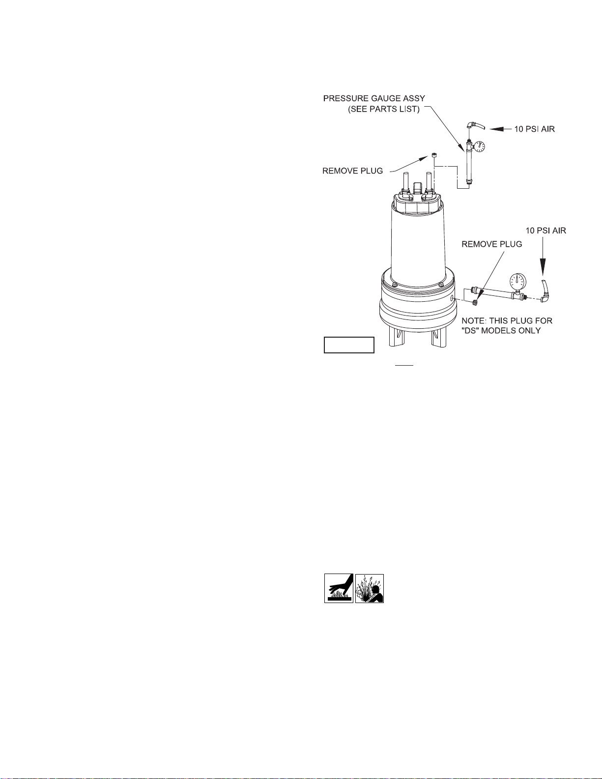
F-1.3) Pressure Test:
Pumps that have been disassembled, Motor Housing - If
the pump has been disassembled, the oil should be drained
before a pressure test, as described in section F-1.1. Remove
pipe plug (39) from motor housing (6). Apply pipe sealant to
pressure gauge assembly and tighten into hole (See Figure
2). Pressurize motor housing to 10 P.S.I. Use soap solution
around the sealed areas and inspect joints for “air bubbles”.
If, after fi ve minutes, the pressure is still holding constant,
and no “bubbles” are observed, slowly bleed the pressure
and remove the gauge assembly. Replace oil as described in
section F-1.4. If the pressure does not hold, then the leak must
be located and repaired.
Pumps that have NOT been disassembled, Motor Housing-
The pressure test may be done with the oil at its normal level.
Remove pipe plug (39) from motor housing (6). Apply pipe
sealant to pressure gauge assembly and tighten into hole
(See Figure 2). Pressurize motor housing to 10 P.S.I. Use
soap solution around the sealed areas above the oil level and
inspect joints for “air bubbles”. For sealed areas below the oil
level, leaks will seep oil. If, after fi ve minutes, the pressure
is still holding constant, and no “bubbles”/oil seepage is
observed, slowly bleed the pressure and remove the gauge
assembly. If the pressure does not hold, then the leak must be
located and repaired.
Seal Chamber (DS Units Only)- Set unit on its side with
fi ll plug (44) downward, remove plug (44) and drain all oil
from seal chamber. Apply pipe sealant to pressure gauge
assembly and tighten into hole in outer seal plate (29).
Pressurize seal chamber to 10 P.S.I. and check for leaks as
outlined above.
CAUTION ! Pressure builds up extremely
fast, increase pressure by “tapping” air
nozzle. Too much pressure will damage
seal. DO NOT exceed 10 P.S.I.
F-1.4) Replacing Oil:
Motor Housing- Set unit upright and refi ll with new cooling
oil as per Table 1 (see parts list for amount). Fill to just above
motor as an air space must remain in the top of the motor
housing to compensate for oil expansion (see Fig. 15 or 17).
Apply pipe thread compound to threads of pipe plug (39) then
assemble to motor housing (6).
FIGURE 2
10
Important ! - For single phase units, oil level
should be below capacitor
Seal Chamber (DS Units Only)- Set unit on its side, with
plug (44) upward, and refi ll with new oil as per Table 1 (see
parts list for amount). Apply pipe thread compound to threads
of pipe plug (44) and assemble to outer seal plate (29).
Warning ! - Do not overfi ll oil. Overfi lling of
motor housing with oil can create excessive
and dangerous hydraulic pressure which
can destroy the pump and create a hazard.
Overfi lling oil voids warranty.
TABLE 1 - COOLING OIL - Dielectric
SUPPLIER GRADE
BP Enerpar SE100
Conoco Pale Paraffi n 22
Mobile D.T.E. Oil Light
G & G Oil Circulating 22
Imperial Oil Voltesso-35
Shell Canada Transformer-10
Texaco Diala-Oil-AX
Woco Premium 100
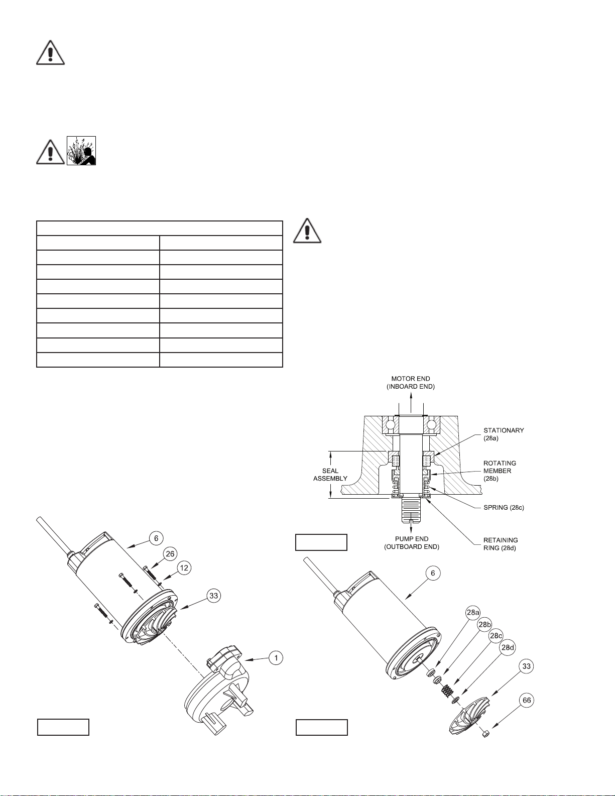
F-2) Impeller and Volute Service:
F-2.1) Disassembly and Inspection:
To clean out volute (1) or replace impeller (33), disconnect
power, remove hex bolts (26), and lockwasher (12), vertically
lift motor and seal plate assembly from volute (1) and spacer
ring (31), see Figure 3. Clean out body if necessary. Clean
and examine impeller (33), for pitting or wear and replace if
required, inspect gasket (36) and replace if cut or damaged.
If the impeller (33) needs replacing, place a fl at screwdriver in
the slot of the end of the shaft to hold the shaft stationary while
unscrewing the jam nut (66) and impeller (33).
F-2.2) Reassembly:
To install impeller (33), clean the threads with thread locking
compound cleaner. Apply removable Loctite® 603 or equivalent
to shaft threads. Screw impeller onto the shaft hand tight while
using a screwdriver in the slot at the end of the shaft to hold it
stationary. Apply thread locking compound (57) to shaft threads
then install jam nut (66) and torque to 40 ft. lbs. It is important
that the spring of the lower shaft seal (28) seats in the hub of
the impeller (33). Rotate impeller to check for binding. Position
gasket (36) on volute fl ange and place spacer ring (31) over it.
Place another gasket (36) on spacer ring and position impeller
and motor housing on spacer ring (31). Position lockwasher
(12) on cap screw (26) and screw into volute (1). Torque to 100
in-lbs. Check for free rotation of motor and impeller.
F-3) Shaft Seal Service:
Important ! - Handle seal parts with extreme care.
DO NOT scratch or mar lapped surfaces.
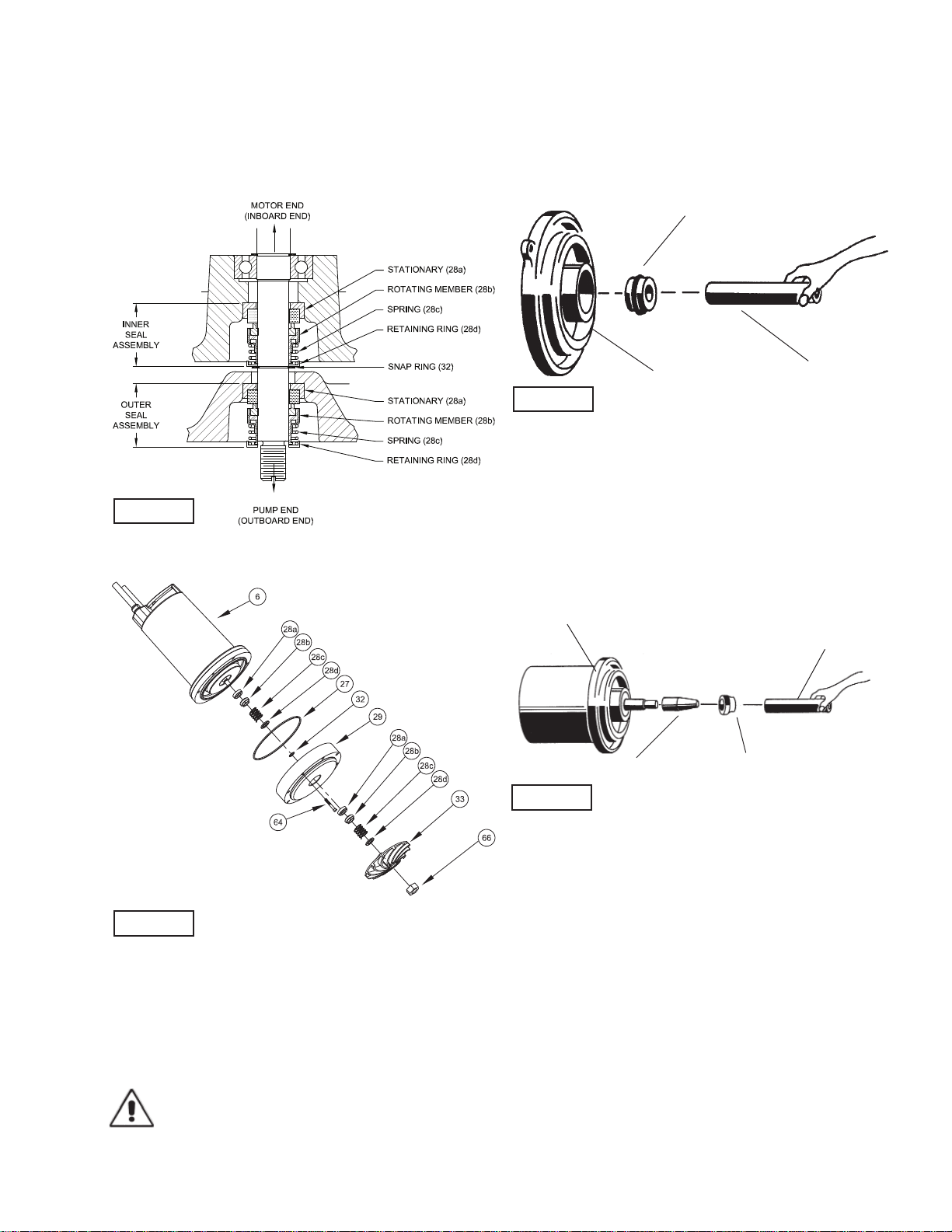
F-3.1) Disassembly and Inspection:
Outer Seal (All Units)- To expose shaft seal (28) for
examination, disassemble volute and impeller as outlined in
paragraph F-2.1. If further repair is required, remove retaining
ring (28d), spring (28c) and rotating member (28b) from shaft
(see Figures 4 & 5). Examine all seal parts and especially
contact faces. Inspect seal for signs of wear such as uneven
wear pattern on stationary members, chips and scratches
on either seal face. DO NOT interchange seal components,
replace the entire shaft seal (28). If replacing seal, remove
stationary (28a) by prying out with fl at screwdriver.
FIGURE 3
FIGURE 5
FIGURE 4
11
FIGURE 8
Inner Seal (DS Units Only)- To expose inner shaft seal
(28) for examination, remove outer seal as outlined above.
Remove socket head cap screws (64). Lift outer seal plate (29)
and square-ring (27) from inner seal plate (5), See Figures 6 &
7. If further repair is required, remove snap ring (32), retaining
ring (28d), spring (28c) and rotating member (28b) from shaft.
Examine as outlined in outer seal paragraph. If replacing seal,
remove stationary (28a) by prying out with fl at screwdriver.
F-3.2) Reassembly:
Inner Seal (DS Units Only)- Clean and oil seal cavities in seal
plates (5, 29). Lightly oil (DO NOT use grease) outer surface
of stationary member (28a). Press stationary member (28a)
fi rmly into inner seal plate (5), using a seal pusher (see parts
list - seal tool kit). Nothing but the seal pusher is to come in
contact with seal face (see Figure 8).
Important ! - DO NOT hammer on the seal pusher-
it will damage the seal face.
Make sure the stationary member is in straight. Slide a bullet
(see parts list - seal tool kit) over motor shaft. Lightly oil (DO NOT
use grease) shaft, bullet and inner surface of bellows on rotating
member (28b), see Figure 9. With lapped surface of rotating
member (28b) facing inward toward stationary member, slide
rotating member over bullet and onto shaft, using seal pusher,
until lapped faces of (28a) and (28b) are together (see Figure 8).
It is extremely important to keep seal faces clean during
assembly. Dirt particles lodged between these faces will cause
the seal to leak. Place spring (28c) over shaft and in place on
rotating member (28b), making sure it is seated on retainer and
not cocked or resting on bellows tail. Slide retaining ring (28d)
over shaft and let rest on spring (28c). Replace snap ring (32)
in groove of shaft. Set square-ring (27) in groove on outer seal
plate (29) and place outer seal plate (29) onto inner seal plate
(5). Replace socket head cap screws (64) and torque to 60 in-lbs.
Outer Seal (All Units) - Press stationary member (28a) fi rmly
into outer seal plate (5, or 29 on DS Units) as described
above. Slide rotating member (28b) onto stationary member
using seal pusher as described above. Place spring (28c) and
retaining ring (28d) onto rotating member (28b). Assemble
impeller and volute as outlined in paragraph F-2.2. Replace oil
as outlined in paragraph F-1.4.
F-4) Motor and Bearing Service:
F-4.1) Disassembly and Inspection:
To examine or replace the motor (7), capacitor (9, single
phase units), controls (56, optional), and bearing (25), drain
oil from motor as outlined in paragraph F-1.1. Disassemble
volute and impeller as outlined in paragraph F-2.1 and
disassemble shaft seal as outlined in paragraph F-3.1.
FIGURE 7
FIGURE 6
Rotating Member
(28B)
Motor & Seal Plate
Bullet
Seal Pusher
FIGURE 9
Seal Pusher
Seal Plate (5) for L series
and (29) for DS series
Stationary Member
(28A) Polished Face Out
12
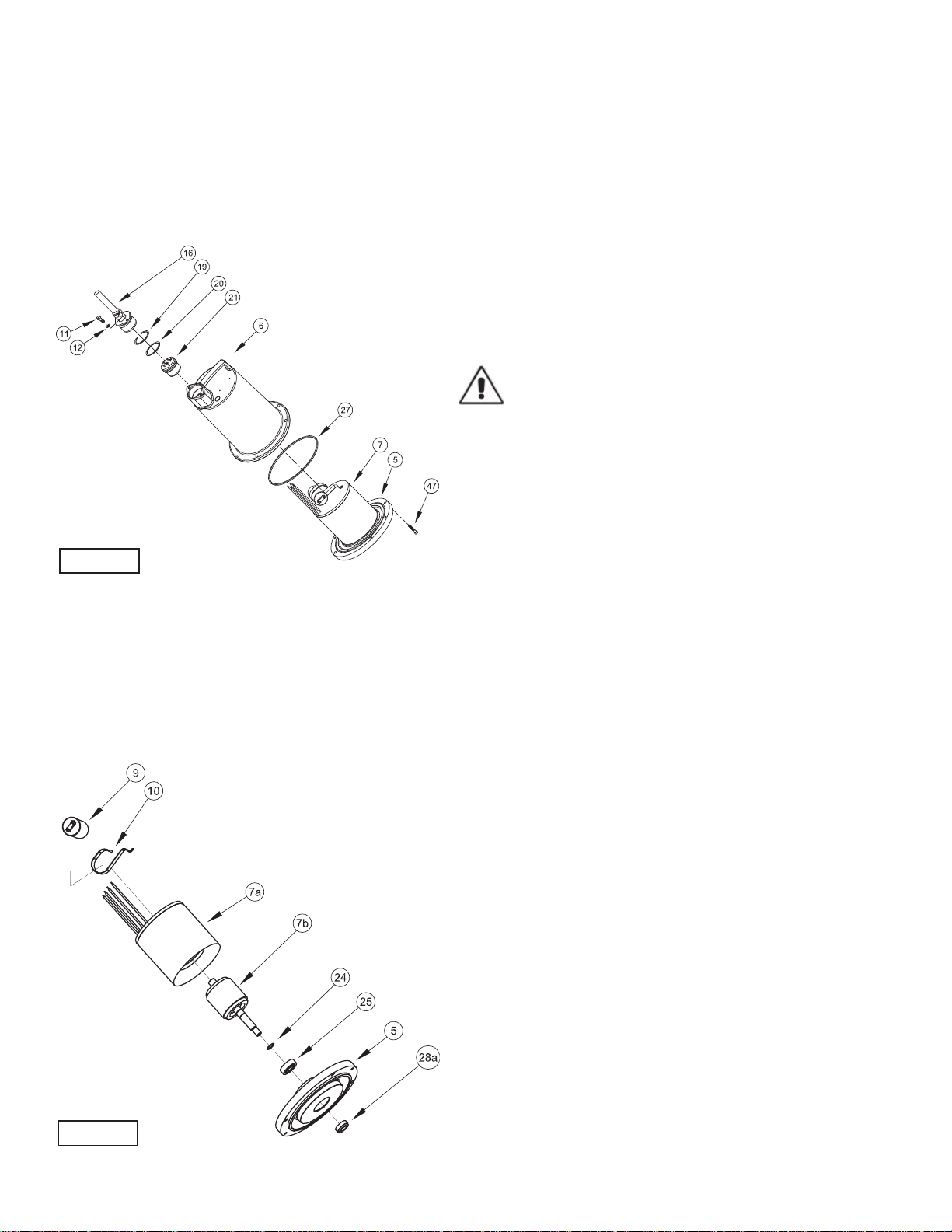
Position unit upright, using blocks to avoid resting unit on
shaft. Unscrew cord hex bolts (11) and remove compression
fl ange (16a) and power cord (16). Remove snap ring (19) with
a fl at head screwdriver. Pull the terminal block (21) out of the
housing (6) using a T-bolt or a pair of pliers and a .25-20 screw
in the threads of the terminal block (21). Be sure to leave slack
on the motor leads connected underneath. Use needle nose
pliers to pull each female connector off of the pins on the
underside of the terminal block (21), see Figure 10. The unit
voltage should be noted.
Repeat cord and terminal block removal procedure for any
control cords (56) if equipped. Remove socket head screws
(47). Vertically lift the motor housing (6) from seal plate (5)
by lifting handle (13). Inspect square ring (27) for damage or
cuts. Remove the motor bolts and lift motor stator from seal
plate (5). Disconnect capacitor leads from capacitor (9, single
phase units). Examine bearing (25) and replace if required. If
replacement is required, remove bearing (25) from motor shaft
using a wheel puller or arbor press, see Figure 11
Check motor capacitor (9, single phase units) with an Ohm
meter by fi rst grounding the capacitor by placing a screwdriver
across both terminals and then removing screwdriver. Connect
Ohm meter (set on high scale) to terminals. If needle moves
to infi nity (∞) then drifts back, the capacitor is good. If needle
does not move or moves to infi nity (∞) and does not drift back,
replace capacitor (9).
If moisture sensors (4, optional) are damaged, disconnect
leads by removing machine screws (45) and washers (46)
from probes (4). Remove probes (4) from seal plate (5). To
test the temperature sensor (50, optional), check for continuity
between the black and white wires. If found to be defective,
contact a motor service station or Barnes Pumps Service
department. Inspect motor winding for shorts and check
resistance values. Check rotor for wear. If rotor or the stator
windings are defective, the complete motor must be replaced.
Important ! - All parts must be clean before
reassembly.
F-4.2) Reassembly:
Moisture Sensors, DS Models - If pump is equipped with
optional moisture sensors, reassemble by applying thread
compound to threads on probes (4) and install in upper seal
plate (5), see Figures 17 and 18. Connect wire assemblies
(53) to probes (4) with washers (46) and machine screws (45).
Thermal Sensors- If pump is equipped with optional thermal
sensors use terminal connectors (52) to connect wire
assemblies (51) to sensor leads. If found to be defective, contact
a motor service station or Barnes Pumps Service department.
Bearings- When replacing bearing, be careful not to damage
the rotor or shaft threads. Clean the shaft thoroughly. Press
bearing (25) on the motor shaft, position squarely onto the
shaft applying force to the inner race of the bearing only, until
bearing seats against the retaining ring (24).
Motor- Slide lower bearing (25) and motor shaft squarely into
the seal plate (5) until bearing seats on the bottom. Place
stator over rotor, lining up motor bolts with holes in seal plate
(5). Position capacitor (9, single phase units) so that it will lay
on the opposite side of the cord entry bosses of the motor
housing (6). Reconnect capacitor leads. Torque motor tie bolts
to 17 in-lbs. Set square ring (27) in groove on seal plate (5).
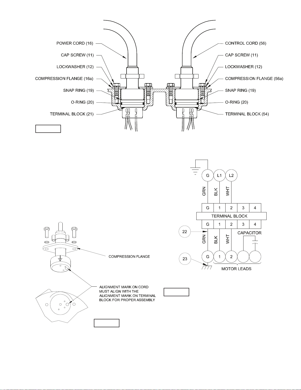
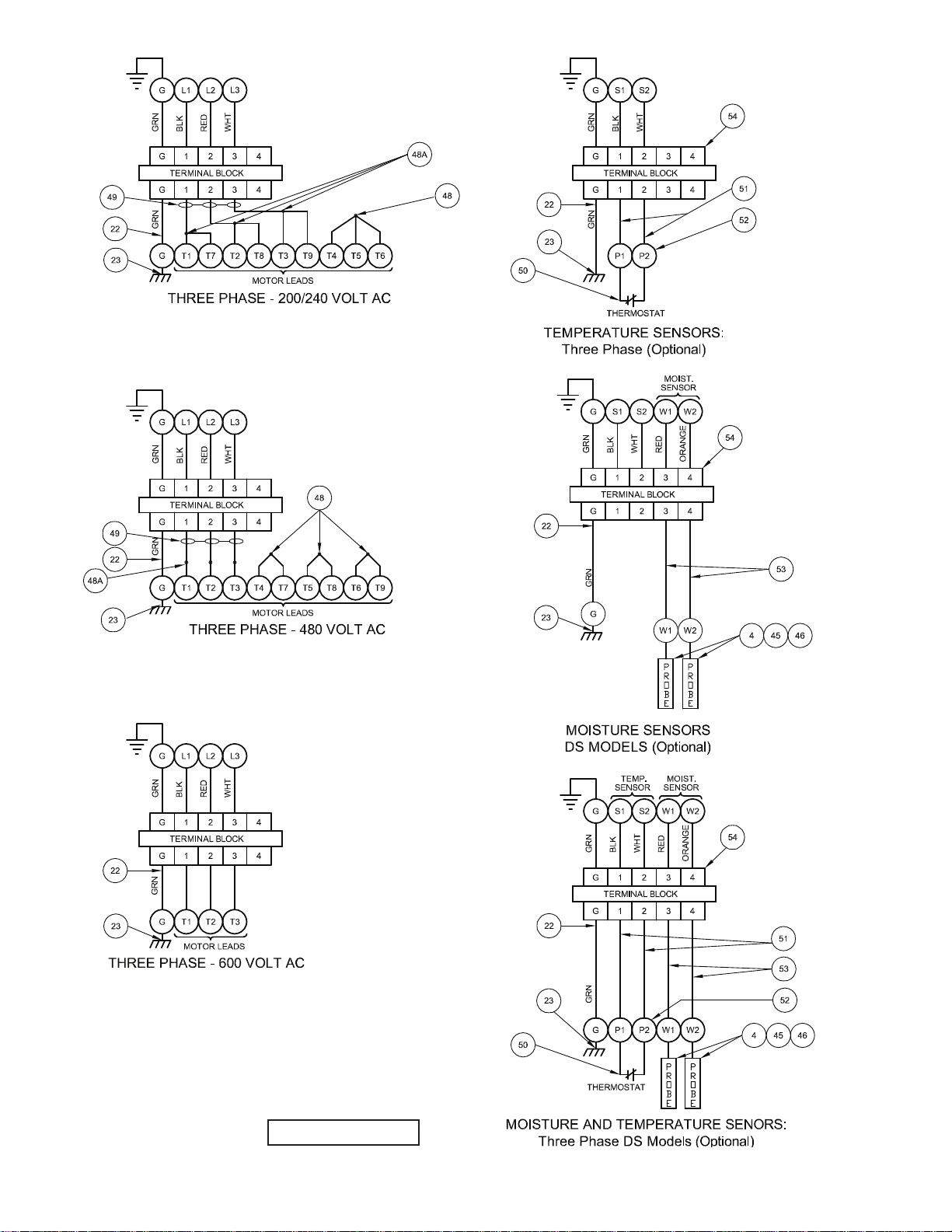
F-4.3) Wiring Connections:
Check power cords (16) and control cord (56, if used), for
cracks or damage and replace if required (see Figure 12).
Make internal wiring connections which are independent of
the terminal block as shown, using connectors (48) and wire
assemblies (49) as required. Do not use wire nuts. Slip motor
leads and ground wire into fi berglass sleeve. Lower motor
housing (6) down onto seal plate (5) while aligning holes and
stringing motor leads through the cord entry bore(s). (Slipping
cords inside a 1 ft. length of .5” conduit makes this easier).
Place socket head cap screws (47) through seal plate (5) into
motor housing (6) and torque to 60 in-lbs. Reconnect motor and
optional control leads to the underside of the terminal block(s)
(21), (54 optional) as shown in Figure 14. Note that the pins
are numbered underneath the terminal block. Place o-ring (20)
into groove in terminal block and lubricate with dielectric oil.
Press the terminal block (21) into the housing so it seats
FIGURE 10
FIGURE 11
13
FIGURE 13
completely below the snap ring groove. Place snap ring
(19) into groove in cord entry bore of housing. Repeat
terminal block installation for control cord, if equipped.
F-4.4) Cord Assemblies:
Power/Control Cord - Refi ll the cooling oil as outlined in
paragraph F-1.3. Make wire connections as outlined in
paragraph F-4.3. Insert female end of cord plug into housing
bore aligning timing mark with hole in terminal block (21), see
Figure 13. Compress cord plug with compression fl ange (16a)
by tightening hex bolts (11) into the housing (6). Torque to 132
in-lbs.
FIGURE 12
FIGURE 14
SINGLE PHASE - 240 VOLT AC (PSC)
14
FIGURE 14 - CONTIUED
15
SECTION: G REPLACEMENT PARTS
G-1 ORDERING REPLACEMENT PARTS:
When ordering replacement parts, ALWAYS furnish the
following information:
1. Pump serial number and date code. (Paragraph G-4)
2. Pump model number. (Paragraph G-3)
3. Pump part number. (Paragraph G-2)
4. Part description.
5. Item part number.
6. Quantity required.
7. Shipping instructions.
8. Billing Instructions.
G-2 PART NUMBER:
The part number consists of a six (6) digit number, which
appears in the catalog. A one or two letter suffi x may follow this
number to designate the design confi guration. This number is
used for ordering and obtaining information.
G-3 MODEL NUMBER:
This designation consists of numbers and letters which
represent the discharge size, series, horsepower, motor phase
and voltage, speed and pump design. This number is used for
ordering and obtaining information.
G-4 SERIAL NUMBER:
The serial number block will consist of a six digit number,
which is specifi c to each pump and may be preceded by
a alpha character, which indicates the plant location. This
number will also be suffi xed with a four digit number, which
indicates the date the unit was built (Date Code).
EXAMPLE: A012345 0490.
Reference the six digit portion (Serial Number) of this number
when referring to the product.

16
TROUBLE SHOOTING
CAUTION ! Always disconnect the pump from the electrical power source before handling.
If the system fails to operate properly, carefully read instructions and perform maintenance recommendations.
If operating problems persist, the following chart may be of assistance in identifying and correcting them:
MATCH “CAUSE” NUMBER WITH CORRELATING “CORRECTION” NUMBER.
NOTE: Not all problems and corrections will apply to each pump model.
PROBLEM CAUSE CORRECTION
Pump will not run 1. Poor electrical connection, blown fuse,
tripped breaker or other interruption of power,
improper power supply.
2. Motor or switch inoperative (to isolate
cause, go to manual operation of pump).
2a. Flaot movement restricted.
2b. Switch will not activate pump or is defec-
tive.
3. Insuffi cient liquid level.
1. Check all electrical connections for
security. Have electrician measure current
in motor leads, if current is within ±20%
of locked rotor Amps, impeller is probably
locked. If current is 0, overload may be
tripped. Remove power, allow pump to cool,
then recheck current.
2a. Reposition pump or clean basin as
required to provide adequate clearance for
fl oat.
2b. Disconnect level control. Set ohmmeter
for a low range, such as 100 ohms full scale
and connect to level control leads. Actuate
level control manually and check to see that
ohmmeter shows zero ohms for closed switch
and full scale for open switch. (Float Switch).
3. Make sure liquid level is at least equal to
suggested turn-on point.
4. Recheck all sizing calculations to
determine proper pump size.
5. Check discharge line for restrictions,
including ice if line passes through or into
cold areas.
6. Remove and examine check valve for
proper installation and freedom of operation.
7. Open valve.
8. Check cutter for freedom of operation,
security and condition. Clean cutter and inlet
of any obstruction.
9. Loosen union slightly to allow trapped air
to escape.Verify that turn-off level of switch
is set so that the suction is always fl ooded.
Clean vent hole.
10. Remove & examine for damage. Replace
pump stator if required.
11. Repair fi xtures as required to eliminate
leakage.
12. Check pump temperature limits & fl uid
temperature.
13. Replace portion of discharge pipe with
fl exible connector.
14. Turn to automatic position.
15. Check for leaks around basin inlet and
outlets.
Pump will not turn off 2a. Float movement restricted.
2b. Switch will not activate pump or is defec-
tive.
4. Excessive infl ow or pump not properly sized
for application.
9. Pump may be airlocked.
14. H-O-A switch on panel is in “HAND” posi-
tion
Pump hums but does not run 1. Incorrect voltage
8. Cutter jammed or loose on shaft, worn or
damaged, inlet plugged.
Pump delivers insuffi cient capacity 1. Incorrect voltage.
4. Excessive infl ow or pump not properly sized
for application.
5. Discharge restricted.
6. Check valve stuck closed or installed
backwards.
7. Shut-off valve closed.
8. Cutter jammed or loose on shaft, worn or
damaged, inlet plugged.
9. Pump may be airlocked.
10. Pump stator damaged/torn.
Pump cycles too frequently or runs
periodically when fi xtures are not in use
6. Check valve stuck closed or installed
backwards.
11. Fixtures are leaking.
15. Ground water entering basin.
Pump shuts off and turns on indepen-
dent of switch, (trips thermal overload
protector). CAUTION! Pump may start
unexpectedly. Disconnect power supply.
1. Incorrect voltage.
4. Excessive infl ow or pump not properly sized
for application.
8. Cutter jammed, loose on shaft, worn or
damaged, inlet plugged.
12. Excessive water temperature.
Pump operates noisily or vibrates
excessively
4. Operating at too high a pressure.
5. Discharge restricted.
8. Cutter broken.
13. Piping attachments to buiding structure too
rigid or too loose.
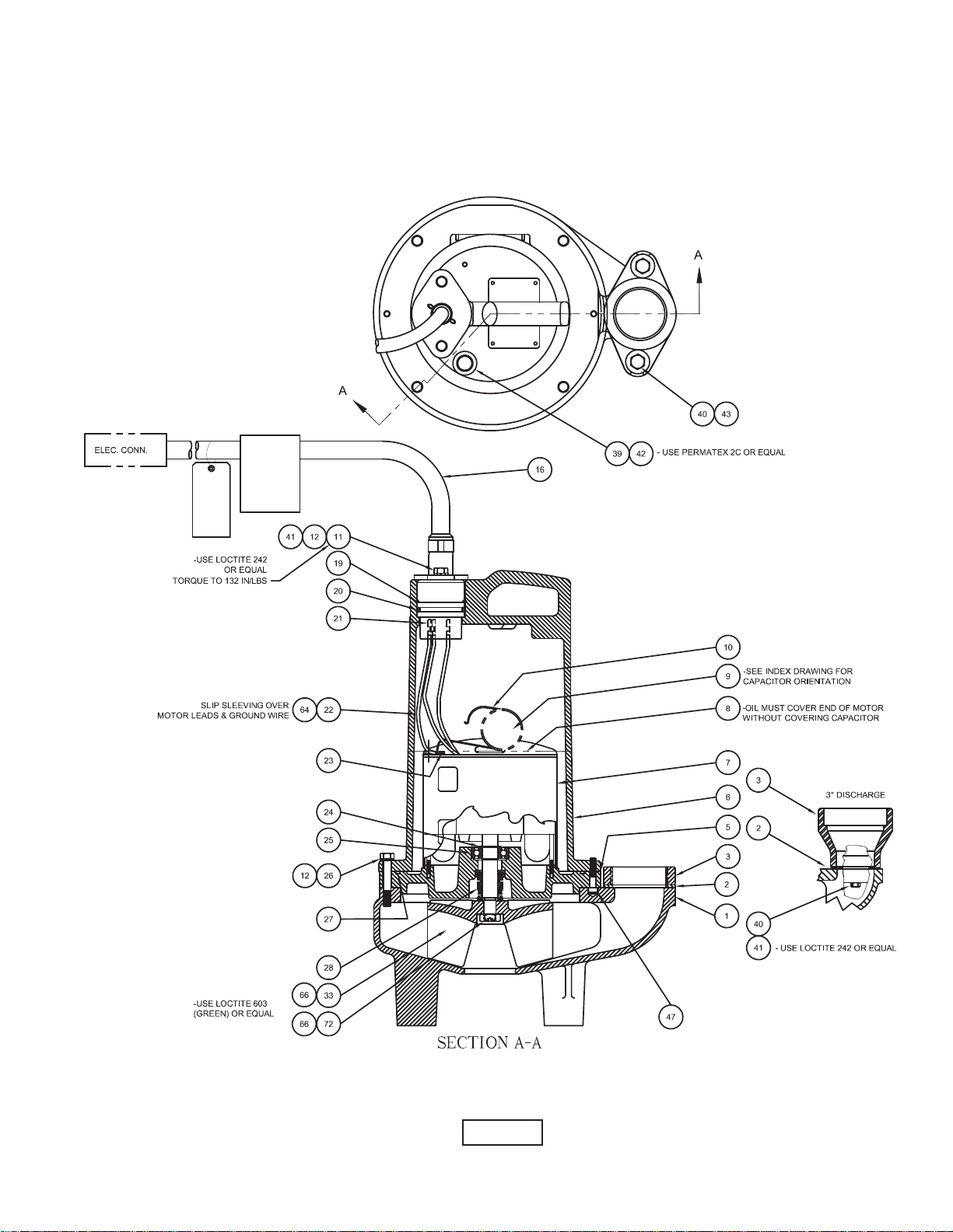
17
FIGURE 15
2SEV- L & 3SEV- L Series, Single Seal
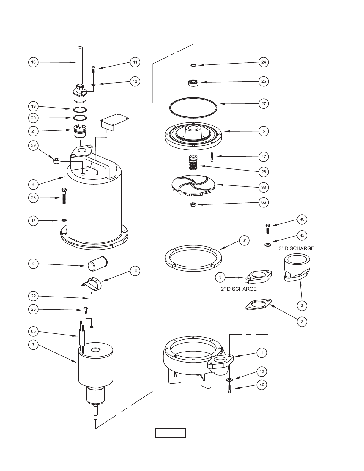
18
FIGURE 16
2SEV- L & 3SEV- L Series, Single Seal
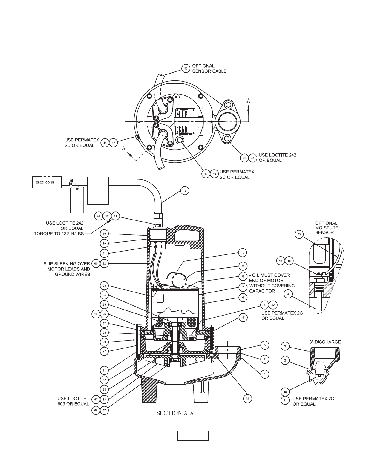
19
FIGURE 17
2SEV- DS & 3SEV- DS Series, Double Seal
20
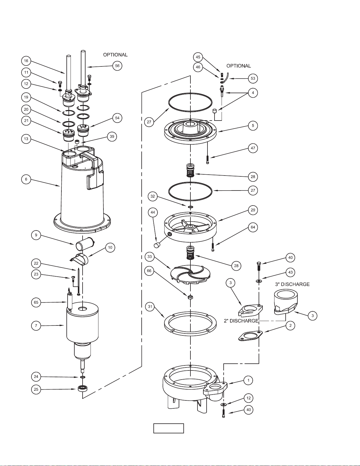
FIGURE 18
2SEV- DS & 3SEV- DS Series, Double Seal

21
PARTS KITS
Seal Repair Kits:
Single Seal.........P/N - 130181 (+) 2, 20, 27, 28, 36
Double Seal........P/N - 130177 (†) 2, 20, 27, 28, 36
Service Kits
Single Seal.........P/N - 130208 (◊) 2, 20, 22, 24, 25, 27, 28, 36, 44, 49, 65, 66
Double Seal........P/N - 130173 (♦) 2, 20, 22, 24, 25, 27, 28, 32, 36, 44, 49, 65, 66
Pressure Gauge Kit .. ......P/N - 085343
PARTS LIST
ITEM QTY. PART NO. DESCRIPTION
1 1 055400 Volute
2 1 069140 +†◊♦ Gasket
3 1 026210 Flange, 2” Discharge
105153 Flange, 3” Discharge
4 2 003217 Pipe Plug All double seal (Std), .25” NPT, ZP
2 039383 Moisture Sensor Probes (Optional) for moisture sensor
5 1 084343 Seal Plate All single seal
084429 All double seal
6 1 108342A Motor Housing (Std)
110328B (Optional) for moisture and temp. sensors
7 1 Motor:
115927D 2SEV1522DS, 2SEV2022DS, 3SEV1522DS, 3SEV2022DS
115928D 2SEV1592DS, 2SEV2092DS, 3SEV1592DS, 3SEV2092DS
115928D 2SEV1542DS, 2SEV2042DS, 3SEV1542DS, 3SEV2042DS
115929D 2SEV1552DS, 2SEV2052DS, 3SEV1552DS, 3SEV2052DS
115927S 2SEV1522L, 2SEV2022L, 3SEV1522L, 3SEV2022L
115928S 2SEV1592L, 2SEV2092L, 3SEV1592L, 3SEV2092L
115928S 2SEV1542L, 2SEV2042L, 3SEV1542L, 3SEV2042L
115929S 2SEV1552L, 2SEV2052L, 3SEV1552L, 3SEV2052L
8 96oz 029034 Oil All single seal
120oz 029034 Oil All double seal (Includes 24oz. in Seal Chamber)
9 1 036391 Capacitor 1 Phase,
10 1 039858 Capacitor Bracket 1 Phase
11 2 1-129-1 Hex. Hd. Cap Screw (Std), 5/16-18 x .75” Lg., Stainless
4 1-129-1 Hex. Hd. Cap Screw (Optional) for moisture and temp. sensors
12 6 026322 Lockwasher (Std), 5/16, Stainless
8 026322 Lockwasher (Optional) for moisture and temp. sensors
16 1 See Table 2 Power Cord Set
19 1 105197 ◊ Snap Ring (Std)
2 105197 ♦ Snap Ring (Optional) for moisture and temp. sensors
20 1 2-31051-224 +◊ O-ring (Std)
2 2-31051-224 †♦ O-ring (Optional) for moisture and temp. sensors
21 1 103760 Terminal Block 1 Phase
103583 3 Phase
22 1 105111 ◊♦ Ground Wire Assembly 3 Phase
1 105111A ◊♦ Ground Wire Assembly 1 Phase
2 105111 Ground Wire Assembly (Optional) for moisture and temp. sensors
23 1 016660 Screw, Self Tapping #8-32 x .375” Lg., Stainless
24 1 061143 ◊♦ Retaining Ring
25 1 039734 ◊♦ Bearing
26 4 1-158-1 Cap Screw All single seal, 5/16-18 x 2.50” Lg., Stainless
0116491 All double seal
27 1 027269 +◊ Square Ring All single seal
2 027269 †♦ Square Ring All double seal
28 1 Shaft Seal: (Qty 2 for DS)
067562 +†◊♦ Carbon/Ceramic/Buna-N (STD)
067562SB Tungsten/Tungsten/Buna-N
067562SD Silicon Carbide/Silicon Carbide/Buna-N
067562SF Carbon/Ceramic/Viton
067562SH Tungsten/Tungsten/Viton
067562SK Silicon Carbide/Silicon Carbide/Viton
067562SM Silicon Carbide/Tungsten/Buna-N
067562SN Carbon/Ni-Resistant/Buna-N
067562SP Carbon/Ni-Resistant/Neoprene

22
29 1 115943 Seal Housing All double seal
31 1 105145 Spacer Ring
32 1 2-27008-62 ♦ Retaining Ring All double seal
33 1 Impeller, Cast Iron
107032CTE 4.62 Dia. (STD for a 2.0 HP)
107032CTF 4.50 Dia.
107032CTG 4.37 Dia. (STD for a 1.5 HP)
107032CTH 4.25 Dia.
107032CTJ 4.12 Dia.
107032CTK 4.00 Dia.
107032CTL 3.88 Dia.
39 1 014270 Pipe Plug .375” NPT, ZP
40 2 1-36-1 Hex. Hd. Cap Screw 2” Discharge, 3/8-16 x 1.25” Lg., Stainless
2-23030-59 Soc. Hd. Cap Screw 3” Discharge, 5/16-18 x 1.50” Lg., Stainless
41 A/R --------- Loctite 242
42 A/R --------- Permatex 2C
43 2 082727 Washer 2” Discharge, 3/8” Stainless
44 1 003217
♦ Pipe Plug All double seal, .25” NPT, ZP
45 2 5-32-6 Screw (Optional) for moisture sensor, #6-32 x .25” Lg., ZP
46 2 052563 Lockwasher (Optional) for moisture sensor #6 Stl.
47 2 084948 Socket Head Screw 1/4-20 x 1.25” Lg., Stainless
48 1 105150 Terminal Connector 200-240V, 3Ph
3 625-00163 Terminal Connector 480V, 3PH
48A 3 085078 Blue-Butt Connector 480V, 3PH
49 3 105149 ◊♦ Wire Assembly 200-240V, 3Ph
50 1 051621 Thermal Sensor (Optional) for temperature sensor, (Not Shown)
51 2 105155 Wire Assembly (Optional) for temperature sensor, (Not Shown)
52 2 134013 Terminal Connector (Optional) for temperature sensor, (Not Shown)
53 2 105106 Wire Assembly (Optional) for moisture sensor
54 1 103584 Terminal Block Temperature sensor options
103585 Moisture and temp. sensor options
56 1 See Table 2 Control Cord (Optional) for moisture and/or temp. sensors
56a 1 103582 Compression Flange Included with Cord Set
57 A/R Loctite 603
64 2 030337 Socket Head Cap Screw Double seal Only, 1/4-20 x 2” Lg., Stainless
65 1 625-02117 ◊♦ Sleeve, Fiberglass
66 1 038132 ◊♦ Jam Nut 5/8-18, SS
TABLE 2 - POWER & SENSOR CORD SETS
CABLE
LENGTH
ITEM #16
240 VOLT
1 PHASE
ITEM #16
3 PHASE
ITEM #56
(OPTIONAL)
Temperature - 3 Phase
ITEM #56
(OPTIONAL)
Moisture and Temperature Sensor
3 Phase or Moisture Sensor
8 FT ---- 103742A 103741A 113288A
15 FT 109498 103742 103741 113288
20 FT 109498XA 103742XA 103741XA 113288XA
30 FT (Std) 109498XC 103742XC 103741XC 113288XC
50 FT 109498XF 103742XF 103741XF 113288XF
75 FT 109498XJ 103742XJ 103741XJ 113288XJ
100 FT 109498XL 103742XL 103741XL 113288XL

23
$&UDQH&R&RPSDQ\
/LPLWHG0RQWK:DUUDQW\
&UDQH3XPSV6\VWHPVZDUUDQWVWKDWSURGXFWVRIRXUPDQXIDFWXUHZLOOEHIUHHRIGHIHFWVLQPDWHULDODQGZRUNPDQVKLS
XQGHU QRUPDO XVH DQG VHUYLFH IRU WZHQW\IRXU PRQWKV DIWHU PDQXIDFWXUH GDWH ZKHQ LQVWDOOHG DQG PDLQWDLQHG
LQDFFRUGDQFHZLWKRXULQVWUXFWLRQV7KLVZDUUDQW\JLYHV\RXVSHFL¿FOHJDOULJKWVDQGWKHUHPD\DOVREHRWKHUULJKWV
ZKLFKYDU\IURPVWDWHWRVWDWH,QWKHHYHQWWKHSURGXFWLVFRYHUHGE\WKH)HGHUDO&RQVXPHU3URGXFW:DUUDQWLHV/DZ
WKH GXUDWLRQ RI DQ\ LPSOLHG ZDUUDQWLHV DVVRFLDWHG ZLWK WKH SURGXFW E\ YLUWXH RI VDLG ODZ LV OLPLWHG WR WKH VDPH
GXUDWLRQDV VWDWHG KHUHLQ WKLV ZDUUDQW\LV D /,0,7(':$55$17<DQG QRFODLPVRI DQ\QDWXUHZKDWVRHYHU
VKDOOEHPDGHDJDLQVWXVXQWLOWKHXOWLPDWHFRQVXPHUKLVVXFFHVVRURUDVVLJQVQRWL¿HVXVLQZULWLQJRIWKHGHIHFW
DQGGHOLYHUVWKHSURGXFWDQGRUGHIHFWLYHSDUWVIUHLJKWSUHSDLGWRRXUIDFWRU\RUQHDUHVWDXWKRUL]HGVHUYLFHVWDWLRQ
6RPHVWDWHV GRQRW DOORZOLPLWDWLRQV RQ KRZ ORQJ DQLPSOLHG ZDUUDQW\ODVWV VRWKH DERYHOLPLWDWLRQ PD\QRW DSSO\
7+(62/($1'(;&/86,9(5(0('<)25%5($&+2)$1<$1'$//:$55$17,(6:,7+5(63(&772$1<
352'8&7 6+$// %( 72 5(3/$&( 25 5(3$,5 $7 285 (/(&7,21 )2% 32,17 2) 0$18)$&785( 25
$87+25,=('5(3$,567$7,2168&+352'8&76$1'253$576$63529(1'()(&7,9(7+(5(6+$//%(
12)857+(5/,$%,/,7<:+(7+(5%$6('21:$55$17<1(*/,*(1&(2527+(5:,6(8QOHVVH[SUHVVO\
VWDWHGRWKHUZLVHJXDUDQWHHVLQWKHQDWXUHRISHUIRUPDQFHVSHFL¿FDWLRQVIXUQLVKHGLQDGGLWLRQWRWKHIRUHJRLQJPDWHULDO
DQG ZRUNPDQVKLS ZDUUDQWLHVRQ D SURGXFW PDQXIDFWXUHG E\ XV LI DQ\DUH VXEMHFW WR ODERUDWRU\ WHVWV FRUUHFWHG IRU
¿HOGSHUIRUPDQFH$Q\DGGLWLRQDOJXDUDQWHHVLQWKHQDWXUHRISHUIRUPDQFHVSHFL¿FDWLRQVPXVWEHLQZULWLQJDQGVXFK
ZULWLQJPXVWEHVLJQHGE\RXUDXWKRUL]HGUHSUHVHQWDWLYH'XHWRLQDFFXUDFLHVLQ¿HOGWHVWLQJLIDFRQÀLFWDULVHVEHWZHHQ
WKH UHVXOWV RI ¿HOGWHVWLQJ FRQGXFWHG E\ RU IRU XVHUDQG ODERUDWRU\ WHVWV FRUUHFWHG IRU ¿HOG SHUIRUPDQFH WKH ODWWHU
VKDOO FRQWURO 5(&200(1'$7,216 )25 63(&,$/ $33/,&$7,216 25 7+26( 5(68/7,1* )520 6<67(06
$1$/<6(6$1'(9$/8$7,216:(&21'8&7:,//%(%$6('21285%(67$9$,/$%/((;3(5,(1&($1'
38%/,6+(',1'8675<,1)250$7,2168&+5(&200(1'$7,216'2127&2167,787($:$55$17<2)
6$7,6)$&725<3(5)250$1&($1'1268&+:$55$17<,6*,9(1
7KLVZDUUDQW\VKDOOQRWDSSO\ZKHQGDPDJHLVFDXVHGE\DLPSURSHULQVWDOODWLRQELPSURSHUYROWDJHFOLJKWQLQJ
GH[FHVVLYHVDQGRURWKHUDEUDVLYHPDWHULDOHVFDOHRUFRUURVLRQEXLOGXSGXHWRH[FHVVLYHFKHPLFDOFRQWHQW$Q\
PRGL¿FDWLRQRIWKHRULJLQDOHTXLSPHQWZLOODOVRYRLGWKHZDUUDQW\:HZLOOQRWEHUHVSRQVLEOHIRUORVVGDPDJHRUODERU
FRVWGXHWRLQWHUUXSWLRQRIVHUYLFHFDXVHGE\GHIHFWLYHSDUWV1HLWKHUZLOOZHDFFHSWFKDUJHVLQFXUUHGE\RWKHUVZLWKRXW
RXUSULRUZULWWHQDSSURYDO
7KLVZDUUDQW\LVYRLGLIRXULQVSHFWLRQUHYHDOVWKHSURGXFWZDVXVHGLQDPDQQHULQFRQVLVWHQWZLWKQRUPDOLQGXVWU\SUDFWLFH
DQG?RU RXU VSHFL¿FUHFRPPHQGDWLRQV7KH SXUFKDVHU LV UHVSRQVLEOH IRU FRPPXQLFDWLRQ RI DOO QHFHVVDU\ LQIRUPDWLRQ
UHJDUGLQJWKHDSSOLFDWLRQDQGXVHRIWKHSURGXFW81'(512&,5&8067$1&(6:,//:(%(5(63216,%/()25
$1<27+(5',5(&725&216(48(17,$/'$0$*(6,1&/8',1*%87127/,0,7('7275$9(/(;3(16(6
5(17(' (48,30(17 2876,'( &2175$&725 )((6 81$87+25,=(' 5(3$,5 6+23 (;3(16(6 /267
352),76/267,1&20(/$%25&+$5*(6'(/$<6,1352'8&7,21,'/(352'8&7,21:+,&+'$0$*(6
$5( &$86(' %< $1< '()(&76 ,1 0$7(5,$/ $1'?25 :25.0$16+,3$1'?25 '$0$*( 25 '(/$<6 ,1
6+,30(17 7+,6 :$55$17< ,6 (;35(66/< ,1 /,(8 2)$1< 27+(5 (;35(66 25 ,03/,(' :$55$17<
,1&/8',1*$1<:$55$17<2)0(5&+$17$%,/,7<25),71(66)25$3$57,&8/$5385326(
1RULJKWVH[WHQGHGXQGHUWKLVZDUUDQW\VKDOOEHDVVLJQHGWRDQ\RWKHUSHUVRQZKHWKHUE\RSHUDWLRQRIODZRURWKHUZLVH
ZLWKRXWRXUSULRUZULWWHQDSSURYDO
7KLUG6WUHHW :HVW'ULYH
3LTXD2KLR %UDPSWRQ2QW&DQDGD/7-
)D[ )D[
ZZZFUDQHSXPSVFRP
24
RETURNED GOODS
RETURN OF MERCHANDISE REQUIRES A “RETURNED GOODS AUTHORIZATION”.
CONTACT YOUR LOCAL CRANE PUMPS & SYSTEMS, INC. DISTRIBUTOR.
Products Returned Must Be Cleaned, Sanitized,
Or Decontaminated As Necessary Prior To Shipment,
To Insure That Employees Will Not Be Exposed To Health
Hazards In Handling Said Material. All Applicable Laws
And Regulations Shall Apply.
IMPORTANT!
WARRANTY REGISTRATION
Your product is covered by the enclosed Warranty.
To complete the Warranty Registration Form go to:
http://www.cranepumps.com/ProductRegistration/
If you have a claim under the provision of the warranty, contact your local
Crane Pumps & Systems, Inc. Distributor.