Loading ...
Loading ...
Loading ...
ULTRAVIOLET SYSTEM
69-1859EFS—01 6
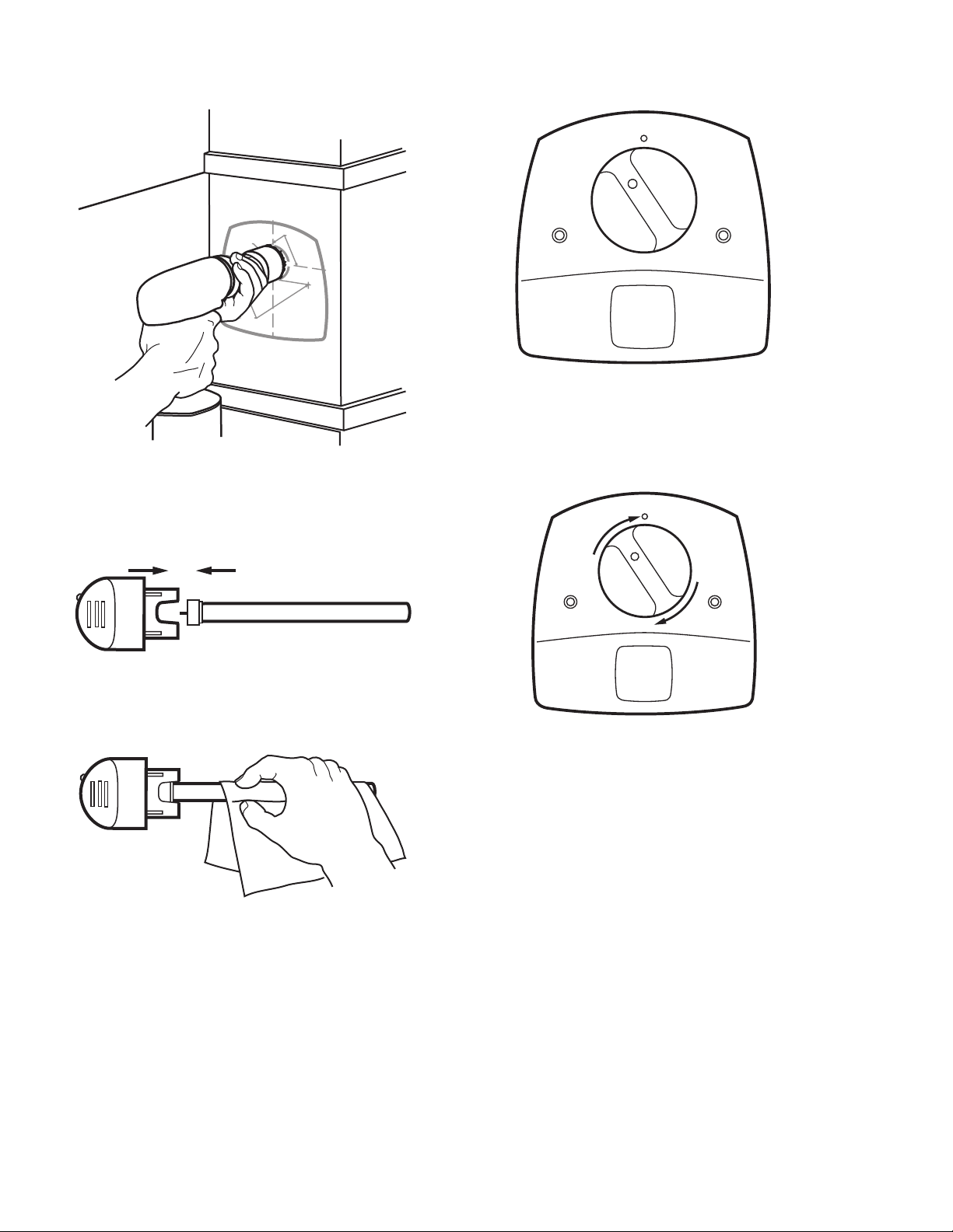
Fig. 5. Cut the bulb hole in the duct.
9. Insert the new lamp glass into the lamp handle by align-
ing the key and pushing straight together.
See Fig. 6.
Fig. 6. Place lamp glass in lamp handle.
10. If you touch the lamp glass with your hands, use a cloth
to wipe fingerprints from the glass. See Fig. 7.
Fig. 7. Use cloth to wipe fingerprints from glass.
11. Insert the bulb into the base unit with the lamp light indi-
cator at the eleven o’clock position (left of the raised
button on the unit cover). See Fig. 8.
12. Continue lightly pushing in on the lamp handle while
rotating it slowly counterclockwise. This should cause
the lamp handle to drop into the bottom of the lamp well.
Fig. 8. Insert bulb into base unit.
13. Rotate the lamp handle clockwise until it snaps into
place with the lamp indicator light aligned with the
raised button on the unit cover. See Fig. 9.
Fig. 9. Snap lamp into place.
14. Plug the cord into the nearby 120 Vac electrical outlet.
15. Reconnect the power to the HVAC system.
16. Choose a location on the adjacent HVAC equipment for
the HVAC maintenance label included in the air treat-
ment system packing box. Choose a location that a
future service technician can easily see during any
future HVAC maintenance or repair.
17. Adhere the HVAC maintenance safety label to the
HVAC equipment (selected in step 16) such as the fur-
nace access door, air cleaner or humidifier.
See Fig. 10.
C
E
N
T
E
R
O
F
2
I
N
.
(
51 M
M
)
C
E
N
T
E
R
O
F
2
I
N
.
(5
1
M
M
)
H
O
L
E
F
O
R
L
A
M
P
H
O
L
E
F
O
R
LA
M
P
3
/3
2
IN
.
(
3
M
M
) P
I
L
O
T
H
O
LE
S
3
/3
2
IN
.
(
3
M
M
) P
I
L
O
T
H
O
L
E
S
F
O
R
M
O
U
N
T
IN
G
S
C
R
E
W
S
F
O
R
M
O
U
N
T
I
N
G
S
C
R
E
W
S
A
L
IG
N
E
I
T
H
E
R
O
F
T
H
E
S
E
L
IN
E
S
A
L
I
GN
E
I
T
H
E
R
O
F
T
H
E
S
E
L
I
N
E
S
A
S
C
L
O
S
E
A
S
P
O
S
S
IB
L
E
TO
A
S
C
L
O
S
E
A
S
P
O
S
S
I
B
L
E
TO
D
U
C
T
C
E
N
T
E
R
L
IN
E
D
UCT
C
E
N
T
E
R
L
I
N
E
M18989
M22854A
M22843
M13603
M13604
Loading ...
Loading ...
Loading ...