Loading ...
Loading ...
Loading ...
ULTRAVIOLET SYSTEM
5 69-1859EFS—01
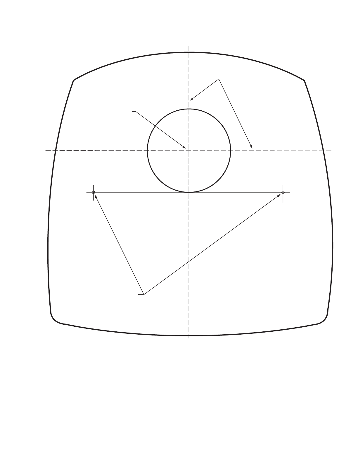
Fig. 4. Ultraviolet System template.
4. Use a 3/32 in. drill to provide pilot holes for the mounting
screws.
5. Be sure the duct surface is flat after all holes are drilled.
6. Position the entire base unit on the duct. Be sure the
bulb holes in the duct align with those in the unit to allow
bulb insertion.
7. Install the unit on to the duct using the two no.10, 2 in.
Phillips head sheet metal mounting screws provided.
8. Tighten the screws so the space between the case and
duct is sealed.
M18991
CENTER OF 2 IN. (51 MM)
HOLE FOR LAMP
3/32 IN. (3 MM) PILOT HOLES
FOR MOUNTING SCREWS
ALIGN EITHER OF THESE LINES
AS CLOSE AS POSSIBLE TO
DUCT CENTER LINE
Loading ...
Loading ...
Loading ...