Loading ...
Loading ...
Loading ...
ULTRAVIOLET SYSTEM
69-1859EFS—01 4
HOW TO INSTALL YOUR ULTRAVIOLET SYSTEM
When Installing this Product…
1. Read these instructions carefully. Failure to follow them
could damage the product or cause a hazardous
condition.
2. After installation is complete, check out product opera-
tion as provided in these instructions.
Selecting Mounting Location
Depending on installation location, the UV System can
operate as an Air Treatment System or as a Surface
Treatment System.
1. The UV System can be mounted in any orientation.
2. Choose a location that is readily accessible for regular
inspection and cleaning.
3. The UV Air Treatment System requires an easily-acces-
sible, flat mounting surface on the metal return air duct
of the HVAC system. The UV Surface Treatment Sys-
tem requires an easily-accessible, flat mounting surface
on the metal supply air duct of the HVAC system. The
UV Surface Treatment System must be located so the
lamp surrounds the evaporator coil and drip pan with
ultraviolet light.
4. The duct mounting location must be a minimum of 8 in.
wide. See Fig. 3.
5. The depth of the duct must accommodate the full length
of the ultraviolet bulb as shown in Fig. 3.
6. The unit should be located as far away as possible from
any rubber or plastic components, such as isolators, in
the duct.
IMPORTANT
If mounting options are limited, protect plastic or rub-
ber materials listed in CAUTION with ultraviolet-
resistant material such as aluminum foil duct tape.
7. The space adjacent to the mounting location must be
large enough to allow for ultraviolet bulb installation and
removal.
8. A 120V electrical outlet must be within range of the unit
to plug in the power cord.
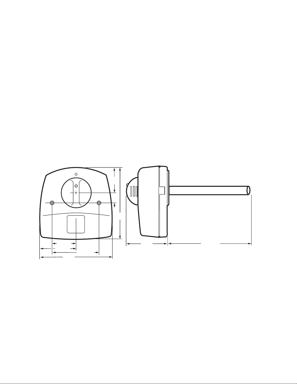
Fig. 3. Ultraviolet System dimensions in in. (mm).
Duct Mounting
Use the following instructions to mount the UV System on the
air duct of an HVAC system:
1. Disconnect power to the HVAC system before installing
the UV System.
2. Tape the template (Fig. 4) on the duct surface, centering
the bulb hole on the duct.
3. Cut the 2 in. bulb hole in the duct. See Fig 5. Remove
any burrs.
2-1/4 (57)
3-1/2 (89)
4-1/2 (114)
7 (178)
1
(25)
7
(178)
2-1/2
(64)
4 (102)
7-7/16 (188)
M18990
Loading ...
Loading ...
Loading ...