Loading ...
Loading ...
Loading ...
70
MULTI F / MULTI F MAX Outdoor Unit Installation Manual
Due to our policy of continuous product innovation, some specifications may change without notification.
©LG Electronics U.S.A., Inc., Englewood Cliffs, NJ. All rights reserved. “LG” is a registered trademark of LG Corp.
MULTI
F
MAX
MULTI
F
Error Code Description Indoor Unit Operation Status
00 No error ON
01 Indoor unit room temperature sensor error OFF
02 Indoor unit inlet pipe sensor error OFF
03 Controller error OFF
04 Drain pump error (optional) OFF
05 Communication error between indoor unit and outdoor units OFF
06 Indoor unit outlet pipe sensor error OFF
07 Different mode operation error OFF
09 Indoor unit EPROM error OFF
10 Indoor unit BLDC motor fan lock OFF
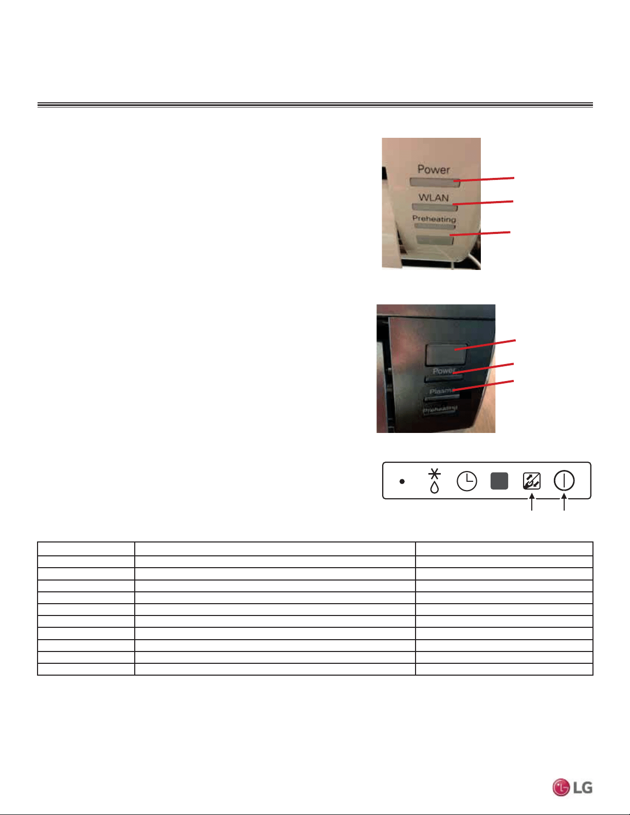
Receiver
LED 1
(UNITS PLACE)
LED 2
(TENS PLACE)
Figure 108: Standard Wall-Mounted Indoor Unit LEDs.
Figure 109: Art Cool Mirror Wall-Mounted Indoor Unit
LEDs.
Number of Blinks = Error Code
LED 1: Units PlaceLED 2: Tens Place
Error Codes
Troubleshooting Using Error Codes
Refer to Tables 44 and 45 for error codes that are generated from
the indoor and outdoor units. These codes indicate different types of
unit failures, assist in self-diagnosis, are the most common that will
manifest through these units. Error codes are displayed on indoor unit
LEDs, wired remote controllers, the outdoor unit PCB, and through LG
Monitoring View (LGMV) diagnostic software.
Systems may generate additional codes not listed here. Contact LG
Support if these types of errors are seen and a simple power down and
boot up has not corrected the issue. Do not attempt to fix the system
yourself.
• If two or more errors occur simultaneously, the highest error code
QXPEHULVGLVSOD\HG¿UVW
• After error is resolved, the error code does not display.
Decoding the Error Display
See images and table below for indoor unit error codes, location of
LEDs, and operation status.
The first and second number on the LED indicates error number. Ex-
ample: 21 = LED1 (Red light) 2x blink, LED2 (Green light) 1x blink.
Error Code Nomenclature Definitions
• MICOM: Non-volatile memory chip where unit setup information is
stored.
• EPROM: Non-volatile memory chip where device identification, size,
and factory defined default component operating parameters are
stored.
Figure 110: Ceiling Cassette Indoor Unit LEDs.
Table 44: Indoor Unit Error Codes.
TROUBLESHOOTING
LED 1
(UNITS PLACE)
LED 2
(TENS PLACE)
Receiver
Loading ...
Loading ...
Loading ...