Loading ...
Loading ...
Loading ...
33
General Installation Guidelines
Due to our policy of continuous product innovation, some specifications may change without notification.
©LG Electronics U.S.A., Inc., Englewood Cliffs, NJ. All rights reserved. “LG” is a registered trademark of LG Corp.
MULTI
F
MAX
MULTI
F
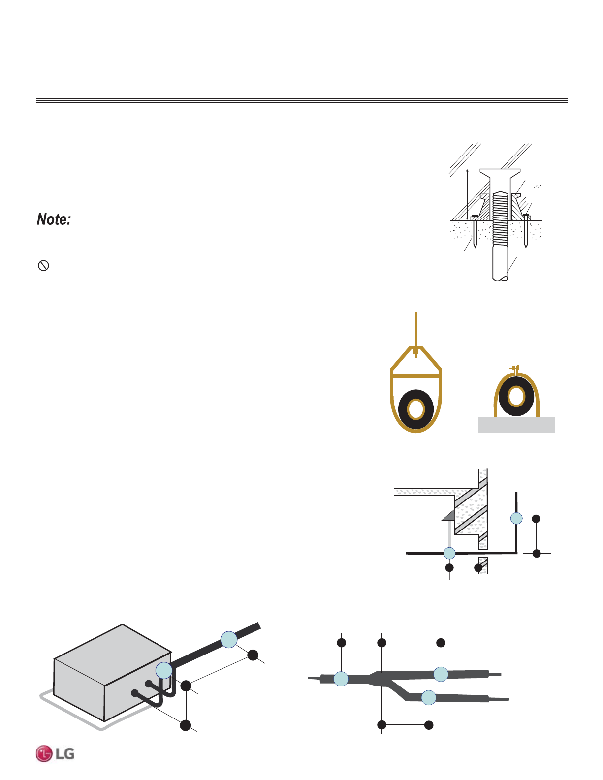
Pipe Supports
Figure 29: Installing an Insert Into
a Concrete Beam.
Piping Materials and Handling
Inserts and Pipe Supports
Inserts
An insert can be installed into a floor or beam before the concrete sets so that fittings such as ducts,
pipes, or suspension bolts can be added at a later time. Decide where the inserts should be placed
before support installation.
Figure 30: Pipe Hanger Details.
A
B
A + B ~ 12" – 19"
Max. 12" Max. 12"
Max. 12"
Figure 31: Typical Pipe Support Location—Change
in Pipe Direction.
Max. 12"
~ 12" – 19"
Pipe supports should never touch the pipe wall; supports shall be installed outside
(around) the primary pipe insulation jacket.
Insulate the pipe first because pipe supports shall be installed outside (around) the
primary pipe insulation jacket. Clevis hangers should be used with shields between the
hangers and insulation.
Field provided pipe supports should be designed to meet local codes. If allowed by
code, use fiber straps or split-ring hangers suspended from the ceiling on all-thread rods
(fiber straps or split ring hangers can be used as long as they do not compress the pipe
insulation). Place a second layer of insulation over the pipe insulation jacket to prevent
chafing and compression of the primary insulation within the confines of the support pipe
clamp.
A properly installed pipe system will have sufficient supports to avoid pipes from sagging
during the life of the system. As necessary, place supports closer for segments where
potential sagging could occur. Maximum spacing of pipe supports shall meet local
codes. If local codes do not specify pipe support spacing, pipe shall be supported a
maximum of five (5) feet on center for straight segments of pipe up to 3/4” outside
diameter size.
Wherever the pipe changes direction, place a hanger within twelve (12) inches on one
side and within twelve to nineteen (12 to 19) inches of the bend on the other side. Sup-
port piping at indoor units as shown. Support Y-Branch fittings as shown.
A properly installed pipe system should be adequately supported to avoid pipe sagging. Sagging pipes
become oil traps that lead to equipment malfunction.
Figure 32: Pipe Support at Indoor Unit.
Figure 33: Pipe Support at Y-branch Fitting.
GENERAL INSTALLATION GUIDELINES
Concrete Beam
Insert
Suspension Bolt
Polyblock /
Anti-Vibration
Material
Nail Securing
Polyblock
Loading ...
Loading ...
Loading ...