Loading ...
Loading ...
Loading ...
54
MULTI F / MULTI F MAX Outdoor Unit Installation Manual
Due to our policy of continuous product innovation, some specifications may change without notification.
©LG Electronics U.S.A., Inc., Englewood Cliffs, NJ. All rights reserved. “LG” is a registered trademark of LG Corp.
MULTI
F
MAX
MULTI
F
Figure 72: Multi F / Multi F MAX Outdoor and
Indoor / Branch Distribution Unit Wiring and
Communications Cable Diagram.
Ring Terminal
Power Wiring
Outdoor Unit Wiring Connection Guidelines
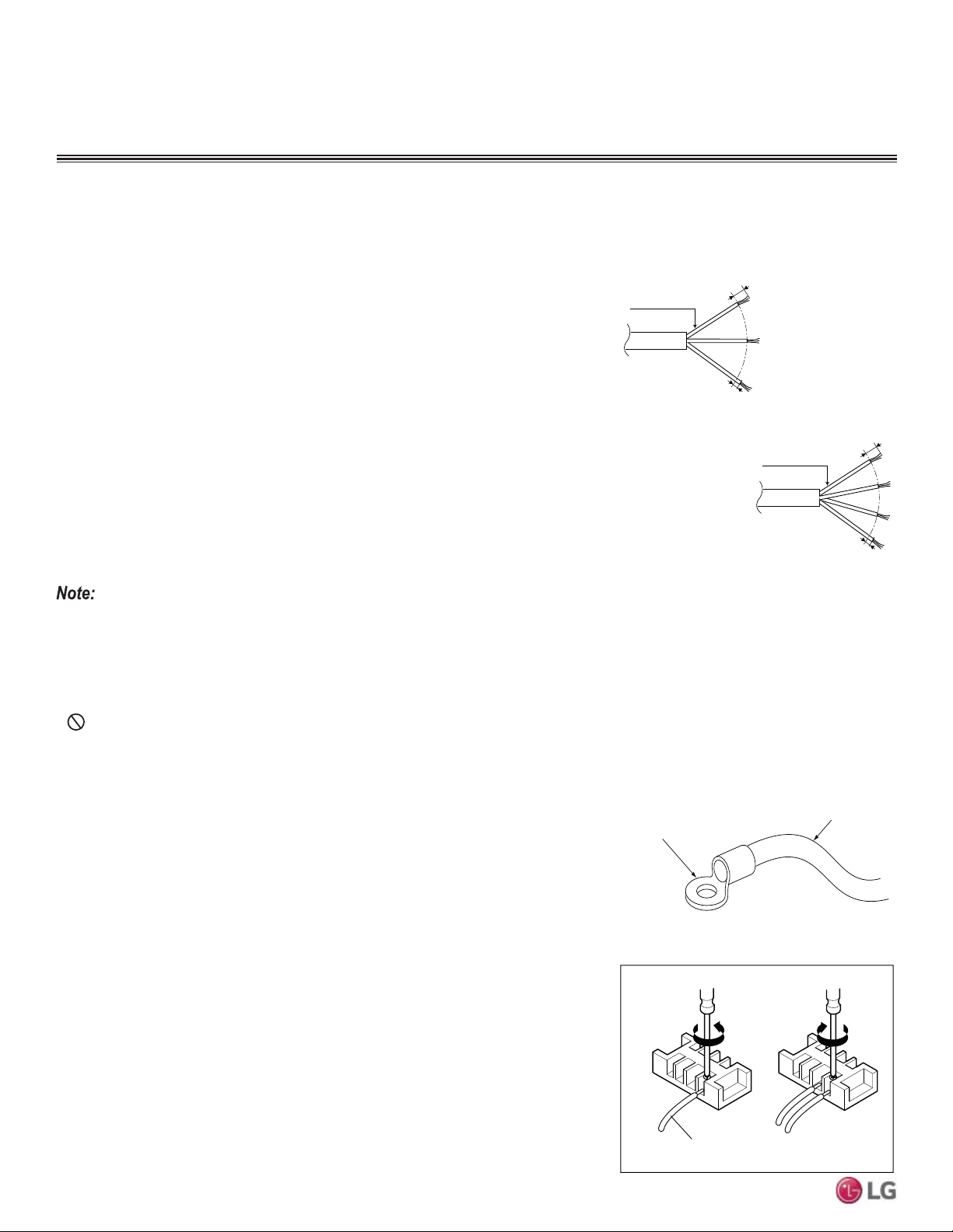
Best practice dictates using ring or spade terminals to terminate power wiring at the power
terminal block
To Install a Ring Terminal:
1. Trim the strand wiring with wire cutters or pliers, then strip the insulation to expose the
strand wiring to about 3/8 inch.
2. Using a ring terminal fastener or pliers, securely clamp a ring terminal to each stripped
wire end.
Figure 73: Close up of a Typical Ring Terminal
6/16” ± 2/16”
13/16”
GN/YL
Power Wiring, Ground
to Outdoor Unit
Power Wiring, Ground,
Communication Cable
From Outdoor Unit
To Indoor Unit or from the
Outdoor Unit to the Branch
Distribution Unit
13/16”
GN/YL
GN/YL = (Ground, Yellow)
6/16” ± 2/16”
WIRING
General Information
Connecting Cable
Connecting cable
Loosening the
terminal block
screw
Fastening the
wiring tightly
• Multi F Systems: All power wiring / communication cable to be minimum 18 AWG from the
outdoor unit to the indoor unit, stranded, shielded or unshielded (if shielded, it must be
grounded to the chassis of the outdoor unit only), and must comply with applicable local
and national codes.
• Multi F MAX Systems: All power wiring / communication cable to be minimum 16 AWG
from the outdoor unit to the BD unit, and 18 AWG from the BD unit to the indoor unit,
stranded, shielded or unshielded (if shielded, it must be grounded to the chassis of the
outdoor unit only), and must comply with applicable local and national codes.
• For power / communication wires between the Multi F and Multi F MAX outdoor units and
the indoor units / BD units (Multi F MAX systems only), use a four (4) conductor, strand-
ed, shielded or unshielded wire. If shielded, the wire must be grounded to the chassis at
the outdoor unit only.
• Insulation material as required by local code.
• 5DWHGIRUFRQWLQXRXVH[SRVXUHRIWHPSHUDWXUHVXSWR)
• Firmly attach the cable; provide slack but secure in a way to prevent
external forces from being imparted on the terminal block.
• Wiring should be completed without splices.
• Always verify the communication cable is connected to a communications terminal. Never apply line voltage power to the communication
cable connection. If contact is made, the PCBs may be damaged.
• The shield of the communications cable connecting the outdoor unit to the indoor units should be grounded only to the outdoor unit frame.
• Tie the shield of each cable segment together using a wire nut at the indoor unit. Maintain polarity throughout the communication network.
• Position the incoming power to the outdoor unit away from the power / communications cables from the outdoor unit to the indoor unit /
branch distribution unit (Multi F MAX systems only).
•
Never use a common multiple-core communications cable. Each communications bus shall be provided a separate cable (i.e., between
outdoor unit and indoor unit).
To Connect the Wiring to the Terminals:
1. Remove the terminal screws from the (outdoor unit, BD unit, or indoor unit) terminal plate
with a screwdriver.
2. Position the ring terminal around the terminal, place the terminal screw in the ring, and
tighten to the terminal plate using a screwdriver.
Figure 74: Tightening the Ring Terminal to the
Terminal Plate.
General Communication Cable Specifications
Loading ...
Loading ...
Loading ...