INSTALLATION
INSTRUCTIONS
FOR
YOUR
NEW
FREE-STANDING
ELECTRIC
RANGE
Before
you
begin
-
Read
these
instructions
completely
and
carefully.
IMPORTANT
-
Save
these
instructions
for
local
inspector's
use.
IMPORTANT
-
OBSERVE
ALL
GOVERNING
CODES
AND
ORDINANCES.
Note
to
Installer
-
Be
sure
to
leave
these
instructions
with
the
Consumer.
Note
to
Consumer
-
Keep
these
instructions
with
your
Use
and
Care
Book
for
future
reference.
FOR
YOUR
SAFETY
CAUTION:
For
Personal
Safetyremove
house
fuse
or
open
circuit
breaker
before
beginning
installation.
Failure
to
do
so
could
result
inserious
injury
or
even
death.
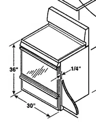
All
rough-in
and
spacing
dimensions
must
be
met
for
safe
use
of
your
range.
Electricity
to
the
range
can
be
disconnected
at
the
outlet
without
moving
the
range
if
the
outlet
is in
the
preferred
location
(remove
lower
drawer).
To
reduce
the
risk
of
burns
or
fire
when
reaching
over
hot
surface elements,
cabinet
storage
space
above
the
cooktop
should
be
avoided.
If
cabinet
storage
space
is
to
be
provided
above
the
cooktop,
the
risk
can
be
reduced
by
installing
a
range
hood
that
sticks
out
at
least
5"
beyond
the front
of
the
cabinets.
Cabinets
installed
above
a
cooktop
may
be
no
deeper
than
13".
Be
sure
your
appliance
is
properly
installed
and
grounded
by
a
qualified
technician.
WARNING:
Te
reduce
the
risk
of
tipping
the
appliance,
the
appliance must
be
secured
hy
properly
installed
anti-tip
device
packed
with
the
appliance.
31-10249
229C4053P003-3
-.
STABILITY
DEVICE
°
Ail
Ranges
Can
Tip
Injury
To
Persons
Could
Result
¢
Install
Anti-tip
Device
Packed
With
Range
:
°
See
Installation
Instructions
|
TOOLS
NEEDED:
Phillips
head
screwariver and
17
3/8"
open
end
or
adjustable
wrench
INSTALLATION
OF
THE
ANTI-TIP
DEVICE
Bracket
attaches
to
floor
or
wall
to
hold
either
right
or
left
rear
leg
leveler.
if
fastening
to
floor,
be
sure
that
screws
do
not
penetrate
electrical
wiring
or
plumbing.
Ifthis
cannot
be
determined,
use
shorter
screws
that
will
not
penetrate
through
flooring.
If
the
bracket
came
with
your
range,
it
is
shipped
inside
the
prepack
found
in
the
oven.
Remove
and
discard
the
shipping
screw
that
holds
the
bracket
and
then
follow
instructions
below.
1.
Decide
whether
the
bracket
will
be
installed
on
the
right
or
left
side
of
range
location.
2.
/f
the
bracket
side
of
the
range
is
adjacent
to
a
cabinet,
place
the
bracket
against
back
wall
and
cabinet
as
shown
in
Figure
7.
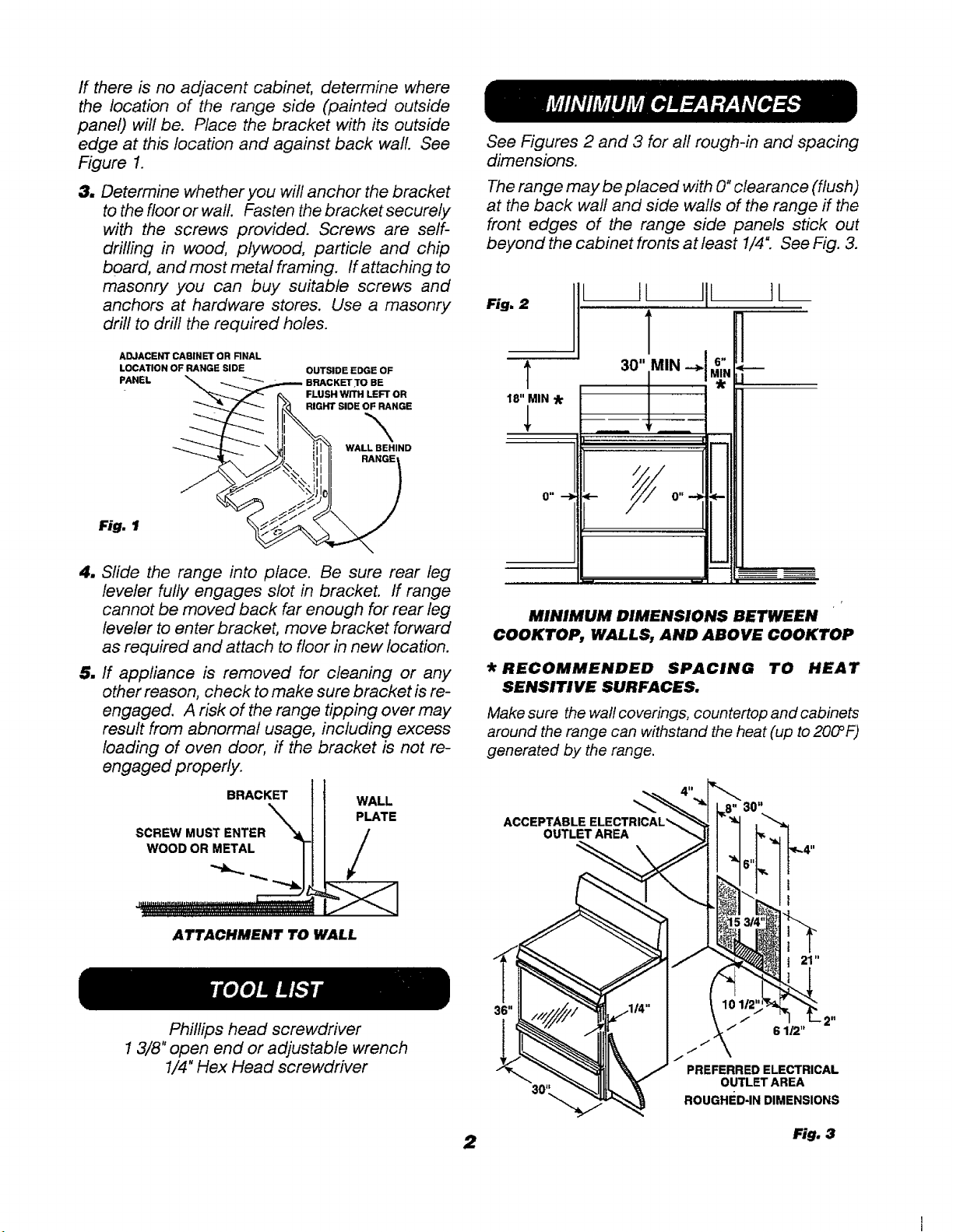
If
there
is
no
adjacent
cabinet,
determine
where
the
location
of
the
range
side
(painted
outside
panel)
will
be.
Place
the
bracket
with
its
outside
edge
at
this
location
and
against
back
wall.
See
Figure
7.
3.
Determine
whether
you
will
anchor
the
bracket
to
the
floor
or
wall.
Fasten
the
bracket
securely
with
the
screws
provided.
Screws
are
self-
drilling
in
wood,
plywood,
particle
and
chip
board,
and
most
metal
framing.
If
attaching
to
masonry
you
can
buy
suitable
screws
and
anchors
at
hardware
stores.
Use
a
masonry
drill
to
drill
the
required
holes.
ADJACENT
CASINET
OR FINAL
LOCATION
OF
RANGE
SIDE
PANEL
OUTSIDE
EDGE
OF
BRACKET
TO
BE
FLUSH
WITH
LEFT
OR
RIGHT
SIDE
OF
RANGE
WALL
BEHIND
RANGE
Fig.
1
4,
Slide
the
range
into
place.
Be
sure
rear
leg
leveler
fully
engages
slot
in
bracket.
If
range
cannot
be
moved
back
far
enough
for
rear
leg
leveler
to
enter
bracket,
move
bracket
forward
as
required
and
attach
to
floor
in
new
location.
§.
If
appliance
is
removed
for
cleaning
or
any
other
reason,
check
to
make
sure
bracket
is
re-
engaged.
A
risk
of
the
range
tipping
over
may
result
from
abnormal
usage,
including
excess
loading
of
aven
door,
if
the
bracket
is
not
re-
engaged
properly.
BRACKET
SCREW
MUST
ENTER
WOOD
OR
METAL
ATTACHMENT
TO
WALL
|
TOOLLIST
Phillips
head
screwdriver
1
3/8"
open
end
or
adjustable
wrench
1/4"
Hex
Head
screwdriver
MINIMUM
CLEARANCES
See
Figures
2
and
3
for
all
rough-in
and
spacing
dimensions.
The
range
may
be
placed
with
0"
clearance
(flush)
at
the
back
wall
and
side
walls
of
the
range
if
the
front
edges
of
the
range
side
panels
stick
out
beyond
the
cabinet
fronts
at
least
1/4".
See
Fig.
3.
||
Fig.
2
|
=
18"
MIN
*&
||
30"
MIN
—>|
6,
*
MINIMUM
DIMENSIONS
BETWEEN
_
COOKTOP,
WALLS,
AND
ABOVE
COOKTOP
*
RECOMMENDED
SPACING
TO
HEAT
SENSITIVE
SURFACES.
Make
sure
the
wall
coverings,
countertop
and
cabinets
around
the
range
can
withstand
the
heat
(up
to
200°F)
generated
by
the
range.
ACCEPTASLE
ELECTRICAL
OUTLET
AREA
“
PREFERRED
ELECTRICAL
OUTLET
AREA
ROUGHED-IN
DIMENSIONS
Fig.
3
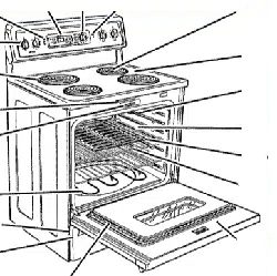
PREPARATION
«
Remove
ail
tape
and
packaging.
Remove
clear
plastic
film
that
covers
some
parts
(around
glass
oven
doors,
side
trim)
and
any
tape
or
packaging
from
inside
the
oven.
*
Remove
the
accessory
pack
from
the
oven.
*
Check
to
see
if
any
range
parts
have
come
loose
during
shipping.
(
REMOVING
PACKAGING
MATERIAL
Any
packaging
materials
must
he
removed
during
installation.
This
willinclude
adhesive
tape,
wire
ties,
catdhoard
and
protective
plastic.
Failure
to
remove
these
materials
could
result
in
damage
to
the
appliance
once
the
appliance
has
been
turned
on
and
surfaces
have
heated.
Nee
-
ELECTRICAL
REQUIREMENTS
This
appliance
must
be
supplied
with
the
proper
voltage
and
frequency,
and
connected
to
an
individual,
properly
grounded
branch
circuit,
protecied
by
a
circuit
breaker
or
time
delay
fuse,
as
noted
on
rating
piate.
Wiring
must
conform
to
National
Electrical
Codes.
If
the
electric
service
provided
does
not
meet
the
above
specifications,
call
a
licensed
electrician.
You
can
geta
copy
of
the
National
Electrical
Code,
ANSI/NFPA
No.
70-Latest
Edition
by
writing:
National
Fire
Protection
Association
Battery
March
Park
Quincy,
MA
02269
Effective
January
1,
1996,
the
National
Electrical
Code
requires
that
new
or
rewired
construction
utilize
a
4-
conductor
connection
to
an electric
range.
When
installing
an
electric
range
in
a
new
construction,
follow
the
instructions
in
NEW
CONSTRUCTION
AND
FOUR-CONDUCTOR
BRANCH
CIRCUIT
CONNECTION.
If
you
fail
to
wire
your
range
in
accordance
with
governing
codes,
you
may
create
a
hazardous
condition.
You
must
use
a
three-wire,
single-phase
AC
120/240
Volt
or
208Y/120
Volt,
60
Hertz
electrical
system
to
operate
your
range.
.
Use
#8
gauge
wire
and
40
Amp
fuse
or
circuit
breaker
for
120/240
Volt
and
208Y/120
Volt
systerns.
The
range
connector
biock
is
approved
for
copper
wire
connection
only.
If
you
are
connecting
to
aluminum
house
wiring,
you
must
use
special
UL
approved
connectors
for
joining
copper
to
aluminum.
Bed
Caner
ene
e116)
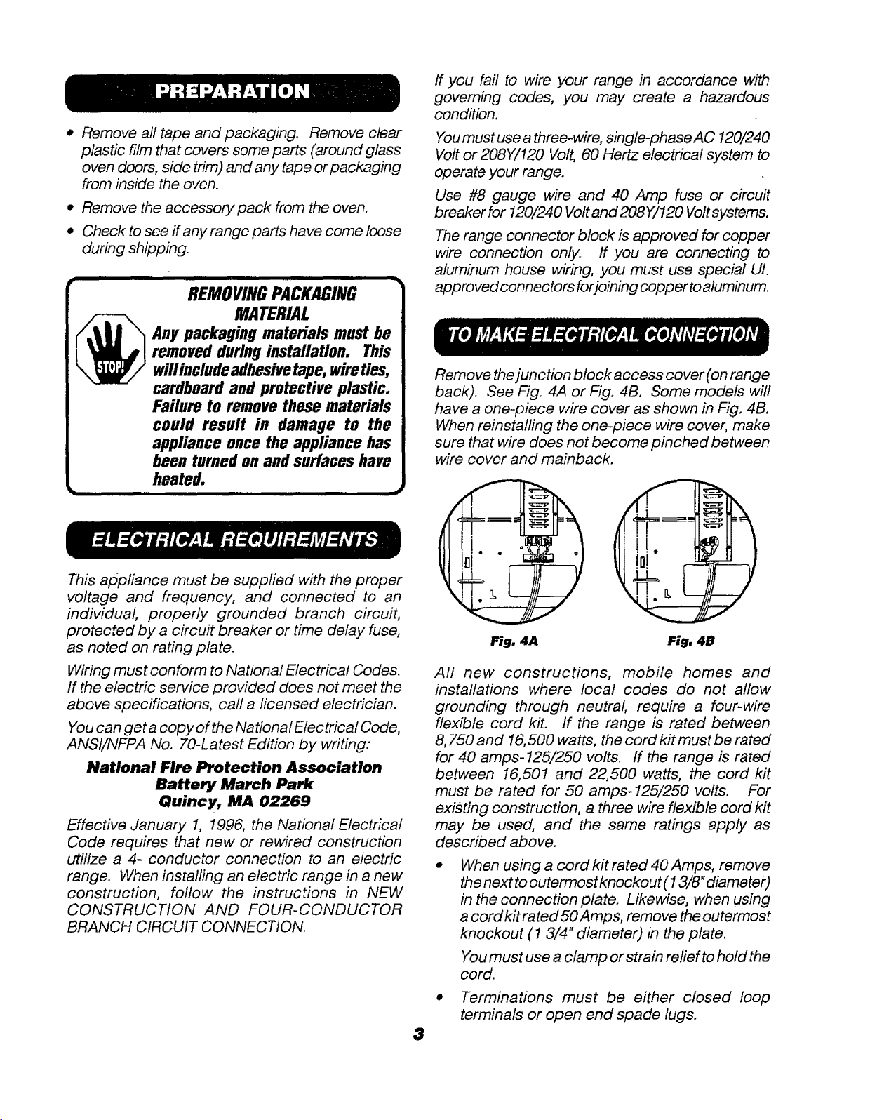
Remove
the
junction
block
access
cover
(on
range
back).
See
Fig.
4A
or Fig.
4B.
Some
models
will
have
a
one-piece
wire
cover
as
shown
in
Fig.
4B.
When
reinstalling
the
one-piece
wire
cover,
make
sure
that
wire
does
not
become
pinched
between
wire
cover
and
mainback.
All
new
constructions,
mobile
homes
and
installations
where
local
codes
do
not
allow
grounding
through
neutral,
require
a
four-wire
flexible
cord
kit.
ff
the
range
is
rated
between
8,750
and
16,500
watis,
the
cord
kit
must
be
rated
for
40
amps-125/250
volts.
If
the
range
is
rated
between
16,501
and
22,500
watts,
the
cord
kit
must
be
rated
for
50
amps-125/250
volts.
For
existing
construction,
a
three
wire
flexible
cord
kit
may
be
used,
and
the
same
ratings
apply
as
described
above.
e
When
using
a
cord
kit
rated
40
Amps,
remove
the
next
to
outermost
knockout
(1
3/8"
diameter)
in
the
connection
plate.
Likewise,
when
using
acordkitrated50
Amps,
remove
the
outermost
knockout
(1
3/4"
diameter)
in
the
plate.
You
must
use
a
clamp
or
strain
relief
to
hold
the
cord.
*
Terminations
must
be
either
closed
loop
terminals
or
open
end
spade
lugs.
Bet
Ae
ea
Eee
Sees!
0.0);
/'//-|
CORD
CONNECTION
KIT
»
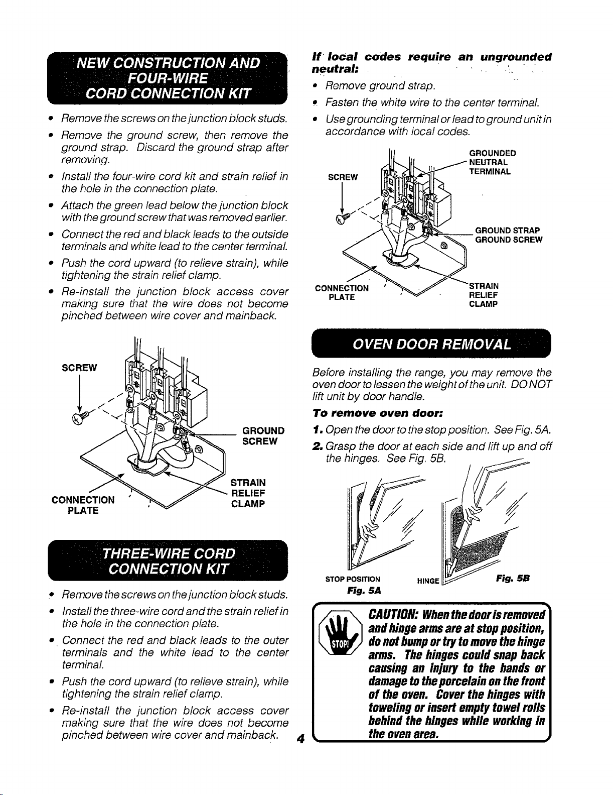
Remove
the
screws
on
the
junction
block
studs,
Remove
the
ground
screw,
then
remove
the
ground
strap.
Discard
the
ground
strap
after
removing.
Install the
four-wire
cord
kit
and
strain
relief
in
the
hole
in
the
connection
plate.
Attach
the
green
lead
below
the
junction
block
with
the
ground
screw
that
was
removed
earlier.
Connect
the
red
and
black leads
to
the
outside
terminals
and
white
ead
to
the
center
terminal.
Push
the
cord
upward
(to
relieve
strain),
while
tightening
the
strain
relief
clamp.
Re-install
the
function
block
access
cover
making
sure
that the
wire
does
not
become
pinched
between
wire
cover
and
mainback.
GROUND
SCREW
STRAIN
;
RELIEF
CONNECTION
CLAMP
PLATE
_
THREE-WIRECORD
eee)
erro)
ae
Remove
the
screws
on
the
junction
block
studs.
Install the
three-wire
cord
and
the
strain
relief
in
the
hole
in
the
connection
plate.
_Connect
the
red
and
black
leads
to
the
outer
terminalis
and
the
white
lead
to
the
center
terminal.
Push
the
cord
upward
(to
relieve
strain),
while
tightening
the
strain
relief
clamp.
Re-install
the
junction
block
access
cover
making
sure
that
the
wire
does
not
become
pinched
between
wire
cover
and
mainback.
4
if-local
codes
require
an
ungrounded
neutral:
.
Fe
e
Remove
ground
strap.
¢
Fasten
the
white
wire
to
the
center
terminal.
©
Use
grounding
terminal
or
lead
to
ground
unit
in
accordance
with
local
codes.
GROUNDED
NEUTRAL
TERMINAL
GROUND
STRAP
GROUND
SCREW
CONNECTION
PLATE
RELIEF
CLAMP
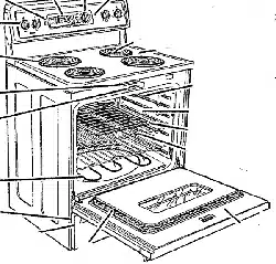
OVEN
DOOR
REMOVAL
Before
installing
the
range,
you
may
remove
the
oven
door
to
lessen
the
weight
of
the
unit.
DO
NOT
lift
unit
by
door
handle.
To
remove
oven
door:
1.
Open
the
door
to
the
stop
position.
See
Fig.
5A.
2.
Grasp
the
door
at
each
side
and
lift
up
and
off
the
hinges.
See
Fig.
5B.
STOP
POSITION
HINGE
Fig.
5A
CAUTION:
When
the
dooris
removed
and
hinge
arms
are
at
stop
position,
do
not
bump
or
try
to
move
the
hinge
arms.
The
hinges
could
snap
back
causing
an
injury
to
the
hands
or
damage
to
the
porcelain
on
the
front
of
the
oven.
Cover
the
hinges
with
toweling
or
insert
empty
towel
rolls
behind
the
hinges
while
working
in
L
the
oven
area.
J
---
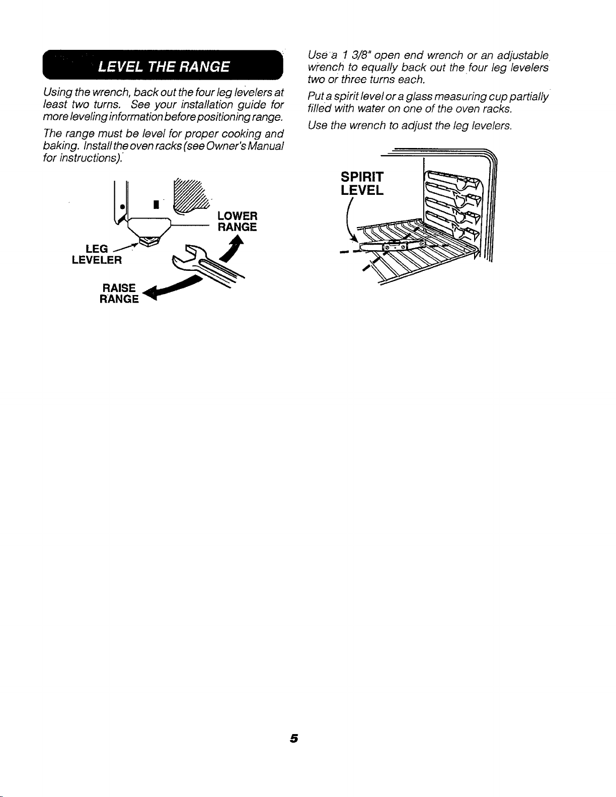
LEVEL
THE
RANGE
Using
the
wrench,
back
out
the
four
leg
levelers
at
least
two
turns.
See
your
installation
guide
for
more
leveling
information
before
positioning
range.
The
range
must
be
level
for
proper
cooking
and
baking.
Install
the
oven
racks
(see
Owner's
Manual
for
instructions).
LOWER
RANGE
oN
LEG
—”
LEVELER
RAISE
RANGE
Use'a
1
3/8"
apen
end
wrench
or
an
adjustable.
wrench
to
equally
back
out
the
four
leg
levelers
two
or
three
turns
each.
Put
a
spirit
level
or
a
glass
measuring
cup
partially
filled
with
water
on
one
of
the
oven
racks.
Use
the
wrench
to
adjust
the
leg
levelers.

NOTES

NOTES

ey
ae
:
Recycted
Papar
31-10249
an
229C4053P003-3
8
—
Printed
in
the
United States
—
INSTRUCCIONES
PARA
LA
INSTALACION
DE
SU
NUEVA
ESTUFA
ELECTRICA
INDEPENDIENTE
Antes
de
empezar
-
Lea
estas
instrucciones
completa
y
cuidadosamente.
IMPORTANTE
-
Guarde
estas
instrucciones
para
el
uso
del
inspector
de
su
localidad.
IMPORTANTE
-
RESPETE
TODOS
LOS
CODIGOS
Y
ORDENANZAS
VIGENTES.
Nota
para
el
instalador
-
Cerciérese
de
dejar
estas
instrucciones
con
el
cliente.
Nota
para
el
consumidor
-
Guarde
estas
instrucciones
junto con
su
libro
de
Uso
y
Cuidado,
por
si
las
necesita
en
un
futuro.
_
MEDIDAS
DE
SEGURIDAD
PRECAUCION:
Para
su
seguridad
personal,
saque
el
fusible
eléctrice
de
la
casa
o
apague
el
interruptor
del
circuito
abierto
antes
de
comenzar
la
instalacion.
Todas
las
dirnensiones
y
espacios
aproximados
deben
satisfacerse
para
ef
uso
seguro
de
su
estufa.
La
electricidad
que
alimenia
la
estufa
puede
desconeciarse
de
fa
torma
de
corriente
moviendo
la
estufa
si la
toma
de
corriente
se
encuentra
en
el
lugar
preferido
(quite
el
cajon
inferior).
Para
reducir
ef
riesgo
de
quernaduras
o
fuego
cuando
pase
el
brazo
sobre
elementos
calientes
de
la
superficie,
debe
evitar
poner
gabinetes
o
alacenas
sobre
/a
estufa.
Si
ya
esidn
instalados
sobre
la
estufa,
puede
reducir
el
riesgo
instalando
una
barra
que
sobresaiga
por
lo
menos
5"
a
partir
del
frente
del
gabinete.
Los
gabinetes
instalados
sobre
la
estufa
no
deben
tener
una
profundidad
mayor
de
13”.
Cercidrese
de
que
su
aparato
haya
sido
correctamente
instalado
y
que
haga
tierra
por
un
técnico
calificado.
jADVERTENCIA!:
Para
reducir
el
riesgo
de
volcar
fa
estufa,
ésta
debe
instalarse
de
manera
adecuada
mediante
el
dispositive
anti-voleaduras
que
se
incluye
con
el
aparato.
31-10249
229C4053P003-3
DISPOSITIVO
ANTI-VOLCADURAS
A
WY
arer
©
TODAS
LAS
ESTUFAS
PUEDEN
VOLCARSE
®
ALGUIEN
PUEDE
RESULTAR
HERIDO
*®
INSTALE
EL
DISPOSITIVO
ANTI-
VOLCADURAS
QUE
VIENE
EMPACADO
JUNTO
CON
LA?
ESTUFA
e
LEALAS
INSTRUCCIONES
eee
s
aren
eyes
Caen
HERRAMIENTAS
NECESARIAS:
Destornillador
de
cabeza
Phillips
y
llave
de
tuercas
o
llave
inglesa
de
1
3/8"
INSTALACION
DEL
DISPOSITIVO
CONTRA
VOLACADURAS
Fije
ef
sujelador
al
suelo
o a
la
pared
para
sostener
ya
sea
la
pata
niveladora
posterior
derecha
o
izquierda.
Si
lofiiaal
suelo,
asegurese
de
que
los
tornillos
no
penetren
hasta
donde
haya
cables
elétricos
o
de
tubos
de
plomerfa.
Si
no
puede
determinar
lo
anterior,
utilice
tornillos
mas
cortos
que
no
alcancen
a
atravesar
del
todo
el
recubrimiento
de!
suelo.
Si
el
sujetador
viene
junto
con
su
estufa,
se
encuentra
atornillado
en
/a
parte
posterior
de
fa
estufa.
Quife
y
tire
el
tornilio
que
sé
uso
para
el
traslado
y
que
sostiene
el
sujetador
y
siga
las
instrucciones
que
aparecen
mas
abajo.
1.
Decida
si
ef
sujetador
se
instalara
el
lado
izquierdo
o
derecho
de
Ia
estufa.
2.
Si
ef
lado
donde
va
ef
sujetador
esta
junto
a
un
gabinete,
coloque
ef
sujetador
contra
la
pared
posterior
y
el
gabinete,
como
se
muestra
en
la
figura
7.
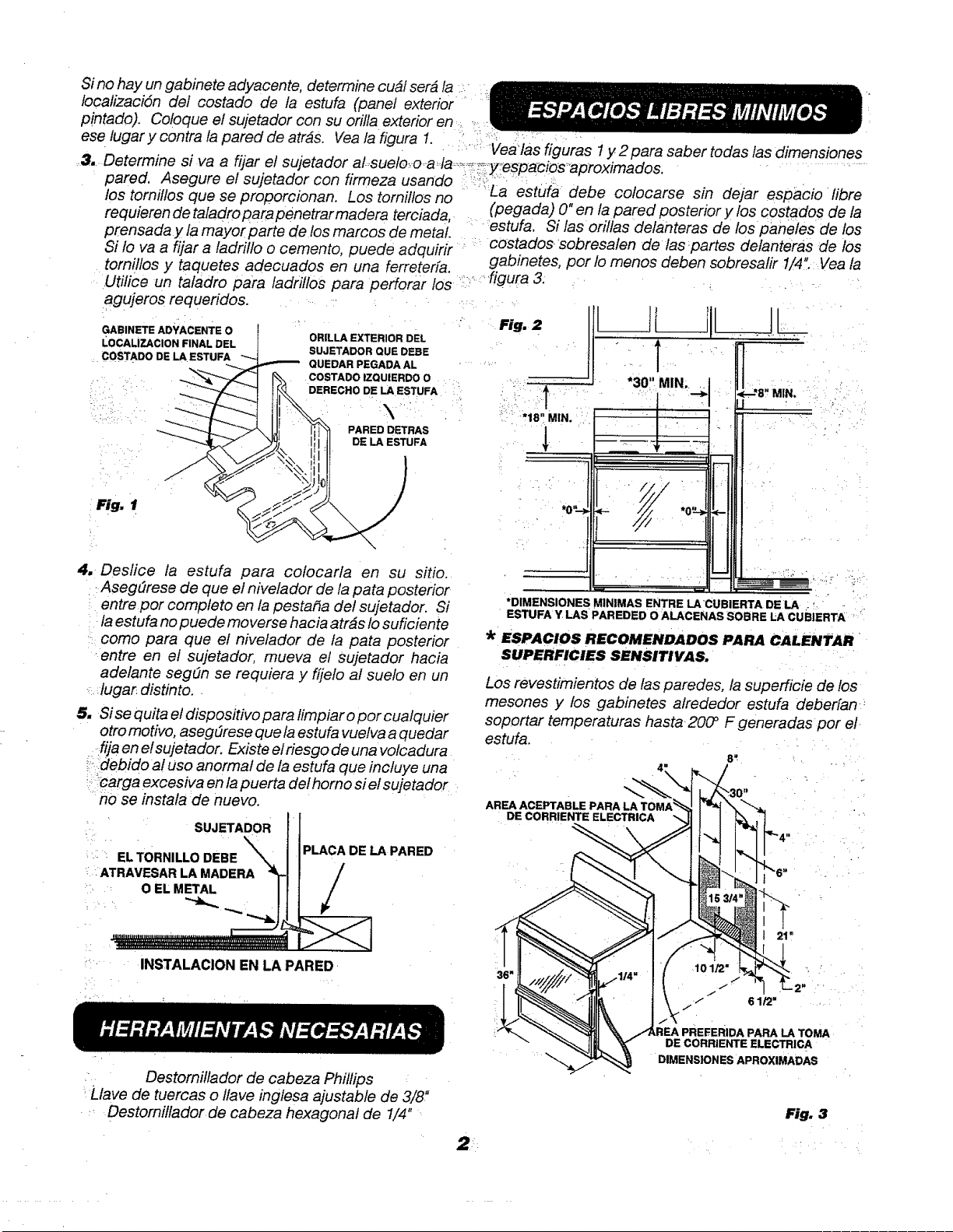
Sino
hay
un
gabinete
adyacente,
determine
cudl
serd
la
localizacién
del
costado
de
la
estufa
(panel
exterior
pintado).
Coloque
e/
sujetador
con
su
orilla
exterior
en
4
ese
lugar
y
contra
la
pared
de
atraés.
Vea
la
figura
1.
3...Determine
si
va
a
fijar
el
sujetador
al-suelo-0-ada:
pared.
Asegure
el
sujetador
con
firmeza
usando
—
los
tornillos
que
se
proporcionan.
Los
tornillos
no
requieren
de
taladro
para
pénetrar
madera
terciada,.
prensada
y
la
mayor
parte
de
los
marcos
de
metal.
Si
fo
va
a
fijar
a
ladrillo
o
cemento,
puede
adquirir
°
tornillos
y
taquetes
adecuados
en
una
ferreteria.
agujeros
requeridos.
oo
GABINETE
ADYACENTE
0
ORILLA
EXTERIOR
DEL
LOCALIZACION
FINAL
DEL
COSTADO
DE
LA
ESTUFA
SUJETADOR
QUE
DEBE
cae
:
QUEDAR
PEGADA
AL
COSTADO
IZQUIERDO
0
DERECHO
DE
LA
ESTUFA
PARED
DETRAS
DE
LA
ESTUFA
Fig.
1
4,
Deslice
ia
estufa
para
colocarla
en
su
sitio.
_
Asegurese
de
que
el
nivelador
de
la
pata
posterior
"entre
por
completo
en
la
pestafia
del
sujetador.
Si
Jaestufa
no
puede
moverse
hacia
atras
lo
suficiente
=,
COMO
para
que
el
nivelador
de
fa
pata
posterior
‘entre
en
ef
sujetador,
mueva
el
sujetador
hacia
adelante
segtin
se
requiera
y
fijelo
al
suelo
en
un
«dugar.
distinto.
.
5.
Sise
quita
el
dispositivo
para
limpiar
o
por
cualquier
otro
motivo,
asegurese
que
la
estufa
vuelva
a
quedar
_tijaen
el
sujetador.
Existe
el
riesgo
de
una
volcadura
~=.debido
al
uso
anormal
de
la
estufa
que
incluye
una
»-arga
excesiva
en
la
puerta
del
horno
siel
sujetador
.
no
se
instala
de
nuevo.
SUJETADOR
“°
EL
TORNILLO
DEBE
PLACA
DE
LA
PARED
"
ATRAVESAR
LA
MADERA
O
EL
METAL
oe
rc
INSTALACION
EN
LA
PARED
-
HERRAMIENTAS
NECESARIAS
|
o
Destornillador
de
cabeza
Phillips
'Liave
de
tuercas
o
llave
inglesa
ajustable
de
3/8"
:
Destornillador
de
cabeza
hexagonal
de
1/4"~
ESPACIOS
LIBRES
MINIMOS
‘Vea
las
figuras
1
y.2
para
saber
todas
las
dimensiones
"espacios
aproximados,
a
estufa
debe
colocarse
sin
dejar
espacio
libre
(pegada)
0"
en
la
pared
posterior
y
los
costados
de
Ia
“estufa,
Si
las
orillas
delanteras
de
los
paneles
de
los
*
costados
sobresalen
de
las
‘partes
delanteras
de
los
gabinetes,
por
lo
menos
deben
sobresalir
1/4".
Vea
fa
*30"
mn
I
Utilice
un
taladro
para
ladrillos
para
perforar
los
°°
figura
3.
.
Fig.
2
gg"
MIN,
*DIMENSIONES
MINIMAS
ENTRE
LA
CUBIERTA
DELA
;
a
ESTUFA
Y.LAS
PAREDED
0
ALACENAS
SOBRE
LA
CUBIERTA
et
*
ESPACIOS
RECOMENDADOS
PARA
CALENTAR
,
SUPERFICIES
SENSITIVAS.
Los
revestimientos
de
las
paredes,
la
superficie
de
los
mesones
y
los
gabinetes
alrededor
estufa
deberfan::
soportar
temperaturas
hasta
200°
F
generadas
por
el.
estufa.
ns
AREA
ACEPTABLE
PARA
LA
TOMA
DE
CORRIENTE
ELECTRICA
“
Lo
.
AREA
PREFERIDA
PARA
LA
TOMA
DE
COARIENTE
ELECTRICA
DIMENSIONES
APROXIMADAS
Fig.
3
©
Quite
toda
fa
cinta
adhesiva
y
los
empaques,
Retire
las
hojas
de
plastico
transparente
que
cubren
algunas
partes
(alrededor
de
las
puertas
de
vicrio
del
horno,
los
marcos
lalerales),
cualquier
cinta
o
empaque
que
se
encuentre
en
ef
interior
del
horno.
«
Retire
los
accesorios
de
empaque
que
estén
en
el
horno.
e
Verifique
si
alguna
parte
de
la
estufa
se
aflojé
durante
el
trasiado.
r=
REMUEVA
LAS
MATERIALES
DE
EMPAQUE
Todos
las
materiales
de
empaque
debe
ser
removidos
durante
fa
instalacién.
Esta
incluye
cintas
adhesivas,
amarras
de
alambre,
cartén
y
plasticos
protectores.
Si
estes
materiales
no
se
Sacan
podria
resultar
en
daiios
al
aparate
una
vez
que
fa
estufa
se
encienda
y
las
superficies
se
ealienten.
|
_
REQUERIMIENTOS
ELECTRICOS
Aeste
aparato
electrodornéstico
se
le
debe
suministrar
ef
vollaje yla
frecuencia
adecuados,
y
debe
estar
conectado
a
un
circulto
individual,
correctamente
aterrizado,
protegido
por
un
interrupior
de
circuito
o
un
fusible
con
mecanismo
de
demora,
como
se
observa
en
la
placa
de
condiciones
de
funcionamiento.
El
cableado
debe
estar
en
conformidad
con
los
Cédigos
Eléctricos
Nacionales
(National
Electrical
Codes).
Si
ef
servicio
eléctrico
que
sé
proporciona
no
satisface
las
especificaciones
antes
rmencionadas,
llame
a
un
electricista
aulorizado.
Puede
obtener
una
copia
del
Codigo
Eléctrico
Nacional
(National
Electrical
Code)ANSII
nipa
Nam.
70,
ultima
edicion,
si
escribe
a:
National
Fire
Protection
Association
Battery
March
Park
Quincy,,
MA
02268
Efectivo
el
1
de
enero,
1996,
el
Codigo
Eléctrico
Nacional
requiere
que
la
construcién
del
alambrado
nuevo
o
realambrado
utilice
una
conexién
de
4
conductores
a
un
aparato
electrodoméstico.
Cuando
instale
una
estufa
eléctrica
en
una
construccién
nueva,
sigalas
instrucciones
en
CONEXION
EN
UNA
CONSTRUCCION
NUEVA
Y
EN
CIRCUITO
CONDUCTOR
DE
CUATRO
RAMAS.
Si
no
conecta
su
estufa
de
acuerdo
con
los
cédigos
vigentes,
puede
estar
creando
una
condicién
peligrosa.
Debe
usar
un
cable
de
tres
polos,
de
una
fase,
de
120/
240
voltios
de
AC
o
un
sistema
208Y/120
voltios,
60
Hertz
para
operar
su
estufa.
La
caja
de
conexién
de
la
estufa
esta
aprobada
sdilo
para
cables
de
cobre.
Sila
va
conectar
a
un
cableado
doméstico
de
aluminio,
debe
utilizar
conectores
U.L.
aprobados
para
conectar
el
cobre
con
el
aluminia.
Ra
ao
8
eee
oe)
-
ELECTRICA
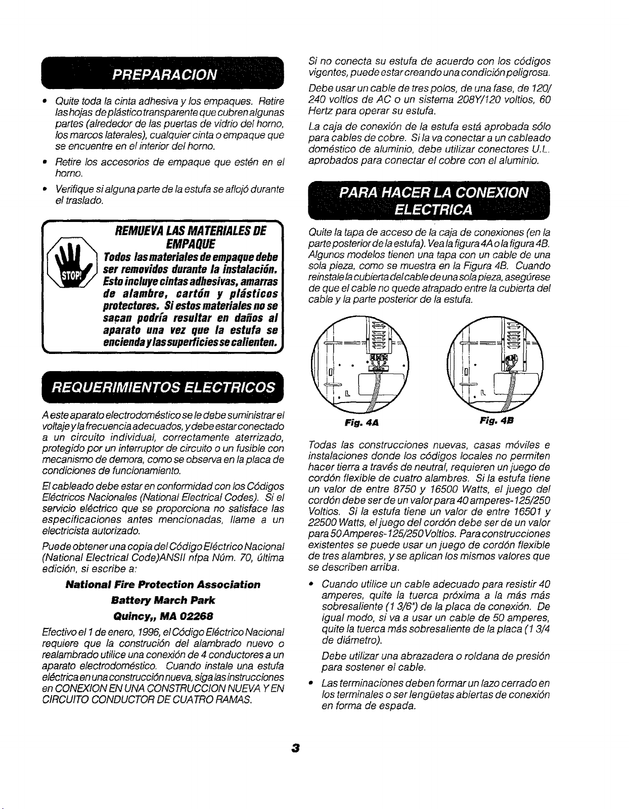
Quite
la
iapa
de
acceso
de
fa
caja
de
conexiones
(en
la
parte
posterior
de
Ja
estufa).
Vea
la
figura
4A
ola
figura
4B.
Algunos
modelos
tienen
una
tapa
con
un
cable
de
una
sola
pleza,
como
se
muestra
en
/a
Figura
4B.
Cuando
reinstate
la
cubierta
delcable
de
una
sola
pieza,
asequrese
de
que
el
cable
no
quede
atrapado
entre
la
cubierta
del
cable
y
la
parte
posterior
de
Ja
estufa.
Todas
fas
construcciones
nuevas,
casas
moviles
e
instalaciones
donde
los
cédigos
locales
no
permiten
hacer
tierra
a
través
de
neutral,
requieren
un
juego
de
cordon
flexible
de
cuatro
alambres.
Si
la
estula
tiene
un valor
de
enire
8750
y
16500
Watts,
el
juego
del
cordon
debe
ser
de
un
valor
para
40
amperes-
125/250
Voltios.
Si
la
estufa
tiene un
valor
de
entre
16507
y
22500
Watts,
el
juego
del
cordén
debe
ser
de
un
valor
para
50
Amperes-
125/250
Voltios.
Para
construcciones
existentes
se
puede
usar
un
juego
de
cordén
flexible
de
tres
alambres,
y
se
aplican
los
mismos
valores
que
se
describen
arriba.
*
Cuando
utilice
un
cable
adecuado
para
resistir
40
amperes,
quite
la
tuerca
préxima
a
la
mas
mas
sobresaliente
(1
3/6")
de
la
placa
de
conexidn.
De
igual
modo,
si
va
a
usar
un
cable
de
50
arnperes,
quite
la
tuerca
mas
sobresaliente
de
la
placa
(1
3/4
de
diametro).
Debe
utilizar
una
abrazadera
o
roldana
de
presién
para
sostener
el
cable.
©
Las
terminaciones
deben
formar
un
lazo
cerrado
en
los
terminales
o
ser
lengdetas
abjertas
de
conexion
en
forma
de
espada.
~
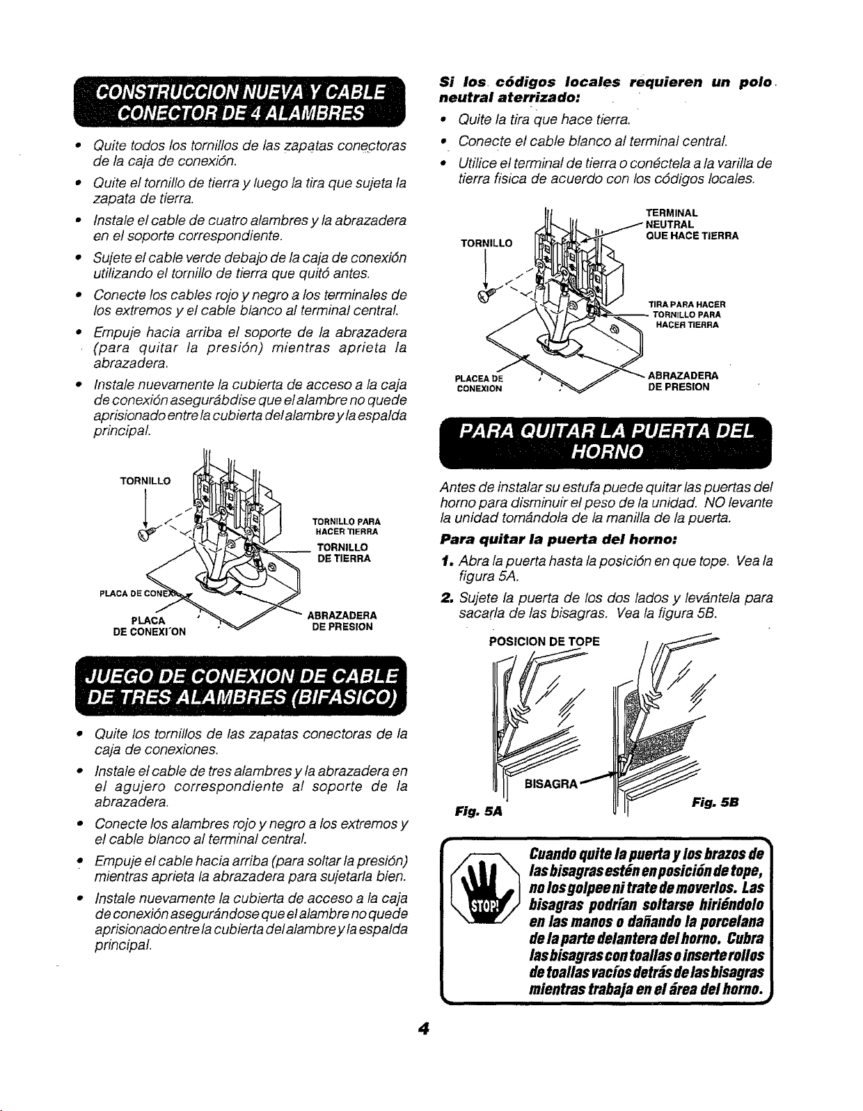
CONSTRUCCION
NUEVA
Y
CABLE
~
_
CONECTOR
DE
4
ALAMBRES
*
Quite
todos
fos
tornillos
de
las
zapatas
conectoras
de
la
caja
de
conexian.
*
Quite
el
tornilio
de
tierra
y
luego
Ia
tira
que
sujeta
la
zapata
de
tierra.
e
instale
el
cable
de
cuatro
alambres
y
la
abrazadera
en
ef
soporte
correspondiente.
¢
Sufete
el
cable
verde
debajo
de
la
caja de
conexion
utilizando
ef
tornillo
de
tierra
que
quité
antes.
*
Conecte
los
cables
rojo
y
negro
a
los
terminales
de
los
extremos
y
el
cable
blanco
al
terminal
central.
*
Empuje
hacia
arriba
el
soporte
de
ja
abrazadera
|
(para
quitar
ja
presién)
mientras
aprieta
la
abrazadera.
*
Instale
nuevamente
la
cubierta
de
acceso
a
la
caja
de
conexién
asegurabdise
que
elalambre
no
quede
aprisionado
entre
la
cubierta
del
alarnbre
y
laespalda
principal.
TORNILLO
PARA
HACER
TIERRA
TORNILLO
DE
TIERRA
PLACA
DE
CONE
ABRAZADERA
PLACA
DE
CONEXI'ON
DE
PRESION
JUEGO
DE
CONEXION
DE
CABLE
-DE
TRES
ALAMBRES
(BIFASICO)
*
Quite
los
fornillos
de
las
zapatas
conectoras
de
la
caja
de
conexiones.
e
Instale
ef
cable
de
tres
alambres
y
la
abrazadera
en
el
agujero
correspondiente
al
soporte
de
la
abrazadera.
*
Conecte
los
alambres
rojo
y
negro
a
los
extremos
y
el
cable
blanco
al
terminal
central.
«
Ermpuje
el
cable
hacia
arriba
(para
soltar
la
presién)
mientras
aprieta
la
abrazadera
para
sujetarla
bien.
°
instale
nuevamente
la
cubierta
de
acceso
a
/a
caja
de
conexién
asegurandose
que
el
alambre
no
quede
aprisionado
entre
la
cubierta
del
alambre
y
la
espaida
principal.
Si
los.
cédigos
locales
requieren
un
polo.
neutral
aterrizado:
®
Quite
la
tira
que
hace
tierra.
*
Conecte
el
cable
bianco
al
terminal
central.
¢
Utilice
ef
terminal
de
tierra
o
conéctela
a
la
varilia
de
tierra
fisica
de
acuerdo
con
los
cdédigos
locales.
TERMINAL
NEUTRAL
QUE
HACE
TIERRA
TIRA
PARA
HACER
TORNILLO
PARA
HACER
TIERRA
ABRAZADERA
DE
PRESION
PLACEA
DE
CONEXION
PARA
QUITAR
LA
PUERTA
DE
ee,
¢);
(eee
Antes
de instalar
su
estufa
puede
quitar
las
puertas
del
horno
para disminuir
el
peso
de
la
unidad.
NO
levante
la
unidad
tomandola
de
la
manilla
de
la
puerta.
Para
quitar
fa
puerta
del
horno:
1.
Abra
la
puerta
hasta
la
posicién
en
que
tope.
Vea
la
figura
5A,
2.
Sujete
la
puerta
de
los
dos
lados
y
levantela
para
Sacarla
de
las
bisagras.
Vea
la
figura
5B.
POSICION
DE
TOPE
Cuando
quite
la
puerta
y
los
brazes
de
las
bisagras
estén
en
posicion
de
tope,
no
los
golpee
ni
trate de
moverlos.
Las
bisagras
pedrian
soltarse
hiriéndolo
en
las
manos
o
dafiando
la
porcelana
dela
parte
delantera
del
horno.
Cubra
las
bisagras
con
toallas
ainserterolles
de
toallas
vacios
detras
de
las
bisagras
inientras
trabaja
en
el
drea
del
horno.
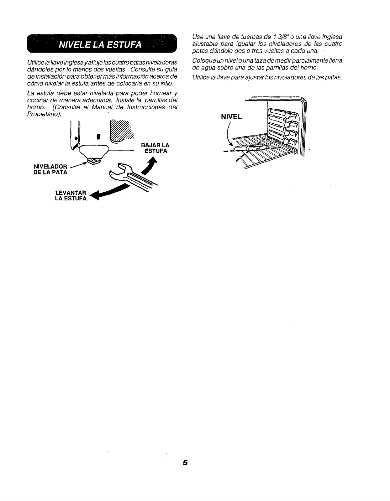
-NIVELE
LA
ESTUFA
Utilice
la
Nave
inglesa
y
atioje
las
cuatro
patas
niveladoras
ddandoles
por
io
menos
dos
vueltas.
Consulte
su
gula
de
instalacion
para
obtener
mas
informacién
acerca
de
cémo
nivelar
la
estufa
antes
de
colocarla
en
su
sitio.
La
estufa
debe
estar
nivelada
para
poder
hornear
y
cocinar
de
manera
adecuada.
Instale
la
parrillas
def
horno.
{Consuite
el
Manuai
de
Instrucciones
del
Propietario).
BAJAR
LA
ESTUFA
NIVELADOR
——~~
3
DE
LA
PATA
SS
LEVANTAR
_
LA
ESTUFA
Use
una
Ilave
de
tuercas
de
1
3/8"
0
una
llave
inglesa
ajustable
para
igualar
los
niveladores
de
las
cuatro
patas
dandole
dos
o
tres
vuelias
a
cada
una.
Coloque
un
nivel
o
una
taza
de
medir
parciaimente
llena
de
agua
sobre
una
de
fas
parrillas
def
horno.
Utilice
la
llave
para
ajustar
los
niveladores
de
/as
patas.

NOTAS

NOTAS

ey
ay
31-10249
Papal
reciclade
229C4053P003-3
8
—Impreso
en
Los
Estados
Unidos
—