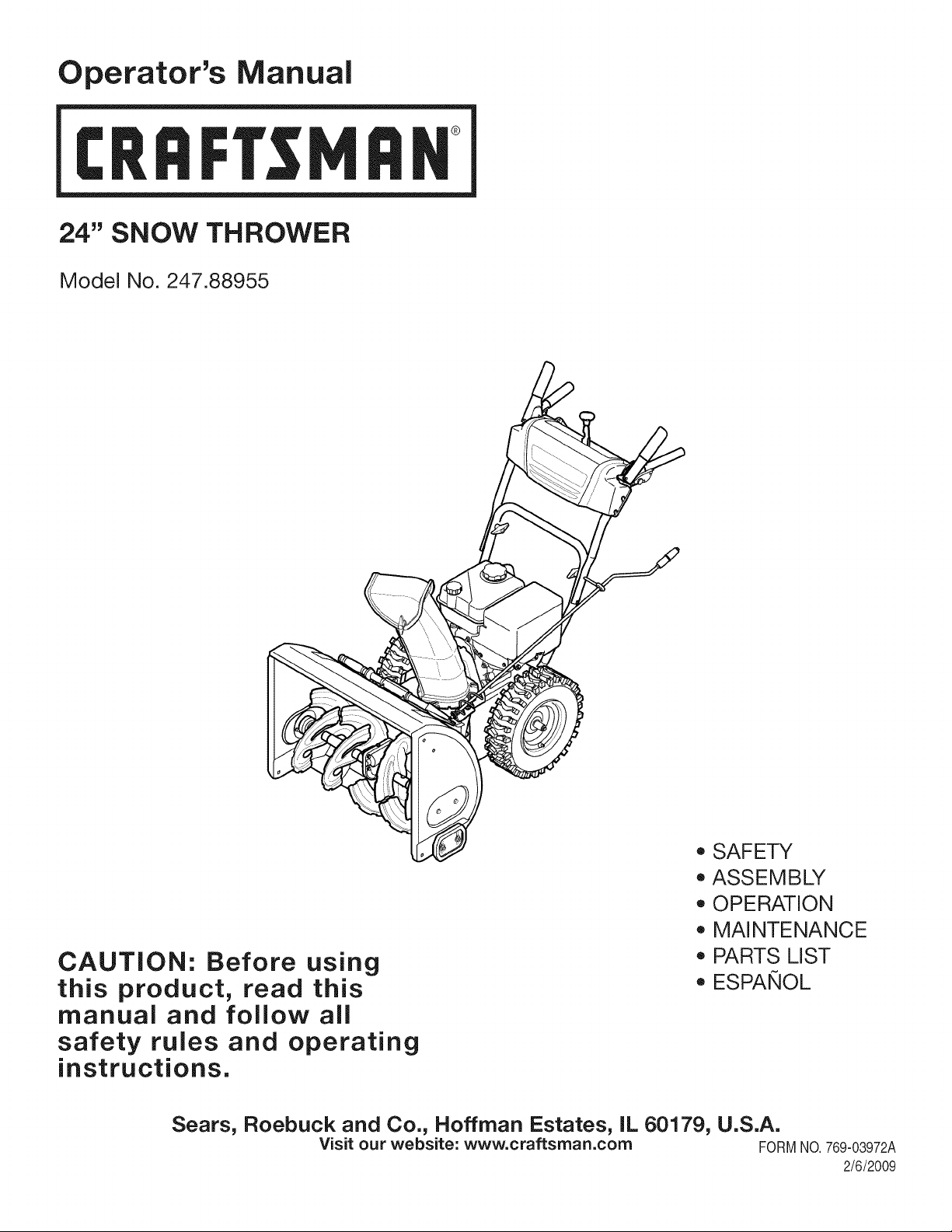
Operator's Manual
CRRFTSMRN
24" SNOW THROWER
Model No. 247.88955
CAUTION: Before using
this product, read this
manual and follow all
safety rules and operating
instructions.
o SAFETY
ASSEMBLY
OPERATION
MAINTENANCE
PARTS LIST
o ESPANOL
Sears, Roebuck and Co., Hoffman Estates, IL 60179, U.S.A.
Visit our website: www.craftsman.com FORM1/0. 769-03972A
2/6/2009
WarrantyStatement.................... Page2
SafeOperationPractices.............. Pages3-6
SafetyLabels......................... Page7
Assembly......................... Pages8-11
Operation........................ Pages12-15
Service&Maintenance.............. Pages16-23
Off-SeasonStorage................... Page24
Troubleshooting...................... Page25
PartsList......................... Pages26-34
RepairProtectionAgreement............ Page38
Espadol............................. Page39
CRAFTSMANLiMiTED WARRANTY
Two Years on Snow Thrower
Whenoperatedand maintainedaccordingto allsuppliedinstructions,if this snowthrowerfailsdue to a defectin materialor workmanshipwithin
twoyearsfromthe dateor purchase,returnit to any authorizedCraftsmandrop-off locationfor free repair. Forthe nearestauthorizedlocation,
call 1-800-4MYHOME.
Thiswarrantyappliesfor only90 daysfromthe dateof purchaseif thissnowthroweris everusedfor commercialor rentalpurposes.
Thiswarranty coversONLYdefects in material andworkmanship. Sears will NOTpay for:
• Expendableitemsthatbecomewornduringnormaluse,includingbutnot limitedto skidshoes,shaveplate,shearpins, sparkplug,air
cleaner,belts,andoil filter.
• Standardmaintenanceservicing,oilchanges,or tune-ups.
• Tire replacementor repaircausedby puncturesfrom outsideobjects,such as nails,thorns,stumps,or glass.
• Tireor wheelreplacementor repairresultingfrom normalwear,accident,or improperoperationor maintenance.
• Repairsnecessarybecauseof operatorabuse, includingbutnot limitedto damagecausedby impactingobjectsthat bendthe frameor
crankshaft,orover-speedingtheengine.
• Repairsnecessarybecauseof operatornegligence,includingbut not limitedto,electricaland mechanicaldamagecausedby improper
storage,failureto usethe propergradeandamountof engineoil, or failureto maintainthe equipmentaccordingto the instructionscontained
inthe operator'smanual.
• Engine(fuelsystem)cleaningor repairscausedbyfuel determinedto becontaminatedoroxidized(stale).In general,fuel shouldbeused
within30 daysof itspurchasedate.
• Normaldeteriorationandwearof the exteriorfinishes,or productlabelreplacement.
Thiswarrantyappliesonly whilethisproductis usedinthe UnitedStates.
Thiswarrantygivesyou specificlegalrights,andyou mayalso haveotherrightswhichvaryfromstateto state.
Sears, Roebuck and Co., NoffmanEstates, IL 60179
EngineOilType: 5W-30
EngineOilCapacity: 20ounces
FuelCapacity: 2.3Quarts
SparkPlug: TorchF6RTC(F6TC)
SparkPlugGap: .020"to .030"
Model Number.................................................................
Serial Number .................................................................
Dateof Purchase.............................................................
Recordthe modelnumber,serialnumber
anddateof purchaseabove
© Sears Brands,LLC
2
Thissymbolpointsout importantsafetyinstructionswhich,if not
followed,couldendangerthepersonalsafetyand/orpropertyof
yourselfandothers. Readandfollowall instructionsin this manual
beforeattemptingto operatethismachine.Failureto complywith
theseinstructionsmayresultin personalinjury.Whenyou seethis
symbol,HEEDITSWARNING!
CALIFORNIA PROPOSITION 65
EngineExhaust,someof itsconstituents,andcertainvehicle
componentscontainoremit chemicalsknownto Stateof California
to cause cancerandbirthdefectsorotherreproductiveharm,
Thismachinewasbuiltto beoperatedaccordingto the safeopera-
tion practicesin this manual.As withanytype of powerequipment,
carelessnessor error on the partof the operatorcan resultin serious
injury.Thismachineis capableof amputatingfingers,hands,toes
andfeet and throwingdebris.Failureto observethe followingsafety
instructionscouldresultin seriousinjuryor death.
Your Responsibility--Restrict the useof this powermachineto
personswho read,understandandfollowthewarningsand instruc-
tionsin thismanualand on the machine,
SAVE THESE INSTRUCTIONS!
TRAiNiNG
• Read,understand,andfollowall instructionson the machineand
in themanual(s)beforeattemptingto assembleandoperate.
Failureto do socan resultin seriousinjuryto the operatorand/
orbystanders.Keepthis manualin a safe placeforfuture and
regularreferenceandfor orderingreplacementparts. Forques-
tionscall, 1-800-659-5917.
• Befamiliarwithall controlsandtheir properoperation.Knowhow
to stop the machineanddisengagethemquickly.
• Neverallowchildrenunder 14 yearsof ageto operatethis
machine.Children14and over shouldreadandunderstandthe
instructionsand safe operationpracticesin this manualand on
the machineand be trainedandsupervisedby an adult.
• Neverallowadultsto operatethis machinewithoutproper
instruction.
• Thrownobjectscan causeseriouspersonalinjury. Planyour
snow-throwingpatternto avoiddischargeof materialtoward
roads,bystandersandthe like.
• Keepbystanders,petsandchildrenat least75 feet from the
machinewhile itisin operation.Stopmachineifanyoneenters
the area.
• Exercisecautionto avoidslippingor falling,especiallywhen
operatingin reverse.
PREPARATION
Thoroughlyinspecttheareawherethe equipmentis to beused.
Removeall doormats,newspapers,sleds,boards,wires and other
foreignobjects,whichcouldbe trippedoverorthrownby the auger/
impeller.
Alwayswear safetyglassesor eyeshieldsduringoperationand
while performingan adjustmentor repairto protectyoureyes.
Thrownobjectswhichricochetcancause seriousinjuryto the
eyes.
Donot operatewithoutwearingadequatewinteroutergarments.
Donot wearjewelry,long scarvesor otherlooseclothing,which
could becomeentangledin movingparts.Wearfootwearwhich
will improvefooting on slipperysurfaces.
Usea groundedthree-wireextensioncordand receptaclefor all
machineswith electricstartengines.
Disengageall controlleversbeforestartingthe engine.
Adjustcollectorhousingheightto cleargravelorcrushedrock
surfaces.
Neverattemptto make anyadjustmentswhileengineis running,
exceptwherespecificallyrecommendedinthe operator'smanual.
Letengineandmachineadjustto outdoortemperaturebefore
startingto clearsnow.
3
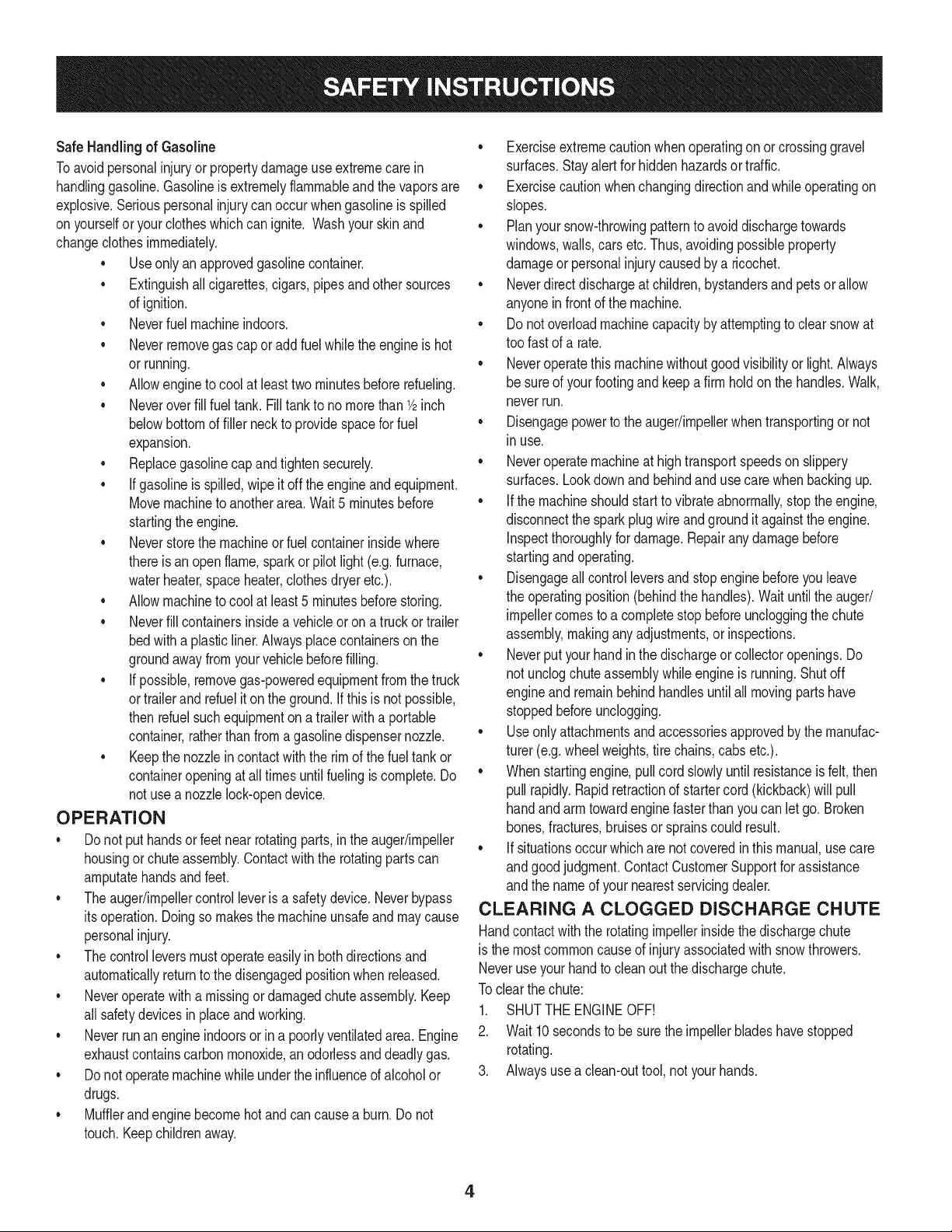
Safe Handling of Gasoline
Toavoidpersonalinjuryor propertydamageuseextremecare in
handlinggasoline.Gasolineis extremelyflammableandthe vaporsare
explosive.Seriouspersonalinjurycan occurwhengasolineis spilled
onyourselfor yourclotheswhichcan ignite.Washyour skin and
changeclothesimmediately.
• Useonly anapprovedgasolinecontainer.
• Extinguishall cigarettes,cigars,pipesand other sources
of ignition.
• Neverfuelmachineindoors.
• Neverremovegas capor addfuel whilethe engineis hot
or running.
• Allowengine to coolat leasttwo minutesbeforerefueling.
• Neveroverfill fueltank. Filltank to no morethan1/2inch
belowbottomof filler neckto providespacefor fuel
expansion.
• Replacegasolinecap andtightensecurely.
• If gasolineis spilled,wipeit offthe engineand equipment.
Movemachineto anotherarea.Wait5 minutesbefore
startingthe engine.
• Neverstorethe machineor fuel containerinsidewhere
thereis an open flame,sparkor pilotlight (e.g.furnace,
waterheater,spaceheater,clothesdryer etc.).
• Allowmachineto cool at least5 minutesbeforestoring.
• Neverfill containersinsidea vehicleor on a truckor trailer
bedwith a plasticliner.Alwaysplacecontainerson the
groundawayfromyourvehiclebeforefilling.
• If possible,removegas-poweredequipmentfrom thetruck
ortrailerand refuelit on the ground.If this is not possible,
then refuelsuchequipmentona trailerwitha portable
container,ratherthan fromagasolinedispensernozzle.
• Keepthe nozzleincontactwiththe rimof the fueltankor
containeropeningat all timesuntil fuelingis complete.Do
notuse a nozzlelock-opendevice.
OPERATION
• Do not puthandsorfeetnear rotatingparts,in the auger/impeller
housingor chuteassembly.Contactwith the rotatingpartscan
amputatehandsand feet.
• Theauger/impellercontrolleveris a safetydevice.Neverbypass
itsoperation.Doingso makesthe machineunsafeand may cause
personalinjury.
• Thecontrol leversmustoperateeasilyin bothdirectionsand
automaticallyreturnto the disengagedpositionwhenreleased.
• Neveroperatewitha missingor damagedchuteassembly.Keep
all safetydevicesin placeandworking.
• Neverrunanengine indoorsor in a poorlyventilatedarea. Engine
exhaustcontainscarbonmonoxide,anodorlessanddeadlygas.
• Do notoperatemachinewhileunder the influenceof alcoholor
drugs.
• Mufflerandenginebecomehotand can causea burn.Do not
touch.Keepchildrenaway.
• Exerciseextremecautionwhenoperatingon or crossinggravel
surfaces.Stayalertfor hiddenhazardsor traffic.
• Exercisecautionwhenchangingdirectionand whileoperatingon
slopes.
• Planyoursnow-throwingpatternto avoiddischargetowards
windows,walls,carsetc. Thus,avoidingpossibleproperty
damageor personalinjurycausedby a ricochet.
• Neverdirect dischargeat children,bystandersand petsor allow
anyoneinfront of the machine.
• Donot overloadmachinecapacityby attemptingto clearsnowat
too fastof a rate.
• Neveroperatethis machinewithoutgoodvisibility or light. Always
be sureof yourfootingand keepa firm hold on the handles.Walk,
neverrun.
• Disengagepowerto theauger/impellerwhentransportingor not
in use.
• Neveroperatemachineat hightransportspeedson slippery
surfaces.Lookdownand behindand usecare whenbackingup.
• If the machineshouldstart to vibrateabnormally,stopthe engine,
disconnectthe spark plugwire andgroundit againstthe engine.
Inspectthoroughlyfor damage.Repairanydamagebefore
startingandoperating.
• Disengageall controlleversand stop enginebeforeyouleave
the operatingposition(behindthe handles).Wait untilthe auger/
impellercomesto a completestop beforeuncloggingthechute
assembly,makingany adjustments,or inspections.
• Neverput yourhandinthe dischargeor collectoropenings.Do
not unclogchuteassemblywhileengineis running.Shutoff
engineand remainbehindhandlesuntilall movingparts have
stoppedbeforeunclogging.
• Useonly attachmentsandaccessoriesapprovedby the manufac-
turer (e.g.wheelweights,tire chains,cabsetc.).
• Whenstartingengine,pull cord slowlyuntilresistanceis felt, then
pull rapidly.Rapidretractionof startercord(kickback)will pull
handand armtowardenginefasterthan youcan let go. Broken
bones,fractures,bruisesor sprainscould result.
• If situationsoccur whichare notcoveredin this manual,use care
andgood judgment.ContactCustomerSupportfor assistance
andthe nameof your nearestservicingdealer.
CLEARING A CLOGGED DISCHARGE CHUTE
Handcontactwiththe rotatingimpellerinsidethe dischargechute
is the mostcommoncauseof injuryassociatedwithsnowthrowers.
Neveruse yourhand to cleanout thedischargechute.
Toclear thechute:
1. SHUTTHEENGINEOFF!
2. Wait 10secondsto be surethe impellerbladeshavestopped
rotating.
3. Alwaysusea clean-outtool, not yourhands.
4
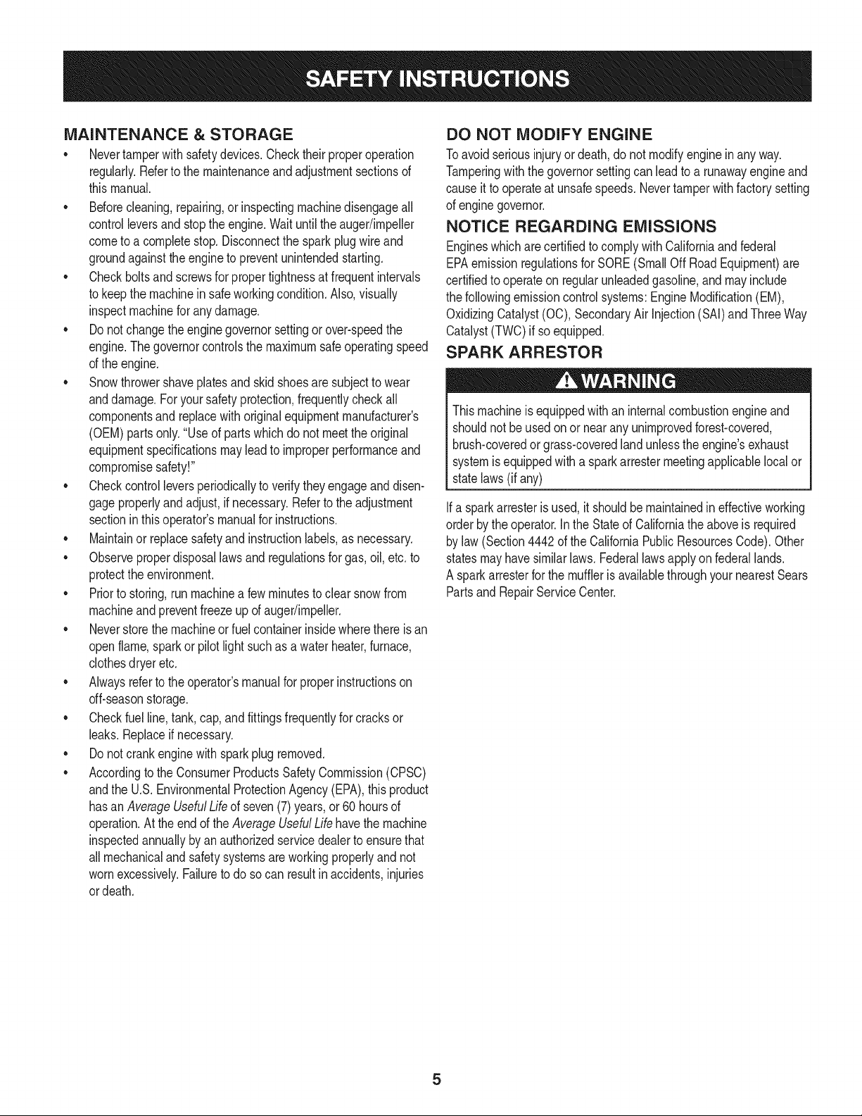
MAINTENANCE & STORAGE
• Nevertamperwith safetydevices.Checktheirproperoperation
regularly.Referto the maintenanceandadjustmentsectionsof
thismanual.
• Beforecleaning,repairing,or inspectingmachinedisengageall
controlleversandstop the engine.Waituntilthe auger/impeller
cometo a completestop.Disconnectthe sparkplugwireand
groundagainsttheengineto preventunintendedstarting.
Checkboltsand screwsfor propertightnessat frequentintervals
to keepthe machineinsafe workingcondition.Also, visually
inspectmachinefor anydamage.
Do notchangetheenginegovernorsettingor over-speedthe
engine.Thegovernorcontrolsthe maximumsafeoperatingspeed
of the engine.
Snowthrowershaveplatesand skidshoesare subjectto wear
anddamage.Foryoursafetyprotection,frequentlycheckall
componentsand replacewithoriginalequipmentmanufacturer's
(OEM)partsonly."Useof parts whichdo not meetthe original
equipmentspecificationsmayleadto improperperformanceand
compromisesafety!"
Checkcontrolleversperiodicallyto verifythey engageanddisen-
gageproperlyand adjust,if necessary.Referto the adjustment
sectioninthisoperator'smanualfor instructions.
Maintainor replacesafetyandinstructionlabels,as necessary.
• Observeproperdisposallawsand regulationsfor gas,oil,etc. to
protectthe environment.
Priorto storing,runmachinea few minutestoclear snowfrom
machineand preventfreezeupof auger/impeller.
Neverstorethe machineorfuel containerinsidewherethereisan
openflame,spark or pilot lightsuchas a waterheater,furnace,
clothesdryer etc.
Alwaysreferto the operator'smanualfor properinstructionson
off-seasonstorage.
Checkfuelline,tank, cap,andfittingsfrequentlyfor cracksor
leaks.Replaceif necessary.
Do notcrank enginewithsparkplugremoved.
Accordingto the ConsumerProductsSafetyCommission(CPSC)
andthe U.S.EnvironmentalProtectionAgency(EPA),this product
hasan AverageUsefulLifeof seven(7) years,or 60 hoursof
operation.At the endof theAverageUsefulLifehavethe machine
inspectedannuallybyan authorizedservicedealer to ensurethat
allmechanicalandsafetysystemsare workingproperlyand not
wornexcessively.Failureto do so can resultinaccidents,injuries
ordeath.
DO NOT MODIFY ENGINE
Toavoidseriousinjuryor death,do not modifyengineinany way.
Tamperingwiththe governorsettingcanleadto a runawayengineand
causeit to operateat unsafespeeds.Nevertamperwithfactory setting
of engine governor.
NOTICE REGARDING EMISSIONS
Engineswhich are certifiedtocomplywith Californiaand federal
EPAemissionregulationsfor SORE(SmallOff RoadEquipment)are
certifiedto operateon regularunleadedgasoline,and mayinclude
the followingemissioncontrol systems:EngineModification(EM),
OxidizingCatalyst(OC),SecondaryAirInjection(SAI)and ThreeWay
Catalyst(TWO)if so equipped.
SPARK ARRESTOR
Thismachineisequippedwithan internalcombustionengineand
shouldnotbe usedonor nearany unimprovedforest-covered,
brush-coveredorgrass-coveredlandunlessthe engine'sexhaust
systemisequippedwitha sparkarrestermeetingapplicablelocalor
statelaws(if any)
Ifa sparkattesteris used,it shouldbe maintainedin effectiveworking
orderby theoperator.Inthe State of Californiathe aboveis required
bylaw (Section4442 of the CaliforniaPublicResourcesCode). Other
statesmayhavesimilarlaws. Federallawsapplyonfederallands.
A sparkarresterfor the muffleris availablethroughyournearestSears
PartsandRepairServiceCenter.
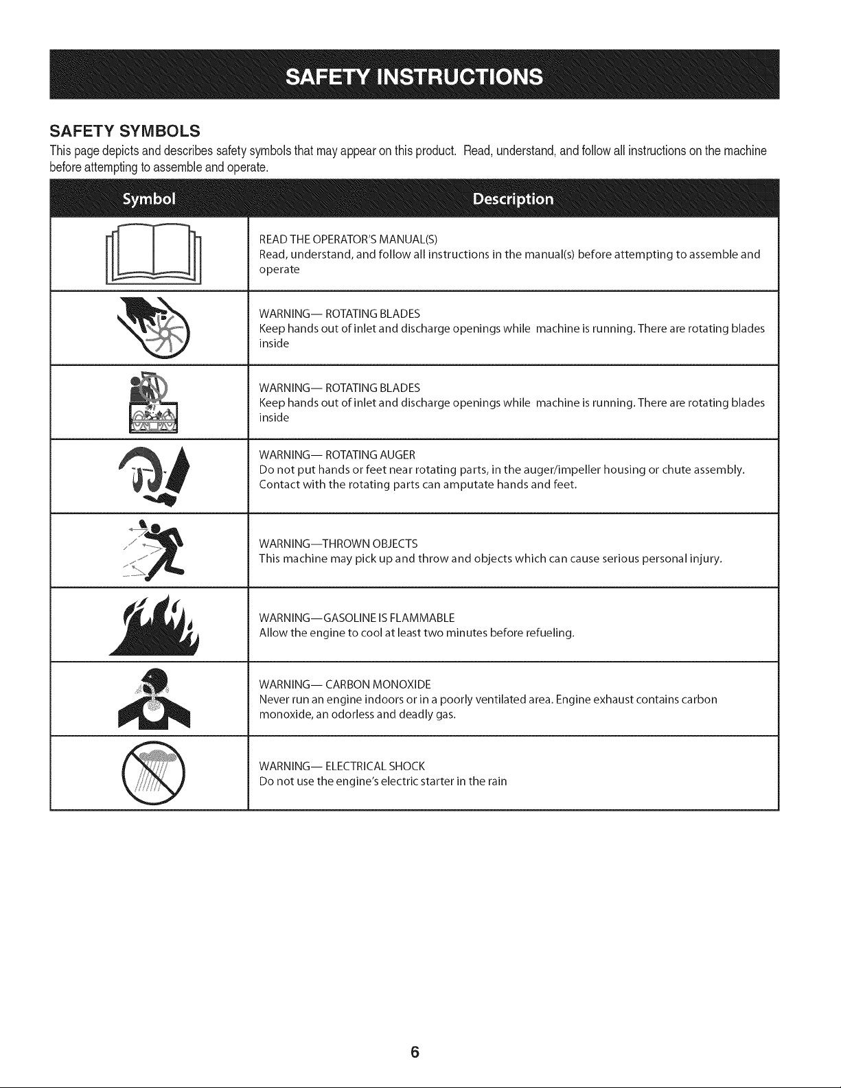
SAFETY SYMBOLS
Thispagedepictsanddescribessafetysymbolsthat mayappear on this product. Read,understand,andfollowall instructionson the machine
beforeattemptingto assembleandoperate.
i
i
READ THE OPERATOR'S MANUAL(S)
Read, understand, and follow all instructions in the manual(s) before attempting to assemble and
operate
WARNING-- ROTATING BLADES
Keep hands out of inlet and discharge openings while machine is running. There are rotating blades
inside
WARNING-- ROTATING BLADES
Keep hands out of inlet and discharge openings while machine is running. There are rotating blades
inside
WARNING-- ROTATING AUGER
Do not put hands or feet near rotating parts, in the auger/impeller housing or chute assembly.
Contact with the rotating parts can amputate hands and feet.
WARNING--THROWN OBJECTS
This machine may pick up and throw and objects which can cause serious personal injury.
WARNING--GASOLINE IS FLAMMABLE
Allow the engine to cool at least two minutes before refueling.
WARNING-- CARBON MONOXIDE
Never run an engine indoors or in a poorly ventilated area. Engine exhaust contains carbon
monoxide, an odorless and deadly gas.
WARNING-- ELECTRICAL SHOCK
Do not use the engine's electric starter in the rain
6
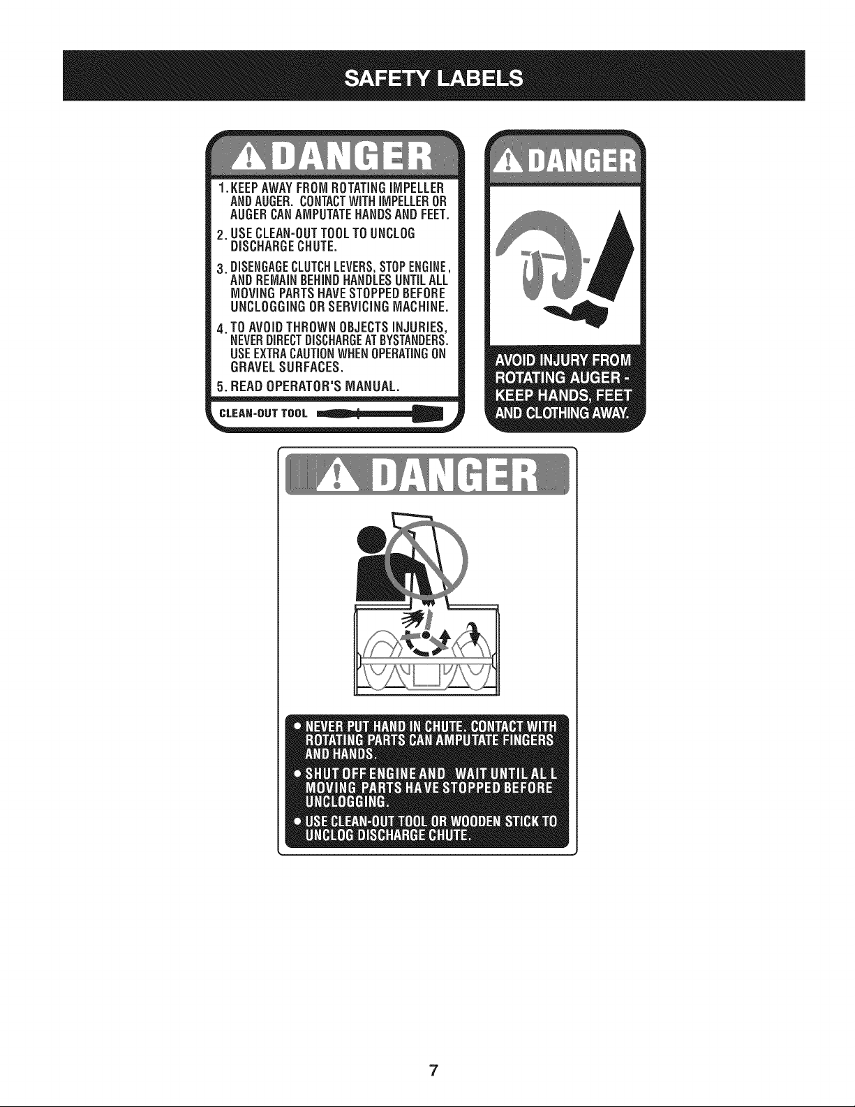
1.KEEPAWAYFROMROTATINGiMPELLER
ANDAUGER,CONTACTWiTHiMPELLEROR
AUGERCANAMPUTATEHANDSANDFEET.
2. USECLEAN-OUTTOOLTOUNCLOG
DISCHARGECHUTE.
3.DISENGAGECLUTCHLEVERS,STOPENGINE,
AND REMAINBEHINDHANDLESUNTILALL
MOVING PARTSHAVE STOPPEDBEFORE
UNCLOGGING OR SERViCiNGMACHINE.
TO AVOIDTHROWN OBJECTSiNJURiES,
NEVERDIRECTDISCHARGEATBYSTANDERS.
USEEXTRACAUTIONWHEN OPERATINGON
GRAVEL SURFACES.
5.BEAD OPERATOR'S MANUAL.
CLEAN-OUT TOOL
7
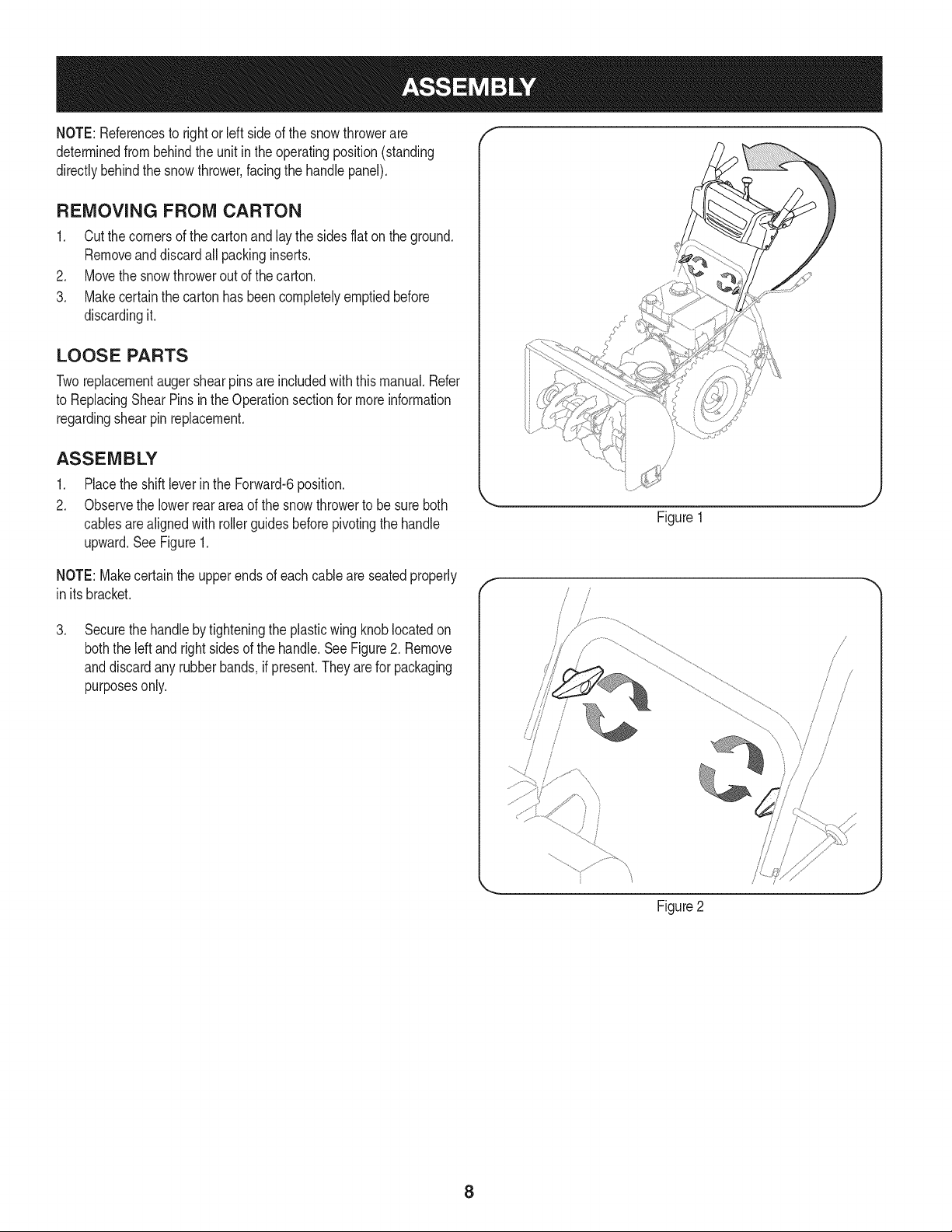
NOTE:Referencesto rightorleft sideof the snowthrowerare
determinedfrombehindthe unit in the operatingposition(standing
directlybehindthe snow thrower,facingthe handlepanel).
REMOVING FROM CARTON
1. Cut the cornersof thecarton and lay the sidesflaton the ground.
Removeand discard all packinginserts.
2. Movethe snowthrowerout of thecarton.
3. Makecertainthe cartonhas beencompletelyemptiedbefore
discardingit.
LOOSE PARTS
Tworeplacementaugershearpinsare includedwiththis manual.Refer
to ReplacingShear Pinsin the Operationsectionfor moreinformation
regardingshearpin replacement.
ASSEMBLY
1. Placethe shiftleverin the Forward-6position.
2. Observethe lowerreararea of the snowthrowerto besure both
cablesarealignedwith rollerguidesbeforepivotingthe handle
upward.See Figure1.
Figure1
NOTE:Makecertainthe upperends of eachcableare seatedproperly
in itsbracket.
.
Securethehandlebytighteningthe plasticwing knoblocatedon
boththe left and rightsides of the handle.SeeFigure2. Remove
anddiscardany rubberbands,if present.They are for packaging
purposesonly.
f
!
/
/
/
Figure2
8
.
5.
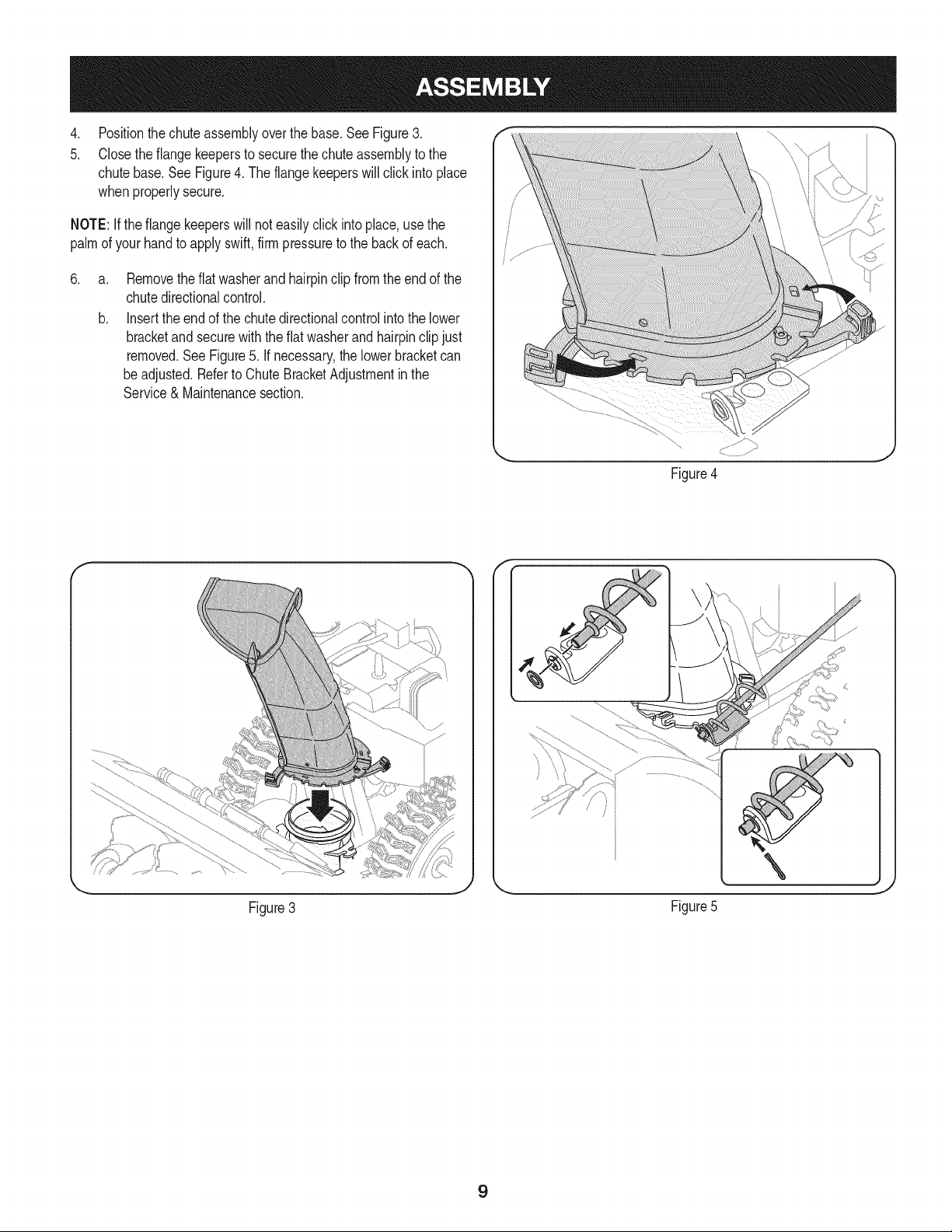
Positionthechuteassemblyoverthe base.See Figure3.
Closethe flangekeepersto securethechuteassemblyto the
chutebase.See Figure4. The flangekeeperswill click intoplace
whenproperlysecure.
NOTE:Ifthe flangekeeperswill noteasilyclickinto place,usethe
palmof yourhand to applyswift,firmpressureto the backof each.
.
a.
b.
Removetheflatwasherand hairpinclip fromthe end of the
chutedirectionalcontrol.
Insertthe end of the chutedirectionalcontrolinto the lower
bracketandsecurewith the flatwasherandhairpinclipjust
removed.See Figure5. If necessary,the lowerbracketcan
beadjusted.Referto ChuteBracketAdjustmentin the
Service& Maintenancesection.
Figure4
f F
Figure3
\
J
Figure5
9
SET-UP
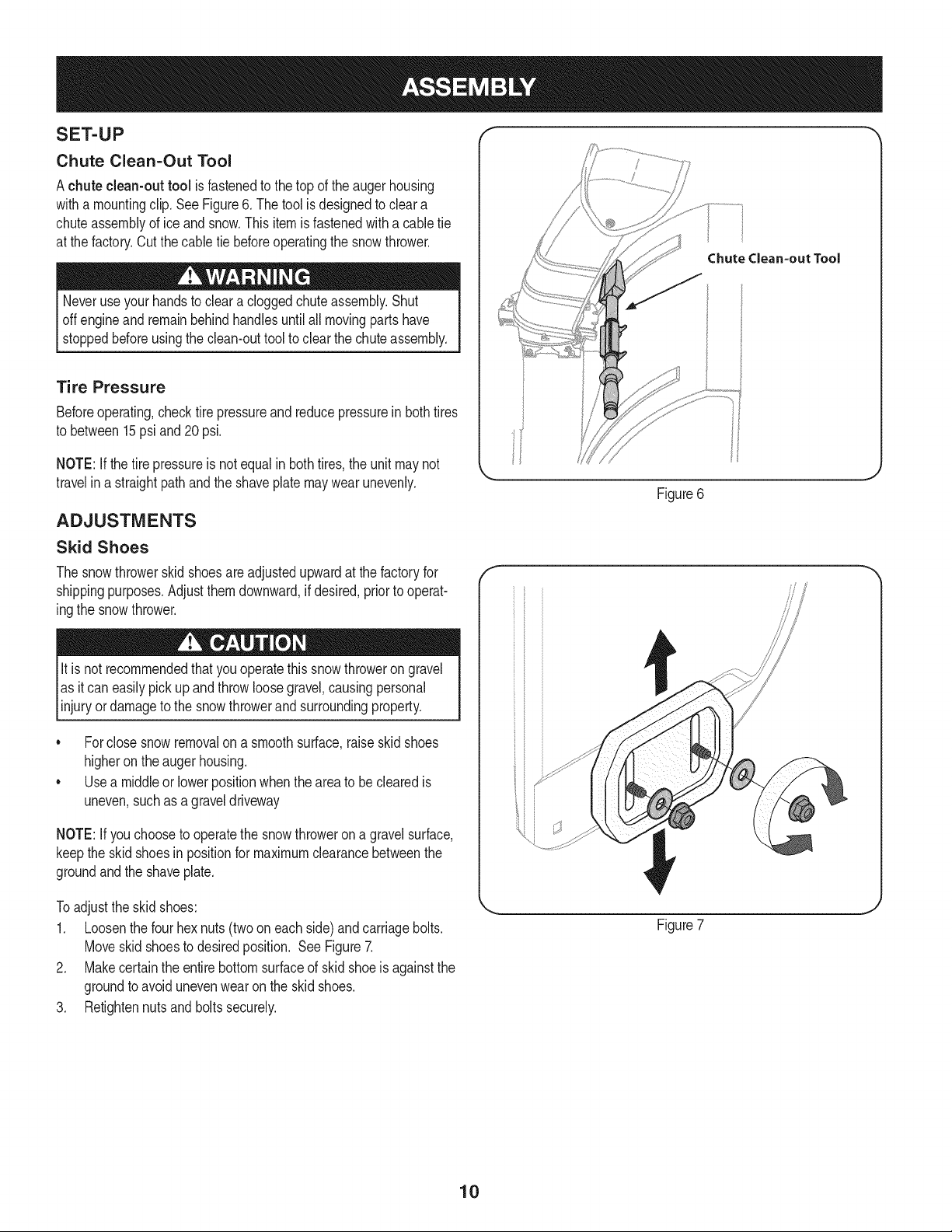
Chute Clean-Out Tool
Achute clean-out tool is fastenedto the top of the augerhousing
witha mountingclip.SeeFigure6. The tool is designedto cleara
chuteassemblyof ice and snow.This item is fastenedwitha cabletie
at the factory.Cut thecable tie beforeoperatingthe snowthrower.
Neveruseyour handsto cleara cloggedchuteassembly.Shut
offengineand remainbehind handlesuntilall movingpartshave
stoppedbeforeusingthe clean-outtool to clear thechute assembly.
Tire Pressure
Beforeoperating,checktire pressureand reducepressureinbothtires
to between15psiand20 psi.
NOTE:If thetire pressureis notequal in bothtires,the unit maynot
travelin a straightpathandthe shaveplatemaywearunevenly.
ADJUSTMENTS
Skid Shoes
The snowthrowerskid shoesareadjustedupwardat thefactory for
shippingpurposes.Adjustthemdownward,if desired,priorto operat-
ingthe snowthrower.
It is not recommendedthatyouoperatethis snowthroweron gravel
as it can easilypick up andthrowloosegravel,causingpersonal
njuryordamageto the snowthrowerand surroundng property.
• Forclosesnowremovalona smoothsurface,raiseskidshoes
higheronthe augerhousing.
• Usea middleor lowerpositionwhentheareato be clearedis
uneven,suchas a graveldriveway
NOTE:If youchooseto operatethe snowthroweron a gravelsurface,
keepthe skid shoesin positionfor maximumclearancebetweenthe
groundandthe shaveplate.
ChuteClean-outTool
Figure6
f
Toadjustthe skid shoes:
1. Loosenthe four hexnuts (two oneach side)and carriagebolts.
Moveskidshoesto desiredposition. SeeFigure7.
2. Makecertainthe entirebottomsurfaceof skidshoeis againstthe
groundto avoidunevenwearonthe skid shoes.
3. Retightennutsand boltssecurely.
Figure7
10
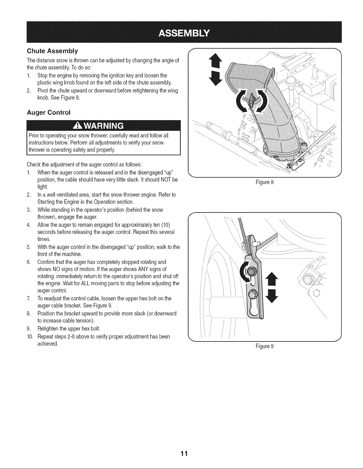
Chute Assembly
Thedistancesnowis throwncan beadjustedby changingthe angleof
the chuteassembly.Todo so:
1. Stopthe engineby removingthe ignitionkeyandloosenthe
plasticwingknobfoundonthe left sideof the chuteassembly.
2. Pivotthe chuteupwardordownwardbeforeretighteningthewing
knob.See Figure8.
Auger Control
Priorto operatingyour snowthrower,carefullyreadand followall
instructionsbelow. Performall adjustmentsto verifyyour snow
throweris operatingsafelyandproperly.
Checktheadjustmentof the augercontrolas follows:
1. Whentheaugercontrolis releasedandin the disengaged"up"
position,the cableshouldhavevery littleslack.ItshouldNOTbe
tight.
2. In a well-ventilatedarea,start the snowthrowerengine.Referto
Startingthe Engineinthe Operationsection.
3. Whilestandingin the operator'sposition(behindthe snow
thrower),engagethe auger.
4. Allowtheauger to remainengagedfor approximatelyten (10)
secondsbeforereleasingthe augercontrol.Repeatthisseveral
times.
5. With theauger controlin thedisengaged"up" position,walkto the
frontof the machine.
6. Confirmthat the augerhas completelystoppedrotatingand
showsNOsignsof motion.If the augershowsANYsignsof
rotating,immediatelyreturnto the operator'spositionandshutoff
the engine.Waitfor ALL movingparts to stopbeforeadjustingthe
augercontrol.
7. Toreadjustthecontrolcable, loosentheupper hexbolt on the
augercablebracket.SeeFigure9.
8. Positionthe bracketupwardto providemoreslack(or downward
to increasecabletension).
9. Retightenthe upperhex bolt.
10. Repeatsteps2-6 aboveto verifyproperadjustmenthasbeen
achieved.
Figure8
Figure9
11
f
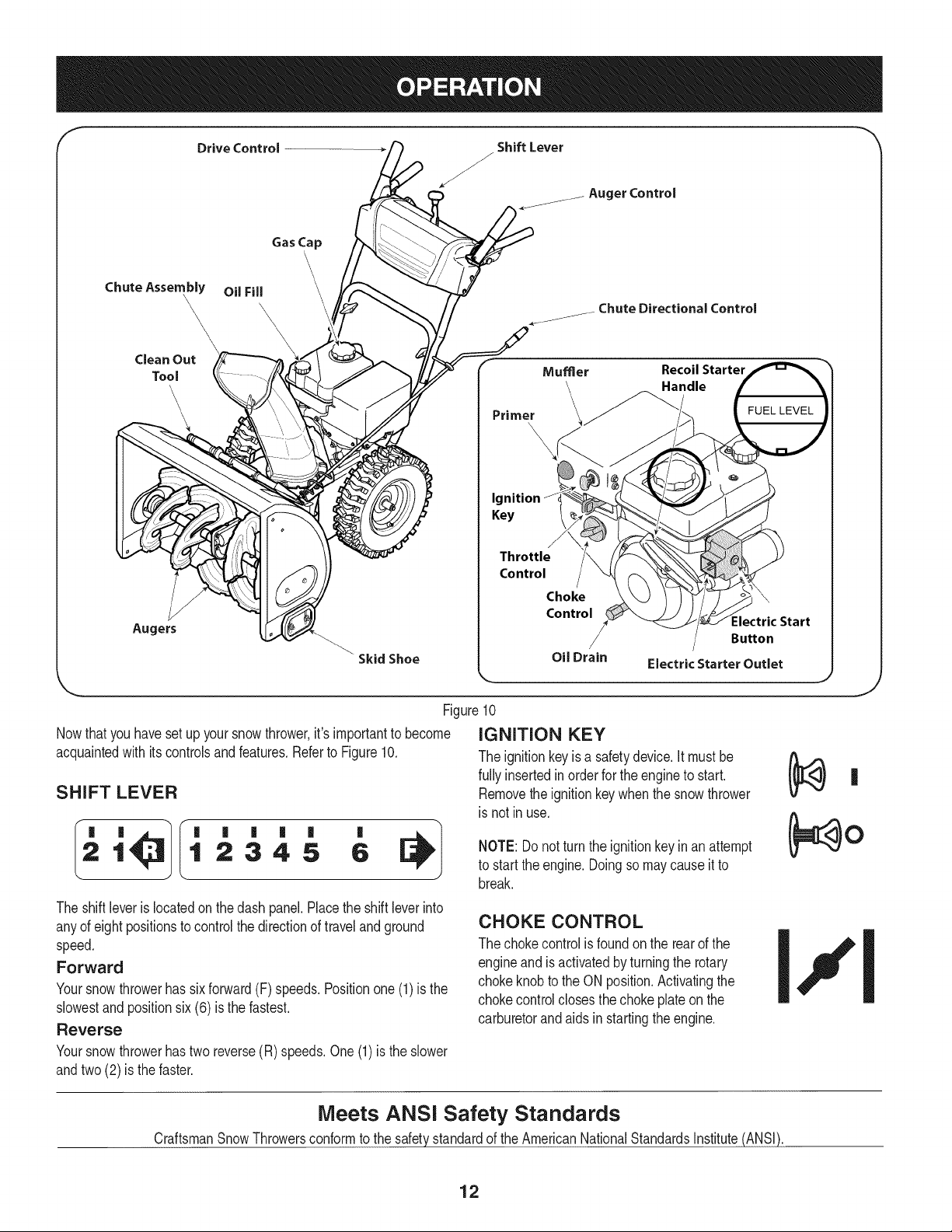
Drive Control
ShiftLever
/
J
Auger Control
Gas Cap
Chute Assembly OilFill
\ \,
\
\
_ ChuteDirectionalControl
Clean Out
Tool
\
Augers
SkidShoe
Primer
Mumer Recoil Starter
andle
Ignition
Key
Throttle
Control
Choke
Control
:lectric Start
Button
Oil Drain
Electric Starter Outlet
Figure10
Nowthat youhavesetup yoursnowthrower,it's importantto become
acquaintedwith itscontrolsand features.Referto Figure10.
SHIFT LEVER
1 2345 6
The shiftleveris locatedonthe dash panel.Placethe shift leverinto
anyof eight positionsto controlthe directionof travelandground
speed.
Forward
Yoursnowthrowerhas six forward(F) speeds.Positionone(1)is the
slowestandpositionsix (6) is the fastest.
Reverse
Yoursnowthrowerhastwo reverse(R) speeds.One (1) is the slower
andtwo (2) is the faster.
IGNITION KEY
The ignitionkeyis a safetydevice.It mustbe
fullyinsertedinorderfor the engineto start.
Removethe ignitionkeywhenthe snowthrower
is not inuse.
NOTE: Donot turnthe ignitionkey inan attempt
to startthe engine.Doingso may causeit to
break.
CHOKE CONTROL
The chokecontrolis foundon the rearof the
engineand isactivatedby turningthe rotary
chokeknobto the ON position.Activatingthe
chokecontrolclosesthe chokeplateonthe
carburetorandaids in startingthe engine.
J
Meets ANSi Safety Standards
CraftsmanSnowThrowersconformto the safetystandardof the AmericanNationalStandardsInstitute(ANSi).
12
THROTTLE CONTROL
The throttle control is located on the rear of the engine. It regulates the
speed of the engine and willshut off the engine when moved into the
STOP position.
PRIMER I _TY-"-L
Depressingthe primerforcesfuel directlyintothe
engine'scarburetorto aid in cold-weatherstarting.
RECOIL STARTER HANDLE
Thishandleis usedto manuallystartthe engine.
ELECTRIC STARTER BUTTON
Pressingthe electricstarterbuttonengagesthe engine'selectric
starterwhenpluggedintoa 120Vpowersource.
ELECTRIC STARTER OUTLET
Requiresthe useof a three-prongoutdoorextensioncord(included)
anda 120Vpowersource/walloutlet.
OIL FILL
Engineoil levelcan becheckedand oiladdedthroughtheoil fill.
GAS CAP
Unthreadthe gascap to addgasolineto the fuel tank.
AUGERS
Whenengaged,the augersrotateanddrawsnow intothe auger
housing.
CHUTE ASSEMBLY
Snowdrawninto theaugerhousingis dischargedout the chute
assembly.
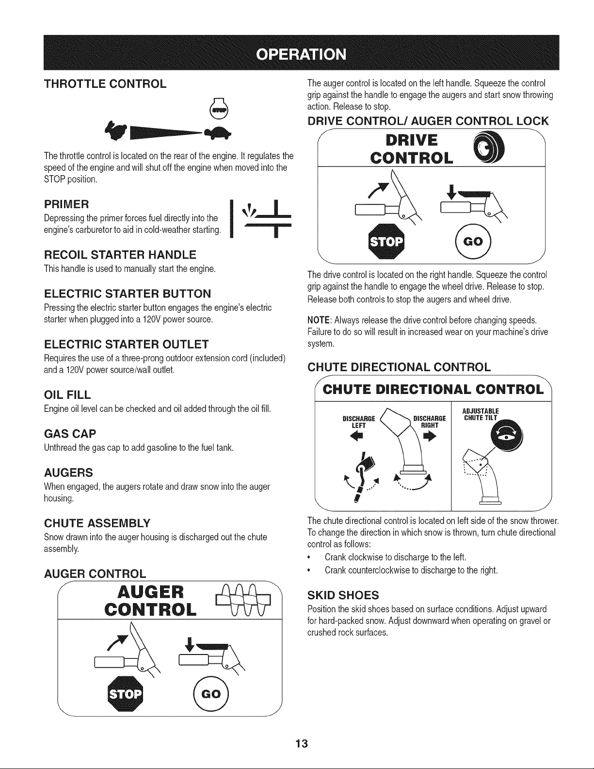
AUGER CONTROL
J AUGER
CONTROL
The augercontrolis locatedon the lefthandle.Squeezethe control
gripagainstthe handleto engagethe augersand startsnowthrowing
action.Releaseto stop.
DRIVE CONTROL/AUGER CONTROL LOCK
J DRIVE
CONTROL
The drivecontrolis locatedon the righthandle.Squeezethe control
gripagainstthe handleto engagethe wheeldrive.Releaseto stop.
Releasebothcontrolsto stopthe augersandwheeldrive.
NOTE:Alwaysreleasethedrivecontrolbeforechangingspeeds.
Failureto do so will result in increasedwearon yourmachine'sdrive
system.
CHUTE DIRECTIONAL CONTROL
/_CCHUTE DIRECTIONAL CONTROL
ADJUSTABLE
CHUTETILT
DISCHARGE DISCHARGE
LEFT
,....
#
\ J
The chutedirectionalcontrol is locatedonleft sideof the snowthrower.
Tochangethe directioninwhichsnowis thrown,turnchutedirectional
controlas follows:
* Crankclockwiseto dischargeto the left.
* Crankcounterclockwiseto dischargeto the right.
SKID SHOES
Positionthe skid shoesbasedonsurfaceconditions.Adjustupward
for hard-packedsnow.Adjustdownwardwhenoperatingon gravelor
crushedrocksurfaces.
13
CLEAN-OUT TOOL
Neveruse yourhandsto cleara cloggedchuteassembly.Shut
off engineandremainbehindhandlesuntilall movingpartshave
stoppedbeforeusingthe clean-outtoolto clear thechuteassembly.
Thechuteclean-outtool is convenientlyfastenedto the rear of the
augerhousingwith a mountingclip. Shouldsnowandice become
lodgedin thechuteassemblyduringoperation,proceedas followsto
safelycleanthechuteassemblyandchute opening:
1. Releaseboththe AugerControlandthe DriveControl.
2. Stopthe engineby removingthe ignitionkey.
3. Removethe clean-outtoolfromthe clip whichsecuresit to the
rearof the augerhousing.
4. Use the shovel-shapedend of theclean-outtool to dislodgeand
scoopany snowand icewhich hasformedin andnearthechute
assembly.
5. Refastenthe clean-outtool to the mountingclip onthe rearof
theaugerhousing,reinsertthe ignitionkeyandstartthe snow
thrower'sengine.
6. Whilestandingin the operator'sposition(behindthesnow
thrower),engagethe augercontrolfora fewsecondsto clear any
remainingsnowandice fromthechuteassembly.
BEFORE STARTING ENGINE
Read,understand,and followall instructionsandwarningson the
machineand inthismanualbeforeoperating.
Oil
The unitwas shippedwithoil in the engine.Checkoil levelbeforeeach
operationto ensureadequateoilin the engine.Forfurther instructions,
referto the stepsonpage 16.
NOTE:Besureto checkthe engineon a levelsurfacewith the engine
stopped.
1. Removethe oil fillercap/dipstickandwipethe dipstickclean.
2. Insertthe cap/dipstickintotheoil filler neck,butdo not screwit in.
3. Removethe oil fillercap/dipstick.Ifthe levelis low,slowlyadd
oil (5%30, witha minimumclassificationof SF/SG)untiloil level
registersbetweenhigh(H) and low(L).
NOTE:Do notoverfill.Overfillingwith oil mayresult in enginesmoking,
hardstartingor spark plugfouling.
4. Replaceand tighten cap/dipstickfirmlybeforestartingengine.
Gasoline
Useautomotivegasoline(unleadedor low leadedto minimizecombus-
tionchamberdeposits)with a minimumof 87 octane.Gasolinewith
upto 10%ethanolor 15%MTBE(MethylTertiaryButylEther)canbe
used.Neverusean oil/gasolinemixtureor dirty gasoline.Avoidgetting
dirt,dust,or waterin thefuel tank. DO NOTuse E85gasoline.
• Refuelin a well-ventilatedarea with the enginestopped.Do not
smokeorallowflamesor sparksin the areawherethe engineis
refueledor wheregasolineis stored.
• Donot overfillthe fueltank.After refueling,makesurethe tank
cap is closedproperlyand securely.
• Be carefulnotto spillfuel whenrefueling.Spilledfuel or fuel vapor
mayignite.If any fuelis spilled,makesurethe area is dry before
startingthe engine.
• Avoidrepeatedor prolongedcontact with skinor breathingof
)or.
Useextremecarewhen handlinggasoline.Gasolineis extremely
flammableandthevaporsare explosive.Never fuelthe machine
indoorsorwhilethe engine is hotor running.Extinguishcigarettes,
cigars,pipesandothersourcesof ignition.
1. Cleanaroundfuel fill beforeremovingcap to fuel.
2. A fuel levelindicatoris locatedin the fueltank. Fill tankuntilfuel
reachesthe fuel levelindictor.SeeFigure10inset.Be careful not
to overfill.
STARTING THE ENGINE
Alwayskeep handsandfeetclearof movingparts. Donot usea
pressurizedstartingfluid.Vaporsare flammable.
NOTE:Allowthe engineto warmup for a fewminutesafter starting.
The enginewill notdevelopfull poweruntilit reachesoperating
temperatures.
1. Makecertainboththe augercontroland drivecontrolare in the
disengaged(released)position.
2. Insertignitionkey into slot.Makesure it snapsinto place.Do not
attemptto turn the key.
NOTE: Theenginecannotstartwithoutthe keyis fully insertedintothe
ignitionswitch.
Electric Starter
The optionalelectricstarteris equippedwitha groundedthree-wire
powercordand plug,andis designedto operateon 120volt AC
householdcurrent.It mustbe usedwith a properlygroundedthree-
prongreceptacleat all timesto avoidthe possibilityof electricshock.
Followall instructionscarefullyprior to operatingthe electricstarter.
DONOTuseelectricstarterinthe rain.
Determinethat yourhome'swiringis a three-wiregroundedsystem.
Aska licensedelectricianif you are notcertain.
Ifyou havea groundedthree-prongreceptacle,proceedas follows.
Ifyou do not havethe properhousewiring,DONOTusethe electric
starterunderanyconditions.
1. Plugthe extensioncord intothe outlet locatedon the engine's
surface.Plugthe otherendof extensioncord intoa three-prong
120-volt,grounded,AC outletina well-ventilatedarea.
14
2. Movethrottlecontrolto FAST(rabbit)_ position.
3. Movechoketo the ON position I,"1(c denginestart).If
engineis warm,placechokein RUNposition.
4. Pushprimerthree to five (3-5) times,makingsureto covervent
holewhenpushing.If engineis warm,pushprimeronlyonce.
Alwayscoverventhole whenpushing.Cool weathermayrequire
primingto berepeated.
5. Pushstarterbuttonto start engine.Oncethe enginestarts,im-
mediatelyreleasestarterbutton.Electricstarteris equippedwith
thermaloverloadprotection;systemwill temporarilyshut-downto
allowstarterto cool if electricstarterbecomesoverloaded.
TO ENGAGE DRIVE
1. Withthe throttlecontrolinthe Fast(rabbit) '_ position,move
shiftleverintooneof thesix forward(F) positionsor two reverse
(R) positions.Selecta speedappropriatefor the snowconditions
anda paceyou'recomfortablewith.
NOTE: When selectinga DriveSpeed,use the slowerspeedsuntil
you are comfortableand familiarwiththe operationof the snow
thrower.
2. Squeezethe drivecontrolagainstthe handleandthe snow
throwerwill move.Releaseit anddrive motionwill stop.
6. As theenginewarms,slowlyrotatethe chokecontrol to RUN
position.If the enginefalters,restartengineandrunwithchoke
at half-chokepositionfor a shortperiodof time,andthen slowly
rotatethe chokeinto RUNposition.
7. After engineis running,disconnectpowercordfromelectric
starter.Whendisconnecting,alwaysunplugthe endat the wall
outletbeforeunpluggingtheoppositeendfrom the engine.
RecoiJ Starter
NOTE:NEVERrepositionthe shiftlever(changespeedsor direction
of travel)withoutfirst releasingthe drivecontrolandbringingthe snow
throwerto a completestop.Doingsowill resultin prematurewearto
the snow thrower'sdrivesystem.
TO ENGAGE AUGERS
1. Toengagethe augersandstartthrowingsnow,squeezethe
augercontrolagainstthe lefthandle.Releaseto stop theaugers.
Do notpull the starterhandlewhilethe enginerunning.
1. Movethrottlecontrolto FAST(rabbit)_ position.
2. Movechoketo the ON position I,,_q (coldenginestart).If
engineis warm,placechokein RUNposition.
3. Pushprimerthree to five (3-5) times,makingsureto covervent
holewhenpushing.If engineis warm,pushprimeronlyonce.
Alwayscoverventhole whenpushing.Cool weathermayrequire
primingto berepeated.
4. Pull gentlyon the starterhandleuntil it beginsto resist,then
pullquicklyandforcefullyto overcomethe compression.Do
not releasethe handleand allowit to snapback.Returnrope
SLOWLYto original position.If required,repeatthisstep.
5. As theenginewarms,slowlyrotatethe chokecontrol to RUN
position.If the enginefalters,restartengineandrunwithchoke
at half-chokepositionfor a shortperiodof time,andthen slowly
rotatethe chokeinto RUNposition.
Toavoid unsupervisedengineoperation,neverleavethemachine
unattendedwith the enginerunning.Turnthe engineoff after use and
removeignitionkey.
STOPPING THE ENGINE
Afteryouhavefinishedsnow-throwing,run enginefora few minutes
beforestoppingto help dry offany moistureonthe engine.
1. Movethrottlecontrolto STOP_ position.
2. Removetheignitionkey.Removingthe keywill reducethe pos-
sibilityof unauthorizedstartingof theenginewhileequipmentis
not in use. Keepthe key in a safeplace.The enginecannotstart
withoutthe ignitionkey.
3. Wipeany moistureawayfrom the controlson theengine.
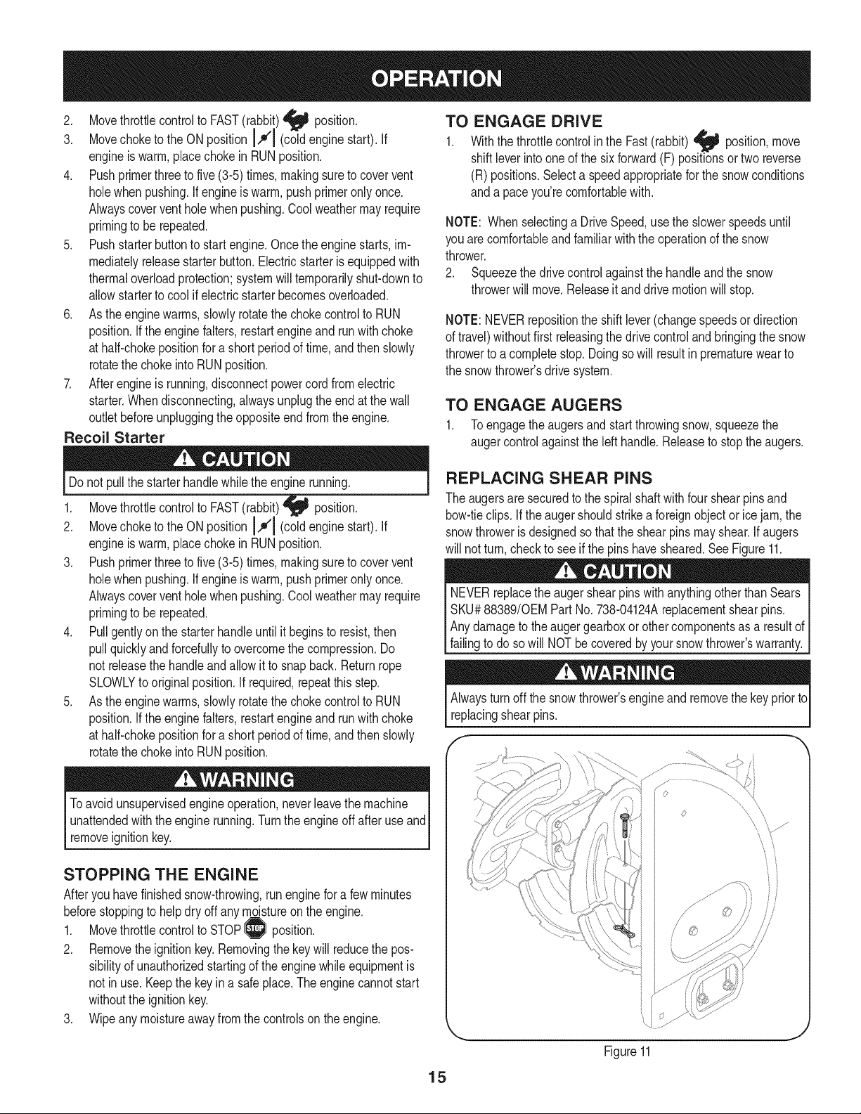
REPLACING SHEAR PINS
The augersare securedto the spiralshaftwith four shearpinsand
bow-tieclips. If the augershouldstrikea foreignobject or icejam,the
snowthroweris designedso thatthe shearpins mayshear.If augers
will not turn,checkto seeif the pinshavesheared.SeeFigure11.
NEVERreplacethe augershearpinswithanythingotherthanSears
SKU#88389/0EMPart No.738-04124Areplacementshearpins.
Anydamageto the augergearboxor othercomponentsas a resultof
[fa ngto do so w NOTbe coveredby yoursnowthrowers warranty.
Alwaysturnoff the snowthrower'sengineandremovethe keyprior to
replacingshearpins.
15
s ¸......
iJ
Figure11
MAINTENANCE SCHEDULE
Beforeperforminganytypeofmaintenance/service,disengageall
controlsandstoptheengine.Waituntilallmovingpartshavecometo
acompletestop.Disconnectsparkplugwireandgrounditagainstthe
enginetopreventunintendedstarting.Alwayswearsafetyglassesduring
operationorwhileperforminganyadjustmentsor repairs.
EachUseandevery 5
hours
1st5 hours
Annuallyor 25 hours
Annuallyor 50 hours
Annuallyor 100hours
BeforeStorage
1. Engineoil level
2. Looseor missinghardware
3. Unit and engine.
1. Engineoil
1. Sparkplug
2. Controllinkagesand pivots
3. Wheels
4. Gear shaftand Augershaft
1. Engineoil
1. Sparkplug
1. Fuelsystem
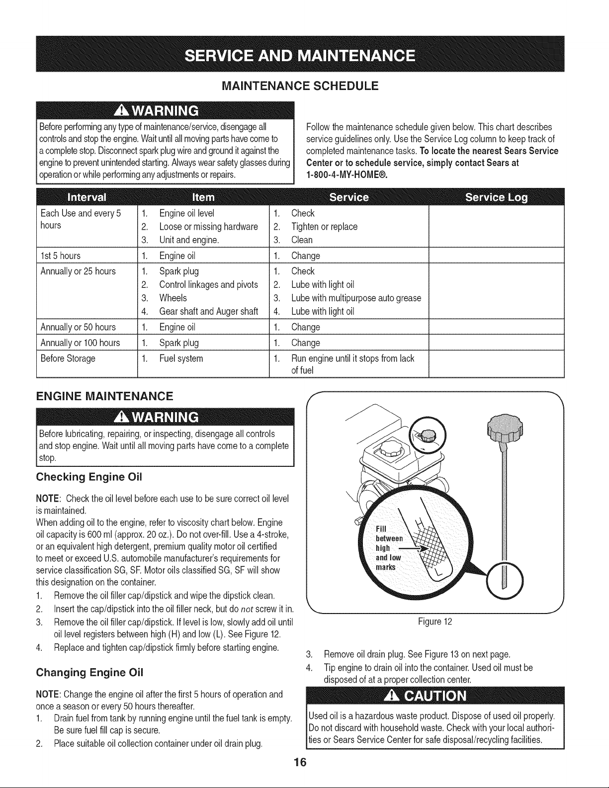
Followthe maintenanceschedulegiven below.Thischart describes
serviceguidelinesonly. Usethe ServiceLogcolumnto keeptrackof
completedmaintenancetasks.To locate the nearest Sears Service
Centeror to scheduleservice,simplycontactSearsat
1-800-4-MY-HOME®.
1. Check
2. Tightenor replace
3. Clean
1. Change
1. Check
2. Lubewith light oil
3. Lubewith multipurposeautogrease
4. Lubewith light oil
1. Change
1. Change
1. Runengineuntilit stopsfromlack
offuel
ENGINE MAINTENANCE
Beforelubricating,repairing,or inspecting,disengageall controls
Iandstop engine.Wait untilall movingpartshavecometo a complete
_stop.
Checking Engine Oil
NOTE: Checktheoil levelbeforeeachuseto besurecorrectoil level
is maintained.
Whenaddingoilto the engine,referto viscositychart below.Engine
oilcapacityis 600ml (approx.20 oz.). Donot over-fill.Usea 4-stroke,
oran equivalenthighdetergent,premiumqualitymotoroil certified
to meet or exceedU.S.automobilemanufacturer'srequirementsfor
serviceclassificationSG, SR MotoroilsclassifiedSG, SFwill show
thisdesignationonthe container.
1. Removethe oil fillercap/dipstickandwipethe dipstickclean.
2. Insertthe cap/dipstickintotheoil filler neck,butdo not screwit in.
3. Removethe oil fillercap/dipstick.Iflevelislow,slowlyadd oiluntil
oil levelregistersbetweenhigh(H) and low (L). See Figure12.
4. Replaceand tighten cap/dipstickfirmlybeforestartingengine.
Changing Engine Oil
NOTE:Changethe engineoilafterthe first 5 hoursof operationand
oncea seasonorevery 50 hoursthereafter.
1. Drainfuelfrom tank by runningengineuntilthe fuel tankisempty.
Besurefuel fill cap is secure.
2. Placesuitableoil collectioncontainerunderoildrainplug.
Figure12
J
3. Removeoil drain plug.SeeFigure13on nextpage.
4. Tip engineto drain oil intothe container.Usedoil mustbe
disposedof at a propercollectioncenter.
Usedoil isa hazardouswasteproduct.Disposeof usedoil properly.
IDo notdiscardwith householdwaste.Checkwithyour localauthori-
lties or SearsServiceCenterfor safe disposal/recyclingfacilities.
16
.
6.
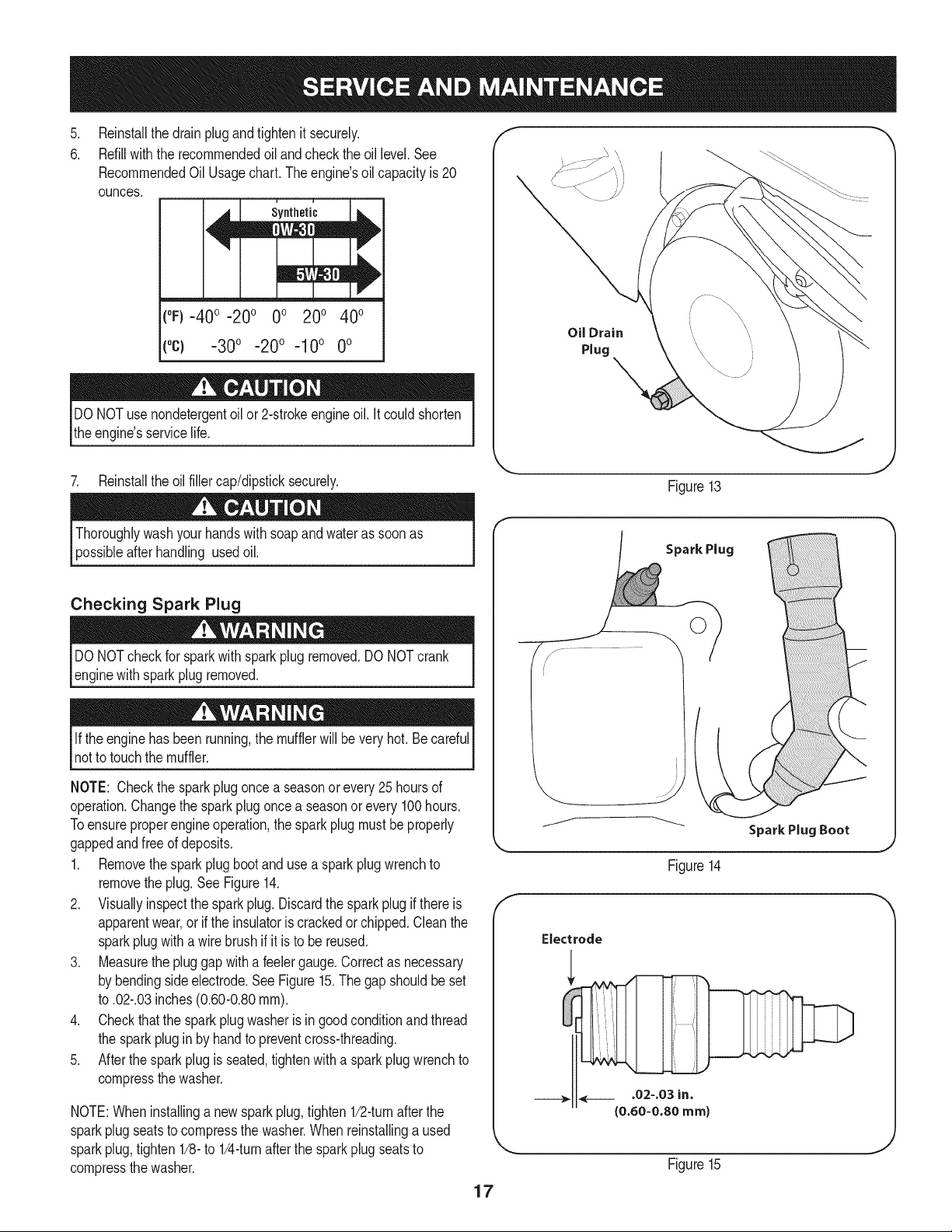
Reinstallthe drain plugandtightenit securely.
Refillwiththe recommendedoil and checkthe oil level.See
RecommendedOil Usagechart.Theengine'soil capacityis 20
ounces.
(%-400 -200 0o 200 400
("c) -300 -200 -10° 0°
DONOTuse nondetergentoil or 2-strokeengineoil. itcould shorten
the engine'sservicelife.
7. Reinstallthe oilfillercap/dipsticksecurely.
Oil Drain
Plug
Figure13
afterhandling usedoil.
Checking Spark Plug
DO NOTcheckfor sparkwithspark plug removed.DO NOTcrank
enginewithsparkplug removed.
Ifthe enginehasbeenrunning,the mufflerwill bevery hot.Becareful
notto touch the muffler.
NOTE: Checkthe sparkplugoncea seasonorevery25hoursof
operation.Changethe sparkplugoncea seasonor every 100hours.
Toensureproperengineoperation,the sparkplugmustbe properly
gappedandfreeof deposits.
1. Removethespark plug bootand use a sparkplugwrenchto
removethe plug.See Figure14.
2. Visuallyinspectthe sparkplug.Discardthe sparkplugif thereis
apparentwear,or if the insulatoris crackedor chipped.Cleanthe
sparkplugwith a wirebrush if it is to be reused.
3. Measurethe pluggapwitha feelergauge.Correctas necessary
by bendingsideelectrode.SeeFigure15.The gap shouldbe set
to .02-.03inches(0.60-0.80ram).
4. Checkthatthe sparkplug washeris ingood conditionand thread
the sparkplug in by handto preventcross-threading.
5. After thespark plug is seated,tightenwitha spark plugwrenchto
compressthe washer.
NOTE:Wheninstallinga newsparkplug,tighten1/2-turnafter the
sparkplugseatsto compressthe washer.Whenreinstallinga used
sparkplug,tighten1/8-to 1/4-turnafter the sparkplugseatsto
compressthe washer.
17
Spark Plug
0
J
Figure14
Electrode
Figure15
become hotandcan inc.
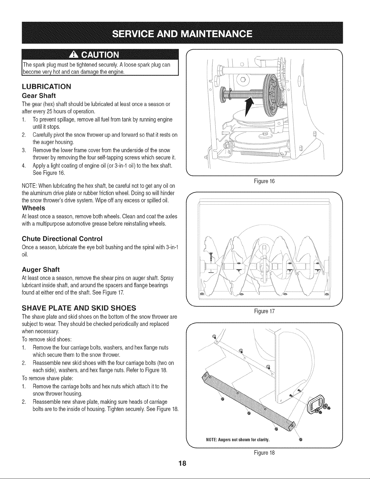
LUBRICATION
Gear Shaft
Thegear(hex)shaft shouldbe lubricatedat leastoncea seasonor
afterevery25 hoursof operation.
1. Topreventspillage,removeall fuel fromtank by runningengine
until it stops.
2. Carefullypivotthe snowthrowerupand forwardso that it restson
theaugerhousing.
3. Removethe lowerframecover fromthe undersideof the snow
throwerby removingthe four self-tappingscrewswhichsecureit.
4. Applya lightcoatingof engineoil (or3-in-1oil) to the hexshaft.
SeeFigure16.
NOTE:Whenlubricatingthe hexshaft, be carefulnotto get any oil on
thealuminumdriveplateor rubberfrictionwheel.Doingsowill hinder
the snowthrower'sdrive system.Wipeoff anyexcessor spilledoil.
Wheels
At least oncea season,removebothwheels.Cleanandcoattheaxles
witha multipurposeautomotivegreasebeforereinstallingwheels.
Chute Directional Control
Oncea season,lubricatethe eye boltbushingand thespiralwith 3-in-1
oil.
Auger Shaft
At least oncea season,removethe shearpinson augershaft.Spray
lubricantinsideshaft,andaroundthe spacersandflangebearings
foundat eitherendof the shaft.SeeFigure17.
f
Figure16
SHAVE PLATE AND SKID SHOES
The shaveplateand skidshoesonthe bottomof the snowthrowerare
subjectto wear.Theyshouldbecheckedperiodicallyandreplaced
whennecessary.
To removeskid shoes:
1. Removethe four carriagebolts,washers,and hex flangenuts
whichsecurethemto the snowthrower.
2. Reassemblenew skidshoeswiththe fourcarriagebolts (two on
eachside),washers,andhex flangenuts.Referto Figure18.
To removeshaveplate:
1. Removethe carriageboltsand hexnutswhichattachit to the
snowthrowerhousing.
2. Reassemblenew shaveplate,makingsureheadsof carriage
boltsare to the insideof housing.Tightensecurely.See Figure18.
Figure17
NOTE:Augers not shown for clarity.
Figure18
/
/
/
/
18
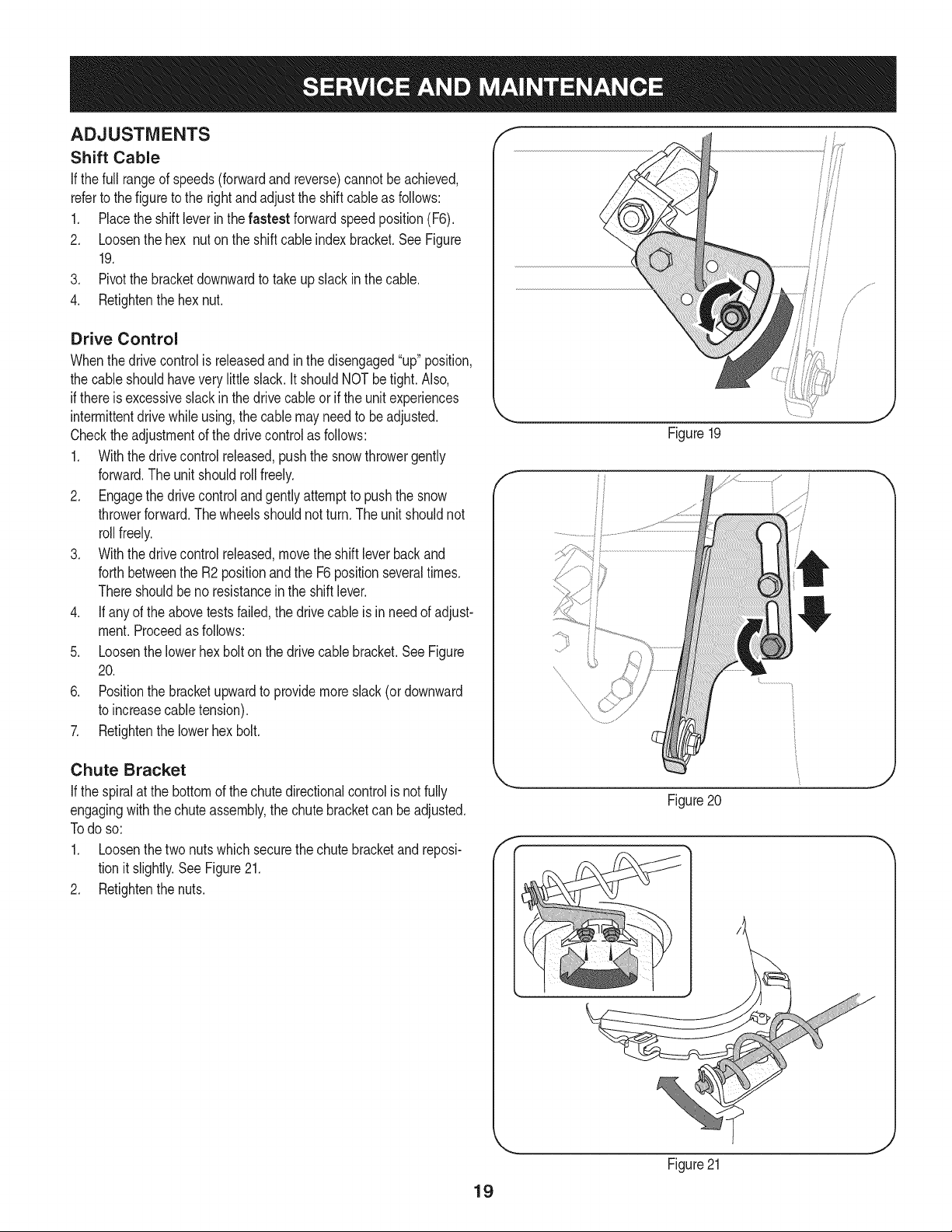
ADJUSTMENTS
Shift Cable
If thefull rangeof speeds(forwardandreverse)cannotbe achieved,
referto the figureto the rightandadjustthe shift cableas follows:
1. Placethe shiftleverin thefastest forwardspeedposition(F6).
2. Loosenthe hex nuton the shiftcable indexbracket.SeeFigure
19.
3. Pivotthe bracketdownwardto take up slack inthe cable.
4. Retightenthehex nut.
Drive Control
Whenthedrivecontrolis releasedandin thedisengaged"up"position,
the cableshouldhaveverylittle slack.It shouldNOTbetight. Also,
if thereis excessiveslackin thedrive cableor if the unitexperiences
intermittentdrivewhileusing,the cable mayneed to beadjusted.
Checktheadjustmentof the drivecontrolas follows:
1. Withthedrivecontrol released,pushthe snowthrowergently
forward.The unitshouldroll freely.
2. Engagethe drivecontrolandgentlyattemptto pushthe snow
throwerforward.Thewheelsshouldnotturn.The unitshouldnot
rollfreely.
3. With thedrivecontrol released,movethe shift leverbackand
forthbetweenthe R2positionand the F6 positionseveraltimes.
Thereshouldbeno resistancein the shiftlever.
4. If anyof the abovetests failed,the drivecable is in needof adjust-
ment.Proceedas follows:
5. Loosenthe lowerhexbolt on the drivecable bracket.SeeFigure
20.
6. Positionthe bracketupwardto providemoreslack(or downward
to increasecabletension).
7. Retightenthe lowerhex bolt.
Chute Bracket
If the spiralat the bottomof the chutedirectionalcontrol is notfully
engagingwiththe chuteassembly,the chutebracketcan beadjusted.
Todo so:
1. Loosenthe twonutswhichsecurethechutebracketandreposi-
tion it slightly.See Figure21.
2. Retightenthe nuts.
Figure19
f
Figure20
f
19
Figure21
Auger Control f "_
Referto the Assemblysectionfor instructionsonadjustingtheauger
controlcable.
Skid Shoes
Referto the Assemblysectionfor instructionsonadjustingthe skid
shoes.
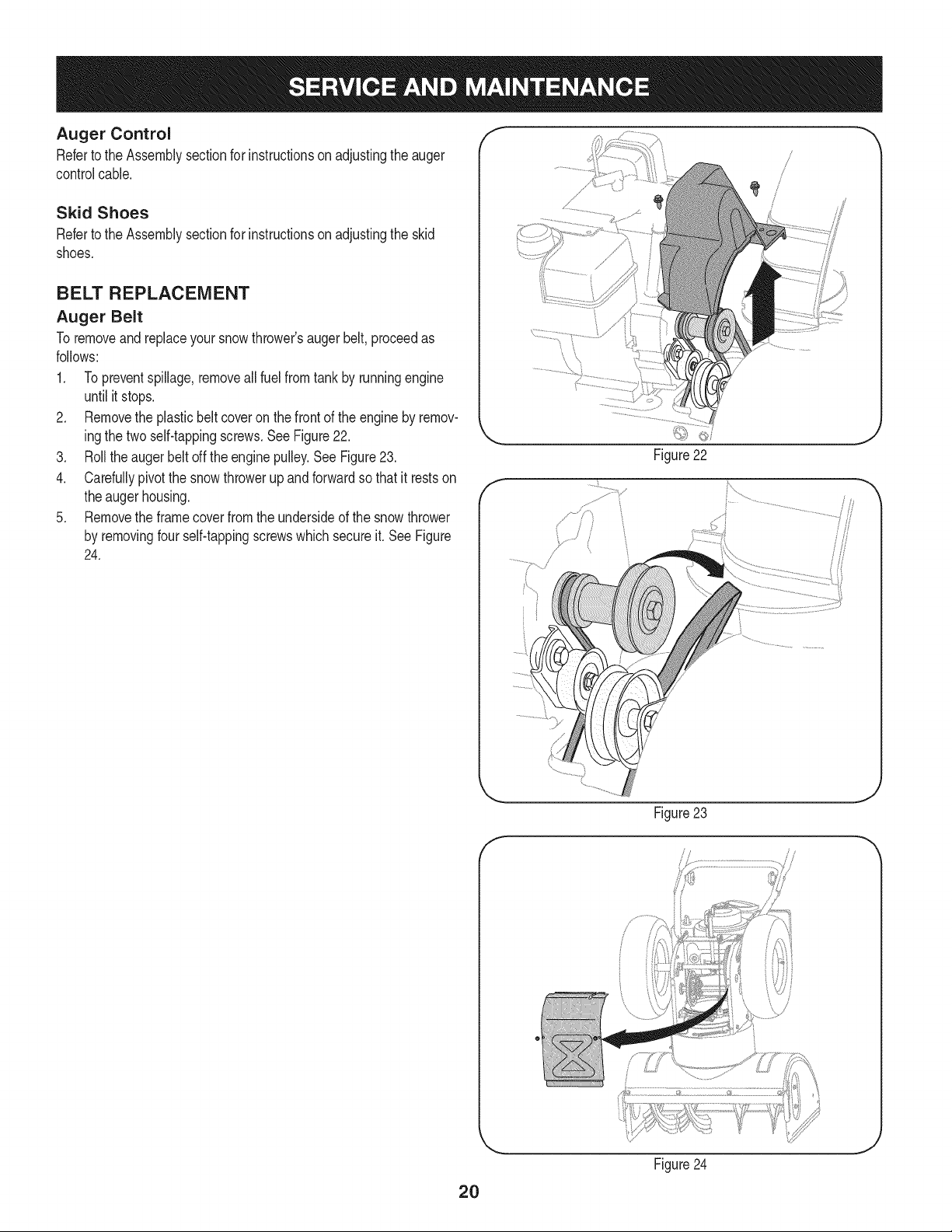
BELT REPLACEMENT
Auger Belt
To removeand replaceyoursnow thrower'sauger belt, proceedas
follows:
1. Topreventspillage,removeall fuel fromtank by runningengine
until itstops.
2. Removethe plasticbelt coveronthe front of the engineby remov-
ingthe twoself-tappingscrews.SeeFigure22.
3. Rollthe augerbeltoff theenginepulley.See Figure23.
4. Carefullypivotthe snowthrowerupand forwardso that itrestson
theaugerhousing.
5. Removethe framecoverfromthe undersideof the snowthrower
by removingfourself-tappingscrewswhichsecureit. See Figure
24.
f
Figure22
J
f
Figure 23
//
2O
Figure24
J
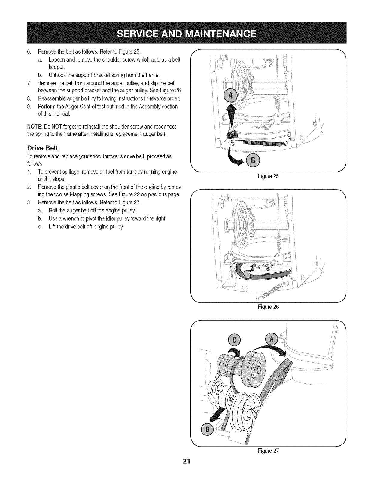
6. Removethebeltasfollows.RefertoFigure25.
a. Loosenandremovetheshoulderscrewwhichactsasabelt
keeper.
b. Unhookthesupportbracketspringfromtheframe.
7. Removethebeltfromaroundtheaugerpulley,andslipthebelt
betweenthesupportbracketandtheaugerpulley.SeeFigure26.
8. Reassembleaugerbeltbyfollowinginstructionsinreverseorder.
9. PerformtheAugerControltestoutlinedintheAssemblysection
ofthismanual.
NOTE:DoNOTforgettoreinstalltheshoulderscrewandreconnect
thespringtotheframeafterinstallingareplacementaugerbelt.
Drive Belt
Toremoveand replaceyoursnowthrower'sdrivebelt,proceedas
follows:
1. Topreventspillage,removeall fuel fromtankby runningengine
untilit stops.
2. Removetheplasticbelt coveronthe front of the engineby remov-
ingthe twoself-tappingscrews.See Figure22 on previouspage.
3. Removethebelt as follows.Referto Figure27.
a. Rollthe augerbeltoff theenginepulley.
b. Use a wrenchto pivotthe idlerpulleytowardthe right.
c. Lift the drivebelt off enginepulley.
/" }
Figure25
Figure26
21
Figure27
4, Carefullypivotthesnowthrowerupandforwardsothatitrestson
theaugerhousing.
5. Removetheframecoverfromtheundersideofthesnowthrower
byremovingfourself-tappingscrewswhichsecureit.Referto
Figure24,
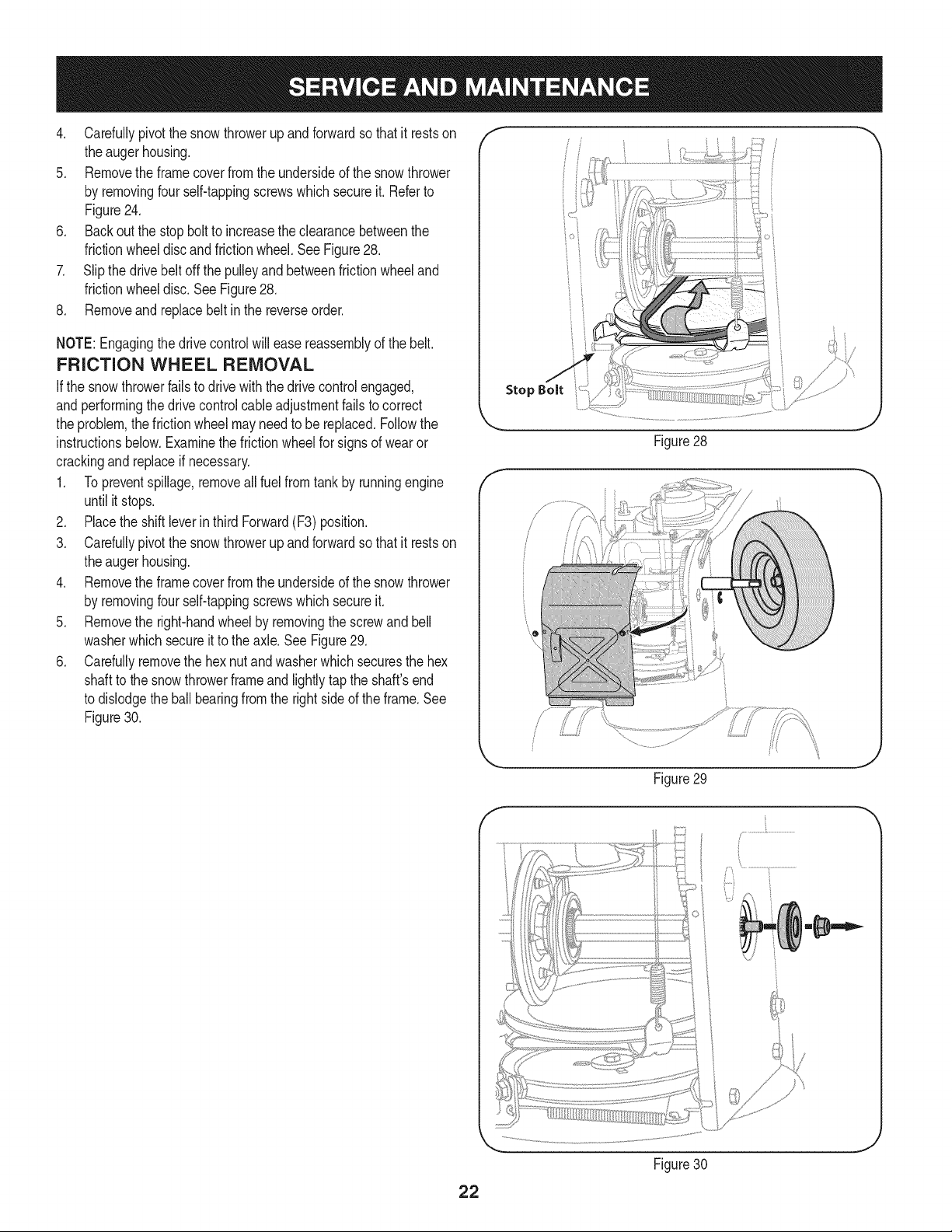
6. Backoutthestopbolttoincreasetheclearancebetweenthe
frictionwheeldiscandfrictionwheel,SeeFigure28,
7. Slipthedrivebeltoffthepulleyandbetweenfrictionwheeland
frictionwheeldisc,SeeFigure28,
8, Removeandreplacebeltinthereverseorder,
NOTE:Engagingthedrivecontrolwilleasereassemblyofthebelt.
FRICTION WHEEL REMOVAL
Ifthe snowthrowerfailsto drive with thedrivecontrol engaged,
andperformingthe drivecontrolcableadjustmentfails to correct
the problem,the frictionwheelmayneedto be replaced.Followthe
instructionsbelow.Examinethe frictionwheelfor signsof wearor
crackingandreplaceif necessary.
1. Topreventspillage,removeall fuel fromtank by runningengine
until it stops.
2. Placethe shiftleverin third Forward(F3) position.
3. Carefullypivotthe snowthrowerupand forwardso that it restson
theaugerhousing.
4. Removethe framecoverfromthe undersideof the snowthrower
by removingfourself-tappingscrewswhichsecureit.
5. Removethe right-handwheelby removingthe screwandbell
washerwhichsecureit to theaxle.See Figure29.
6. Carefullyremovethe hexnut and washerwhichsecuresthe hex
shaftto the snowthrowerframeand lightlytap the shaft'send
to dislodgethe ball bearingfrom the rightsideof theframe.See
Figure30.
Stop Bolt
Figure28
/ ii
J
Figure29
Figure30
J
22
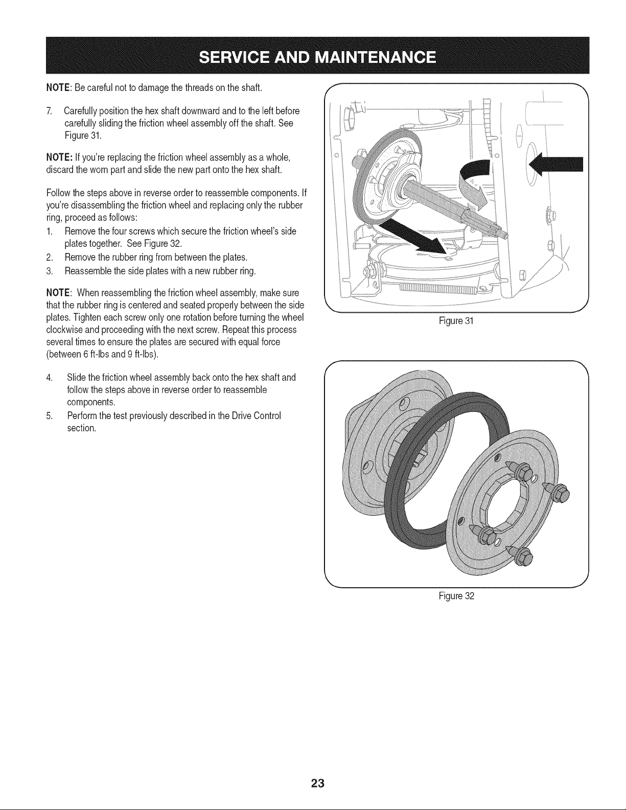
NOTE:Becarefulnot to damagethe threadson the shaft,
7. Carefullypositionthe hexshaftdownwardandto the left before
carefullyslidingthe frictionwheelassemblyoff the shaft.See
Figure31.
NOTE: If you'rereplacingthe frictionwheelassemblyas a whole,
discardthe wornpartand slidethe newpart ontothe hexshaft.
Followthe stepsabovein reverseorder to reassemblecomponents.If
you'redisassemblingthe frictionwheeland replacingonly the rubber
ring,proceedas follows:
1. Removethefour screwswhichsecurethe frictionwheel'sside
platestogether. SeeFigure32.
2. Removethe rubberringfrom betweenthe plates.
3. Reassemblethe side plateswith a newrubberring.
NOTE: Whenreassemblingthe frictionwheelassembly,makesure
thatthe rubberringis centeredand seatedproperlybetweenthe side
plates.Tighteneachscrewonlyone rotationbeforeturningthe wheel
clockwiseandproceedingwiththe next screw.Repeatthisprocess
severaltimes toensurethe platesaresecuredwith equalforce
(between6 ft-lbsand 9 ft-lbs).
4. Slide the frictionwheelassemblybackonto the hexshaftand
followthestepsabovein reverseorderto reassemble
components.
5. Performthe testpreviouslydescribedin the DriveControl
section.
Figure31
... j
Figure32
23
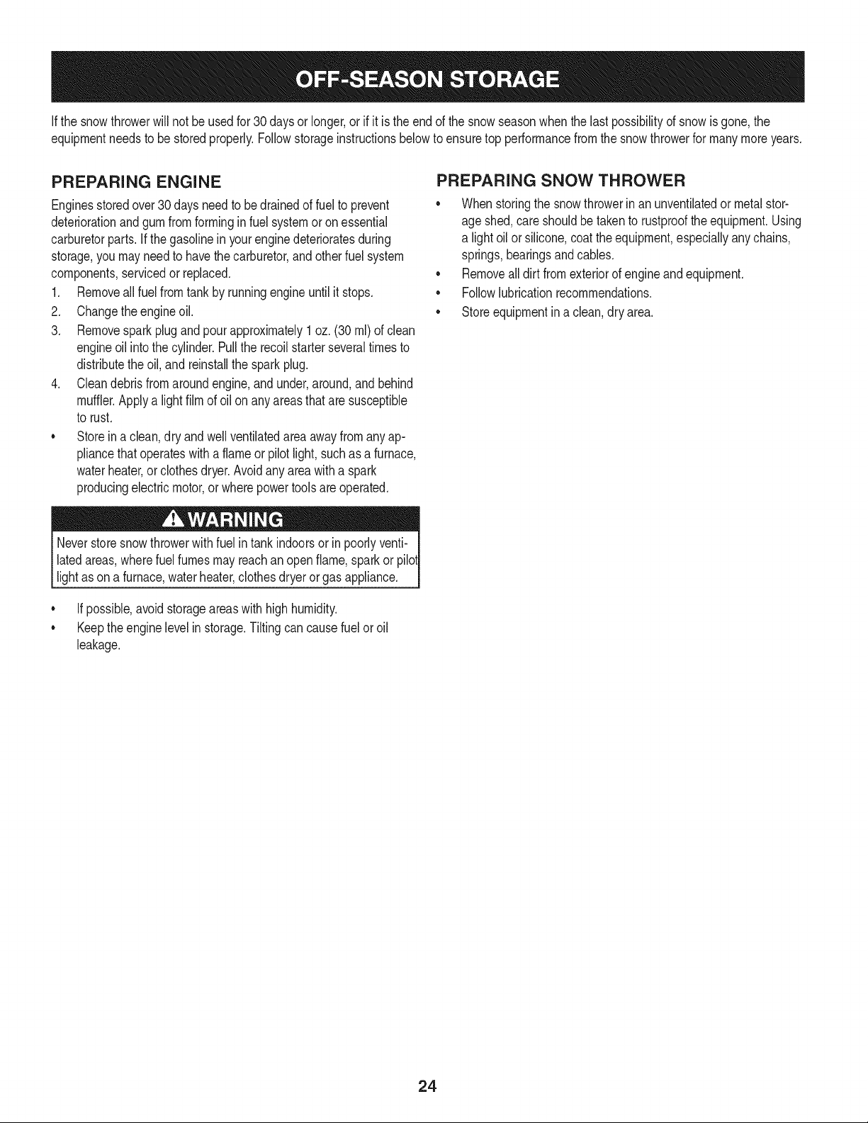
Ifthe snowthrowerwillnot be usedfor30 daysor longer,or if it is the endof the snowseasonwhenthe lastpossibilityof snowis gone,the
equipmentneedsto be storedproperly.Followstorageinstructionsbelowto ensuretop performancefromthe snowthrowerfor manymoreyears.
PREPARING ENGINE
Enginesstoredover30days need to bedrainedof fuel to prevent
deteriorationand gumfrom formingin fuel systemor onessential
carburetorparts.If thegasolineinyourenginedeterioratesduring
storage,youmayneedto havethe carburetor,and otherfuel system
components,servicedor replaced.
1. Removeall fuel fromtank by runningengineuntil it stops.
2. Changethe engineoil.
3. Removesparkplug and pour approximately1 oz. (30 rnl) of clean
engineoil intothe cylinder.Pullthe recoilstarterseveraltimesto
distributetheoil, and reinstallthe sparkplug.
4. Cleandebrisfrom aroundengine,and under,around,andbehind
muffler.Applya lightfilmof oil on anyareasthat are susceptible
to rust.
• Storein a clean,dry and wellventilatedareaawayfromanyap-
pliancethatoperateswith a flame or pilotlight, such as a furnace,
waterheater,or clothesdryer.Avoidany areawitha spark
producingelectricmotor,or wherepowertools are operated.
Neverstoresnowthrowerwithfuel in tank indoorsor in poorlyventi-
latedareas,wherefuel fumesmayreachan openflame,sparkor pilol
lightas on a furnace,waterheater,clothesdryer or gas appliance.
• If possible,avoidstorageareaswithhighhumidity.
• Keepthe enginelevelin storage.Tiltingcan causefuel oroil
leakage.
PREPARING SNOW THROWER
Whenstoringthe snowthrowerin anunventilatedormetal stor-
age shed,careshouldbetaken to rustprooftheequipment.Using
a light oil or silicone,coat theequipment,especiallyanychains,
springs,bearingsandcables.
• Removealldirt fromexteriorof engineandequipment.
• Followlubricationrecommendations.
• Storeequipmentin a clean,dry area.
24
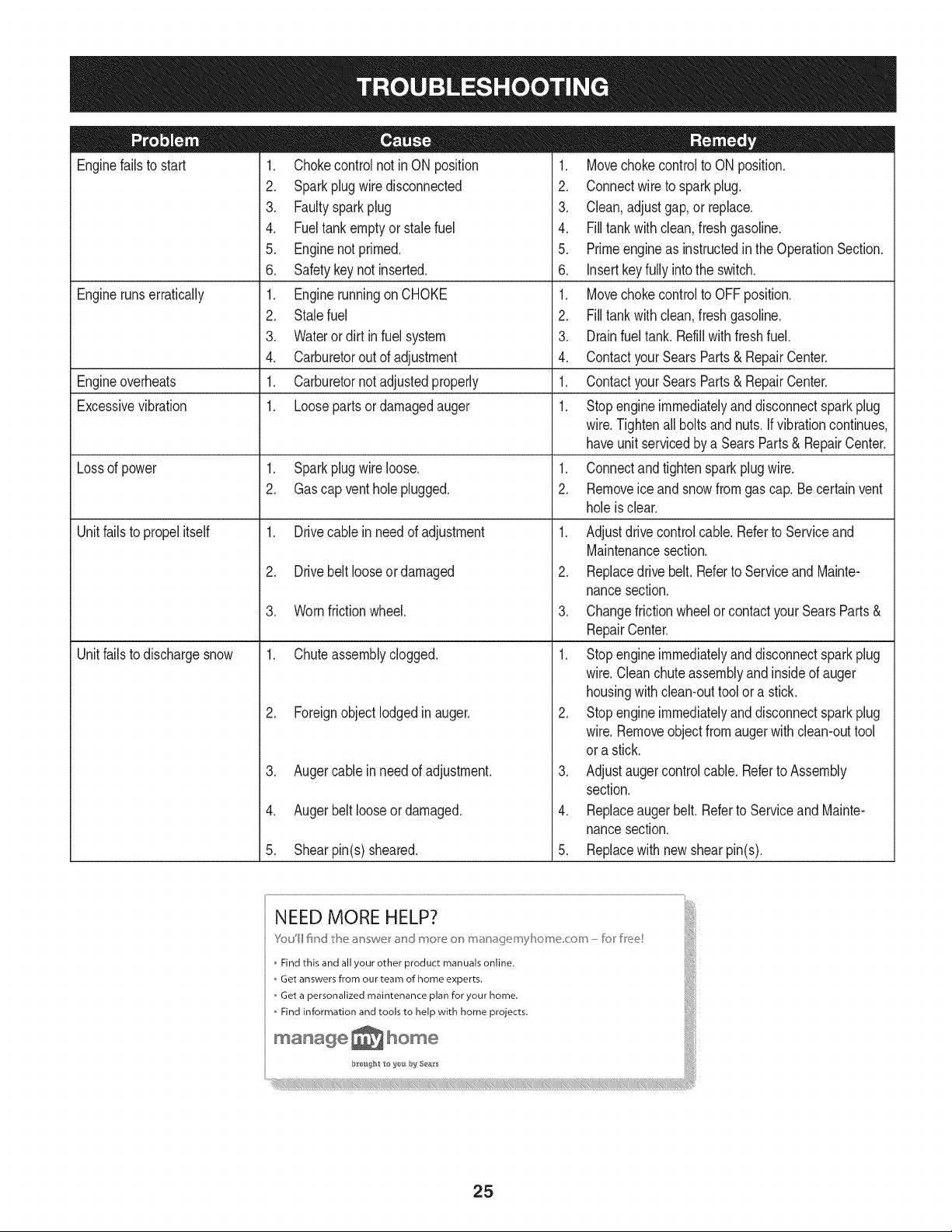
Enginefailsto start
Enginerunserratically
Engineoverheats
Excessivevibration
Lossof power
Unitfailsto propel itself
Unitfailsto dischargesnow
1. Chokecontrolnot inON position
2. Sparkplugwire disconnected
3. Faultysparkplug
4. Fueltank emptyor stale fuel
5. Enginenotprimed.
6. Safetykeynot inserted.
1. Enginerunningon CHOKE
2. Stalefuel
3. Wateror dirt in fuel system
4. Carburetorout of adjustment
1. Carburetornot adjustedproperly
1. Loosepartsor damagedauger
1. Sparkplugwire loose.
2. Gascap ventholeplugged.
1. Drivecable inneedof adjustment
2. Drivebelt looseordamaged
3. Wornfrictionwheel.
1. Chuteassemblyclogged.
2. Foreignobject lodgedin auger.
3. Augercablein needof adjustment.
4. Augerbelt looseordamaged.
5. Shearpin(s) sheared.
1. Movechokecontrolto ONposition.
2. Connectwireto sparkplug.
3. Clean,adjustgap,or replace.
4. Filltank with clean, freshgasoline.
5. Primeengineas instructedin the OperationSection.
6. Insertkeyfully intothe switch.
1. Movechokecontrolto OFFposition.
2. Filltank with clean, freshgasoline.
3. Drainfueltank. Refillwithfreshfuel.
4. ContactyourSearsParts& RepairCenter.
1. ContactyourSearsParts& RepairCenter.
1. Stopengineimmediatelyand disconnectsparkplug
wire.Tightenall boltsand nuts.Ifvibrationcontinues,
haveunitservicedbya SearsParts& RepairCenter.
1. Connectand tightenspark plugwire.
2. Removeice andsnowfromgascap.Becertainvent
holeis clear.
1. Adjustdrivecontrolcable. Referto Serviceand
Maintenancesection.
2. Replacedrive belt.Referto ServiceandMainte-
nancesection.
3. Changefrictionwheelor contactyour SearsParts&
RepairCenter.
1. Stopengineimmediatelyand disconnectsparkplug
wire.Cleanchuteassemblyandinsideof auger
housingwithclean-outtool ora stick.
2. Stopengineimmediatelyand disconnectsparkplug
wire.Removeobjectfromaugerwith clean-outtool
ora stick.
3. Adjustaugercontrolcable. Referto Assembly
section.
4. Replaceauger belt. Referto ServiceandMainte-
nancesection.
5. Replacewith new shearpin(s).
25
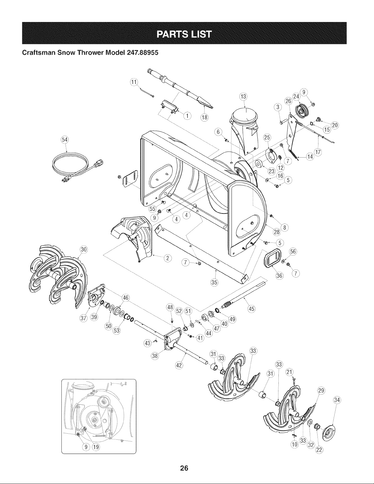
Craftsman Snow Thrower IViodel 247.88955
35)
/ !
/
26
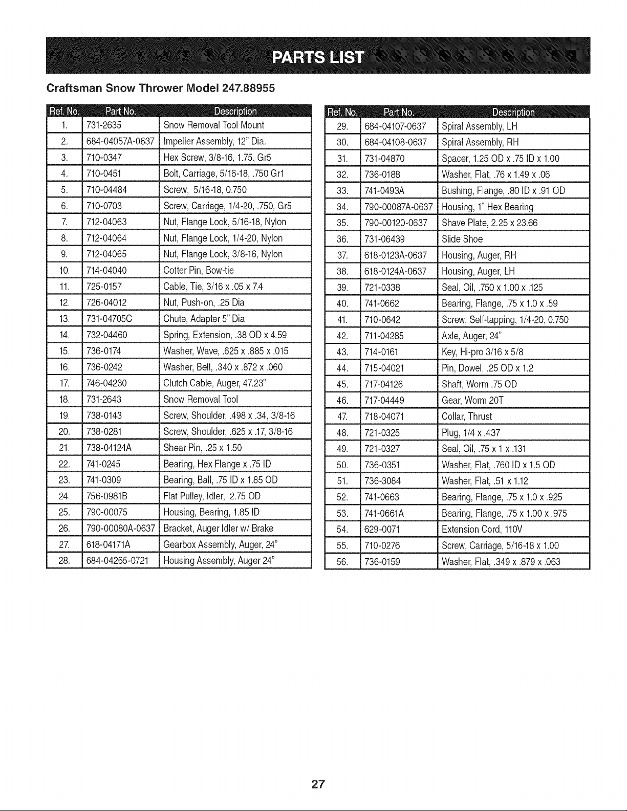
Craftsman Snow Thrower IViodel 247.88955
D = 0 0
731-2635 SnowRemovalToolMount
2. 684-04057A-0637 ImpellerAssembly,12"Dia.
3. 710-0347 HexScrew,3/8-16,1.75,Gr5
4. 710-0451 Bolt,Carriage,5/16-18,.750Grl
5. 710-04484 Screw, 5/16-18,0.750
6. 710-0703 Screw,Carriage,1/4-20,.750,Gr5
7. 712-04063 Nut,FlangeLock,5/16-18,Nylon
8. 712-04064 Nut,FlangeLock,1/4-20,Nylon
9. 712-04065 Nut,FlangeLock,3/8-16,Nylon
10. 714-04040 Cotter Pin,Bow-tie
11. 725-0157 Cable,Tie,3/16 x .05 x 7.4
12. 726-04012 Nut,Push-on,.25 Dia
13. 731-04705C Chute,Adapter5" Dia
14. 732-04460 Spring,Extension,.38 ODx 4.59
15. 736-0174 Washer,Wave,.625x .885x .015
16. 736-0242 Washer,Bell,.340x .872x .060
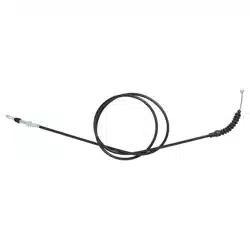
17. 746-04230 ClutchCable,Auger,47.23"
18. 731-2643 Snow RemovalTool
19. 738-0143 Screw,Shoulder,.498x .34,3/8-16
20. 738-0281 Screw,Shoulder,.625x .17,3/8-16
21. 738-04124A Shear Pin,.25 x 1.50
22. 741-0245 Bearing,Hex Flangex .75ID
23. 741-0309 Bearing,Ball,.75ID x 1.85OD
24. 756-0981B FlatPulley,Idler, 2.75OD
25. 790-00075 Housing,Bearing,1.85ID
26. 790-00080A-0637 Bracket,AugerIdlerw/Brake
27. 618-04171A GearboxAssembly,Auger,24"
28. 684-04265-0721 HousingAssembly,Auger24"
D = O 0
684-04107-0637 SpiralAssembly,LH
30. 684-04108-0637 SpiralAssembly,RH
31. 731-04870 Spacer,1.25OD x .75 ID x 1.00
32. 736-0188 Washer,Flat, .76x 1.49x .06
33. 741-0493A Bushing,Flange,.80 ID x .91OD
34. 790-00087A-0637 Housing,1"Hex Bearing
35. 790-00120-0637 ShavePlate,2.25 x 23.66
36. 731-06439 SlideShoe
37. 618-0123A-0637 Housing,Auger,RH
38. 618-0124A-0637 Housing,Auger,LH
39. 721-0338 Seal,Oil, .750x 1.00x .125
40. 741-0662 Bearing,Flange,.75x 1.0x .59
41. 710-0642 Screw,Self-tapping,1/4-20,0.750
42. 711-04285 Axle,Auger,24"
43. 714-0161 Key,Hi-pro3/16x 5/8
44. 715-04021 Pin, Dowel,.25OD x 1.2
45. 717-04126 Shaft,Worm.75OD
46. 717-04449 Gear,Worm20T
47. 718-04071 Collar,Thrust
48. 721-0325 Plug,1/4 x .437
49. 721-0327 Seal,Oil, .75x 1x .131
50. 736-0351 Washer,Flat, .760IDx 1.50D
51. 736-3084 Washer,Flat, .51x 1.12
52. 741-0663 Bearing,Flange,.75x 1.0x .925
53. 741-0661A Bearing,Flange,.75x 1.00x .975
54. 629-0071 ExtensionCord, 110V
55. 710-0276 Screw,Carriage,5/16-18x 1.00
56. 736-0159 Washer,Fiat, .349x .879x .063
27
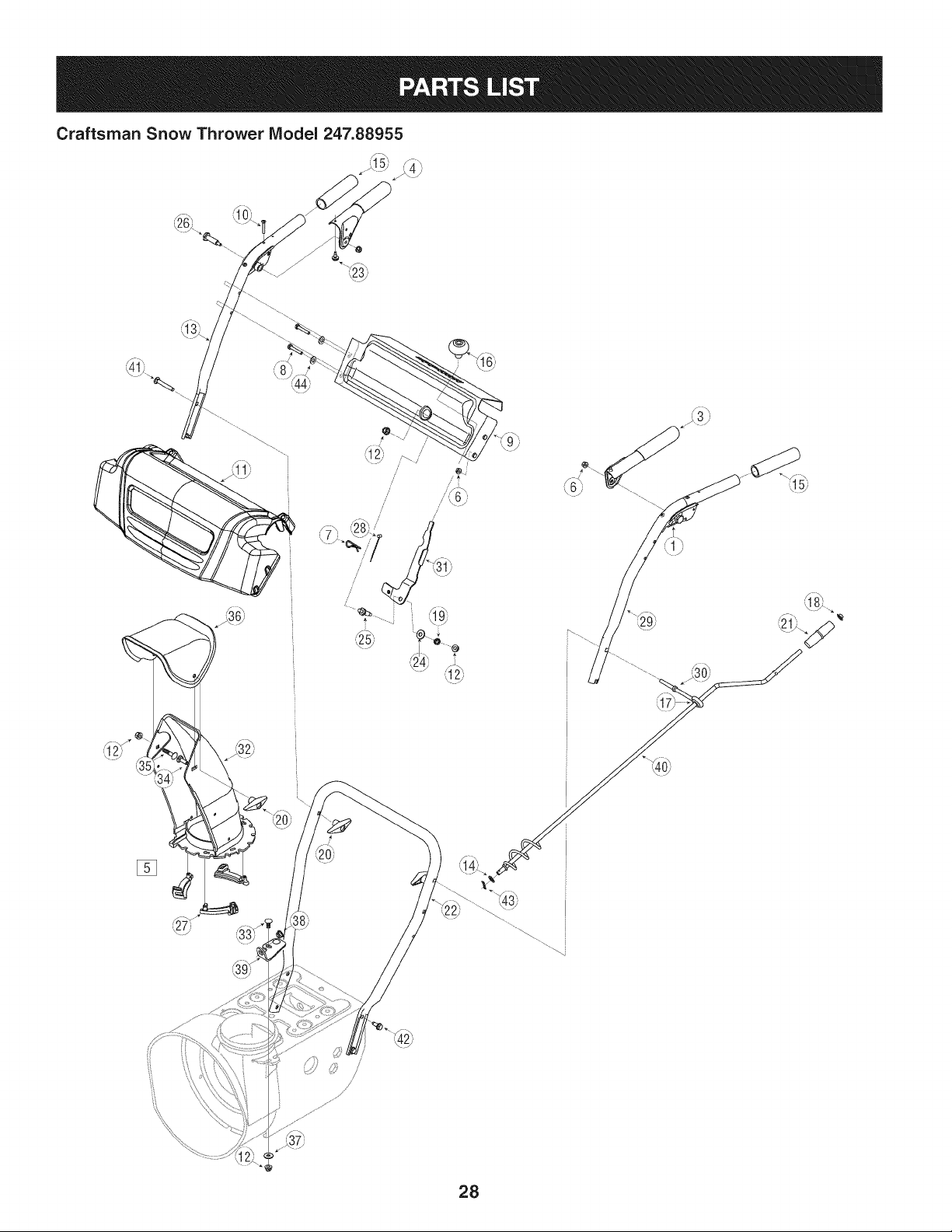
Craftsman Snow Thrower Model 247.88955
/-\
[]
28
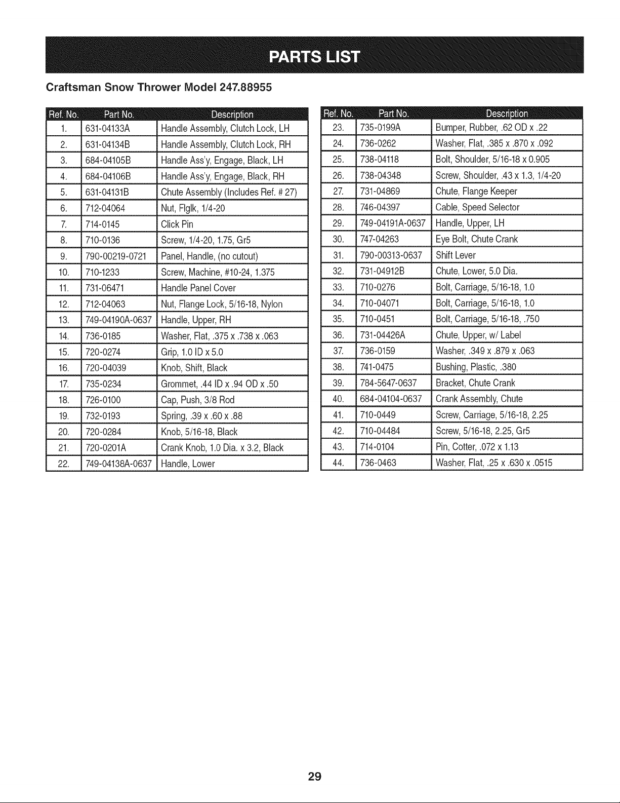
Craftsman Snow Thrower IViodel 247.88955
D = _
631-04133A HandleAssembly,ClutchLock, LH
2. 631-04134B HandleAssembly,ClutchLock, RH
3. 684-04105B HandleAss'y,Engage,Black,LH
4. 684-04106B HandleAss'y,Engage,Black,RH
5. _631-04131B . ChuteAssembly(IncludesRef.# 27)
6. 712-04064 Nut, Flglk,1/4-20
7. 714-0145 ClickPin
8. 710-0136 Screw,1/4-20,1.75,Gr5
9. 790-00219-0721 Panel,Handle,(nocutout)
10. 710-1233 Screw,Machine,#10-24,1.375
11. 731-06471 HandlePanelCover
12. 712-04063 Nut, FlangeLock,5/16-18,Nylon
13. 749-04190A-0637 Handle,Upper,RH
14. 736-0185 Washer,Fiat,.375x .738x .063
15. 720-0274 Grip,1.0IDx 5.0
16. 720-04039 Knob,Shift,Black
17. 735-0234 Grommet,.44 IDx .94 OD x .50
18. 726-0100 Cap,Push,3/8 Rod
19. 732-0193 Spring,.39x .60x .88
20. 720-0284 Knob,5/16-18,Black
21. 720-0201A CrankKnob,1.0Dia. x 3.2, Black
22. 749-04138A-0637 Handle,Lower
735-0199A Bumper,Rubber,.62 ODx .22
24. ,736-0262 LWasher,Flat, .385x .870x .092
25. 738-04118 Bolt,Shoulder,5/16-18x 0.905
26. 738-04348 Screw,Shoulder,.43x 1.3,1/4-20
27. 731-04869 Chute,FlangeKeeper
28. 746-04397 Cable,SpeedSelector
29. 749-04191A-0637 Handle,Upper,LH
30. 747-04263 EyeBolt,ChuteCrank
31. 790-00313-0637 ShiftLever
32. 731-04912B Chute,Lower,5.0 Dia.
33. 710-0276
34. 710-04071
35. 710-0451
36. 731-04426A
3_ 736-0159
38. 741-0475
39. 784-5647-0637
40. 684-04104-0637
Bolt,Carriage,5/16-18,1.0
Bolt,Carriage,5/16-18,1.0
Bolt,Carriage,5/16-18,.750
Chute,Upper,w/Label
Washer,.349x .879x .063
Bushing,Plastic,.380
Bracket,ChuteCrank
CrankAssembly,Chute
41. 710-0449 Screw,Carriage,5/16-18,2.25
42. 710-04484 Screw,5/16-18,2.25,Gr5
43. 714-0104 Pin,Cotter,.072x 1.13
44. 736-0463 Washer,Flat, .25x .630x .0515
29
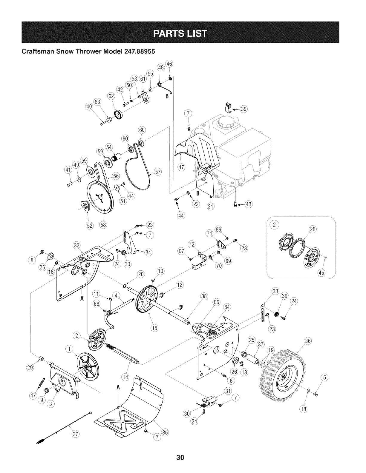
Craftsman Snow Thrower IViodel 247.88955
,_8h, ,%h
//
/
/
30
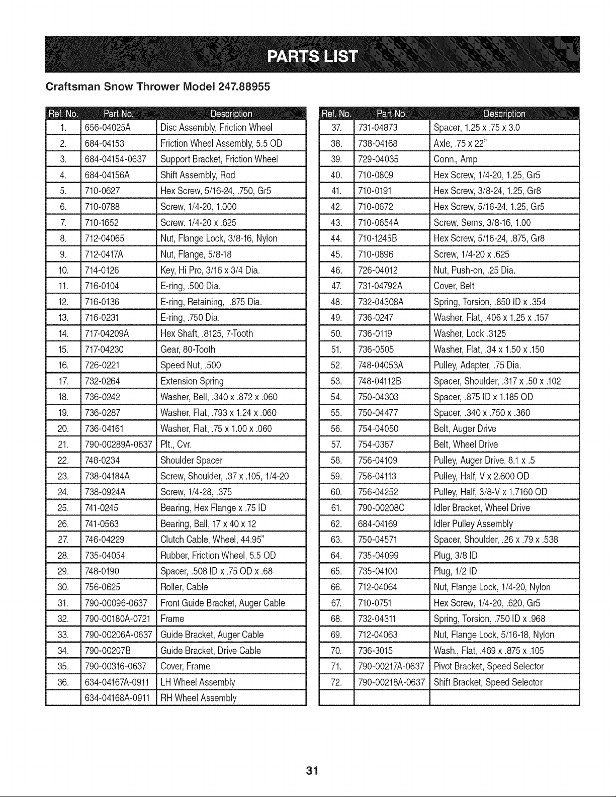
Craftsman Snow Thrower IViodel 247.88955
I = 0 0
656-04025A DiscAssembly,FrictionWheel
2. 684-04153 FrictionWheelAssembly,5.50D
3. 684-04154-0637 SupportBracket,FrictionWheel
4. 684-04156A ShiftAssembly,Rod
5. J 710-0627 J HexScrew,5/16-24,.750,Gr5
6. 710-0788 Screw,1/4-20,1.000
7. 710-1652 Screw,1/4-20x .625
8. 712-04065 Nut,FlangeLock,3/8-16,Nylon
9. 712-0417A Nut,Flange,5/8-18
10. 714-0126 Key,Hi Pro,3/16x 3/4 Dia.
11. 716-0104 E-ring,.500 Dia.
12. 716-0136 E-ring,Retaining, .875Dia.
13. 716-0231 E-ring,.750Dia.
14. 717-04209A HexShaft,.8125,7-Tooth
15. 717-04230 Gear,80-Tooth
16. .726-0221 Speed Nut,.500
17. 732-0264 ExtensionSpring
18. 736-0242 Washer,Bell,.340x .872x .060
19. 736-0287 Washer,Flat,.793x 1.24x .060
20. 736-04161 Washer,Flat,.75x 1.00x .060
21. 790-00289A-0637 Pit.,Cvr.
22. 748-0234 ShoulderSpacer
23. 738-04184A Screw,Shoulder,.37x .105,1/4-20
24. 738-0924A Screw,1/4-28,.375
25. 741-0245 Bearing,Hex Flangex .75 ID
26. 741-0563 Bearing,Ball,17x 40 x 12
27. 746-04229 ClutchCable,Wheel,44.95"
28. 735-04054 Rubber,FrictionWheel,5.50D
29. 748-0190 Spacer,.508IDx .75ODx .68
30. 756-0625 Roller,Cable
31. 790-00096-0637 FrontGuide Bracket,Auger Cable
32. 790-00180A-0721 Frame
33. 790-00206A-0637 GuideBracket,AugerCable
34. 790-00207B Guide Bracket,Drive Cable
35. 790-00316-0637 Cover,Frame
36. 634-04167A-0911 LHWheelAssembly
634-04168A-0911 RHWheelAssembly
D = O e
731-04873 Spacer,1.25x .75x 3.0
38. 738-04168 Axle,.75x 22"
39. 729-04035 Conn.,Amp
40. 710-0809 HexScrew,1/4-20,1.25,Gr5
41. 710-0191 HexScrew,3/8-24, 1.25,Gr8
42. 710-0672 HexScrew,5/16-24,1.25,Gr5
43. 710-0654A Screw,Seres,3/8-16,1.00
44. 710-1245B HexScrew,5/16-24,.875,Gr8
45. 710-0896 Screw,1/4-20x .625
46. 726-04012 Nut, Push-on,.25 Dia.
47. 731-04792A Cover,Belt
48. 732-04308A Spring,Torsion,.850 IDx .354
49. 736-0247 Washer,Flat, .406x 1.25x .157
50. 736-0119 Washer,Lock.3125
51. 736-0505 Washer,Flat, .34x 1.50x .150
52. 748-04053A Pulley,Adapter,.75 Dia.
53. 748-04112B Spacer,Shoulder,.317x .50 x .102
54. 750-04303 Spacer,.875IDx 1.185OD
55. 750-04477 Spacer,.340x .750x .360
56. 754-04050 Belt,AugerDrive
57. 754-0367 Belt,WheelDrive
58. 756-04109 Pulley,AugerDrive,8.1x .5
59. 756-04113 Pulley,Half,V x 2.600OD
60. 756-04252 Pulley,Half,3/8-V x 1.7160OD
61. 790-00208C IdlerBracket,Wheel Drive
62. 684-04169 IdlerPulleyAssembly
63. 750-04571 Spacer,Shoulder,.26 x .79x .538
64. 735-04099 Plug,3/8 ID
65. 735-04100 Plug,1/2 ID
66. 712-04064 Nut,FlangeLock,1/4-20,Nylon
67. 710-0751 HexScrew,1/4-20,.620,Gr5
68. 732-04311 Spring,Torsion,.750ID x .968
69. 712-04063 Nut,FlangeLock,5/16-18,Nylon
70. 736-3015 Wash.,Flat, .469x .875x .105
71. 790-00217A-0637 PivotBracket,SpeedSelector
72. 790-00218A-0637 ShiftBracket,SpeedSelector
31
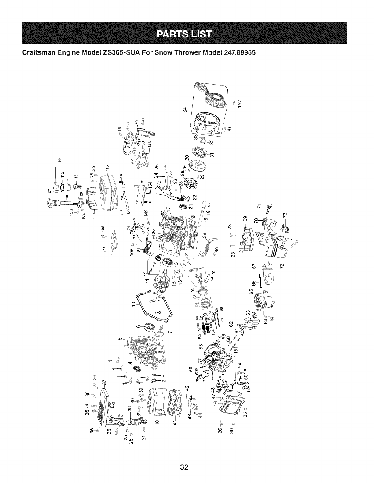
Craftsman Engine Model ZS365-SUA For Snow Thrower Model 247.88955
7
o3
32
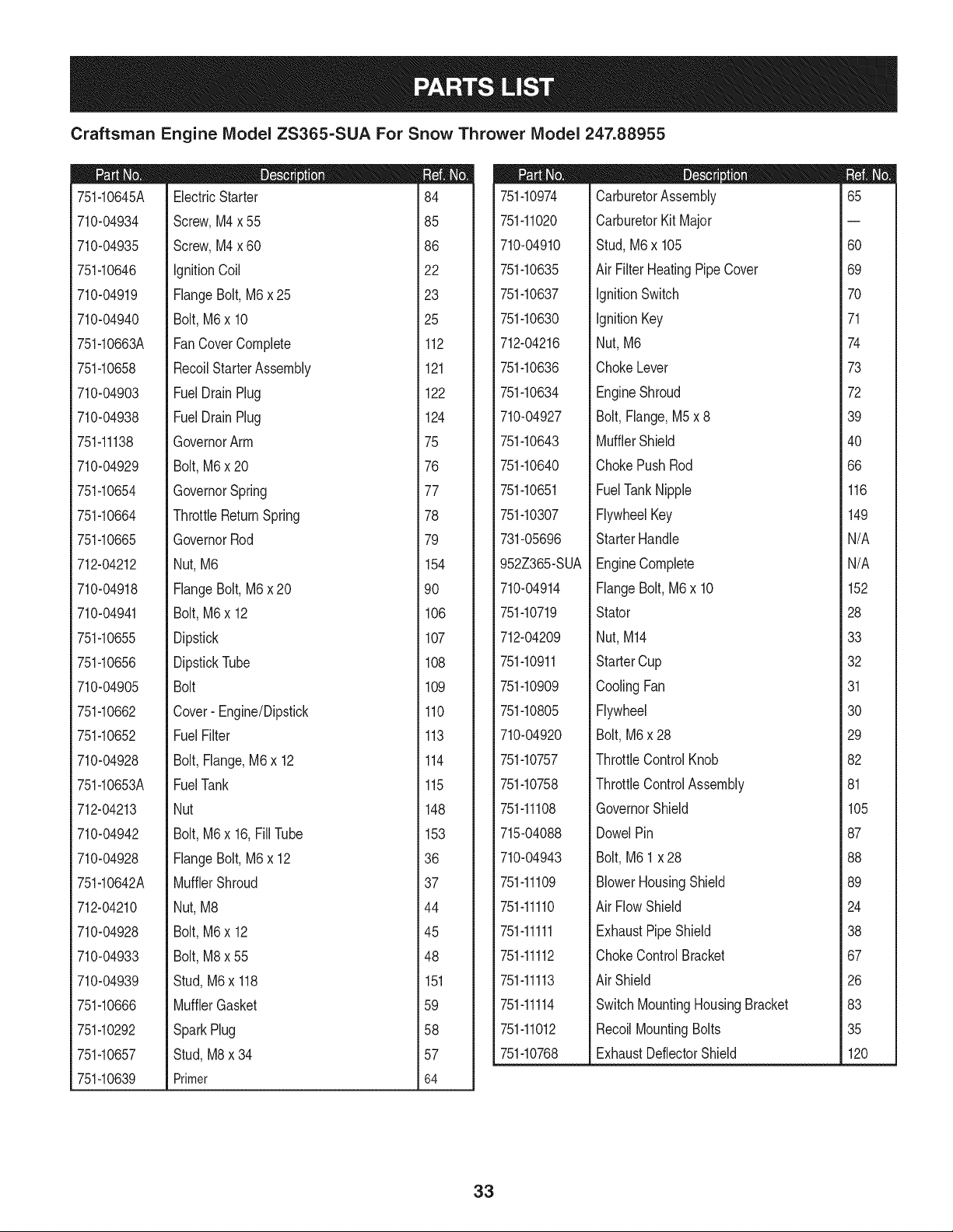
Craftsman Engine IViodel ZS365=SUA For Snow Thrower IViodel 247.88955
751-10645A
710-04934
710-04935
751-10646
710-04919
710-04940
751-10663A
751-10658
710-04903
710-04938
751-11138
710-04929
751-10654
751-10664
751-10665
712-04212
710-04918
710-04941
751-10655
751-10656
710-04905
751-10662
751-10652
710-04928
751-10653A
712-04213
710-04942
710-04928
751-10642A
712-04210
710-04928
710-04933
710-04939
751-10666
751-10292
751-10657
751-10639
D = O
ElectricStarter
Screw,M4 x 55
Screw,M4 x 60
IgnitionCoil
FlangeBolt,M6x 25
Bolt,M6 x 10
FanCoverComplete
RecoilStarterAssembly
FuelDrainPlug
FuelDrainPlug
GovernorArm
Bolt,M6 x 20
GovernorSpring
ThrottleReturnSpring
GovernorRod
Nut, M6
FlangeBolt,M6x 20
Bolt,M6 x 12
Dipstick
DipstickTube
Bolt
Cover- Engine/Dipstick
FuelFilter
Bolt,Flange,M6x 12
FuelTank
Nut
Bolt,M6 x 16,FillTube
FlangeBolt,M6x 12
MufflerShroud
Nut, M8
Bolt,M6 x 12
Bolt,M8 x 55
Stud,M6x 118
MufflerGasket
SparkPlug
Stud,M8x 34
Primer
m
i
184
i
i
i
185
i
i
186
i
i
i
i22
!
i
i
123
i
i
125
i
i
i
i112
!
i
1
1121
1
1
1122
1
1
1
i124
!
i
_75
1
1
1
_76
1
1
1
i77
!
i
_78
1
1
1
_79
1
1
1
i154
!
i
_90
1
1
1
i106
1
1
1107
1
1
1
i108
!
i
1
1109
1
1
1110
1
1
1
i113
!
i
1114
1
1
1
1115
1
1
1
i148
!
i
1153
1
1
1
_36
1
1
1
i37
!
i
_44
1
1
1
i45
!
!
i
_48
1
1
i 151
1
1
1
i59
!
i
1
_58
1
1
_57
1
1
1
i64
I
751-10974
751-11020
710-04910
751-10635
751-10637
751-10630
712-04216
751-10636
751-10634
710-04927
751-10643
751-10640
751-10651
751-10307
731-05696
952Z365-SUA
710-04914
751-10719
712-04209
751-10911
751-10909
751-10805
710-04920
751-10757
751-10758
751-11108
715-04088
710-04943
751-11109
751-11110
751-11111
751-11112
751-11113
751-11114
751-11012
751-10768
D = O
CarburetorAssembly
CarburetorKit Major
Stud,M6 x 105
Air FilterHeatingPipeCover
IgnitionSwitch
IgnitionKey
Nut,M6
ChokeLever
EngineShroud
Bolt,Flange,M5x 8
MufflerShield
ChokePushRod
FuelTankNipple
FlywheelKey
StarterHandle
EngineComplete
FlangeBolt,M6 x 10
Stator
Nut,M14
StarterCup
CoolingFan
Flywheel
Bolt,M6x 28
ThrottleControlKnob
ThrottleControlAssembly
GovernorShield
DowelPin
Bolt,M6 1x 28
BlowerHousingShield
Air FlowShield
ExhaustPipeShield
ChokeControlBracket
Air Shield
SwitchMountingHousingBracket
RecoilMountingBolts
ExhaustDeflectorShield
m
65
60
69
70
71
74
73
72
39
40
66
116
149
N/A
N/A
152
28
33
32
31
30
29
82
81
105
87
88
89
24
38
67
26
83
35
120
33
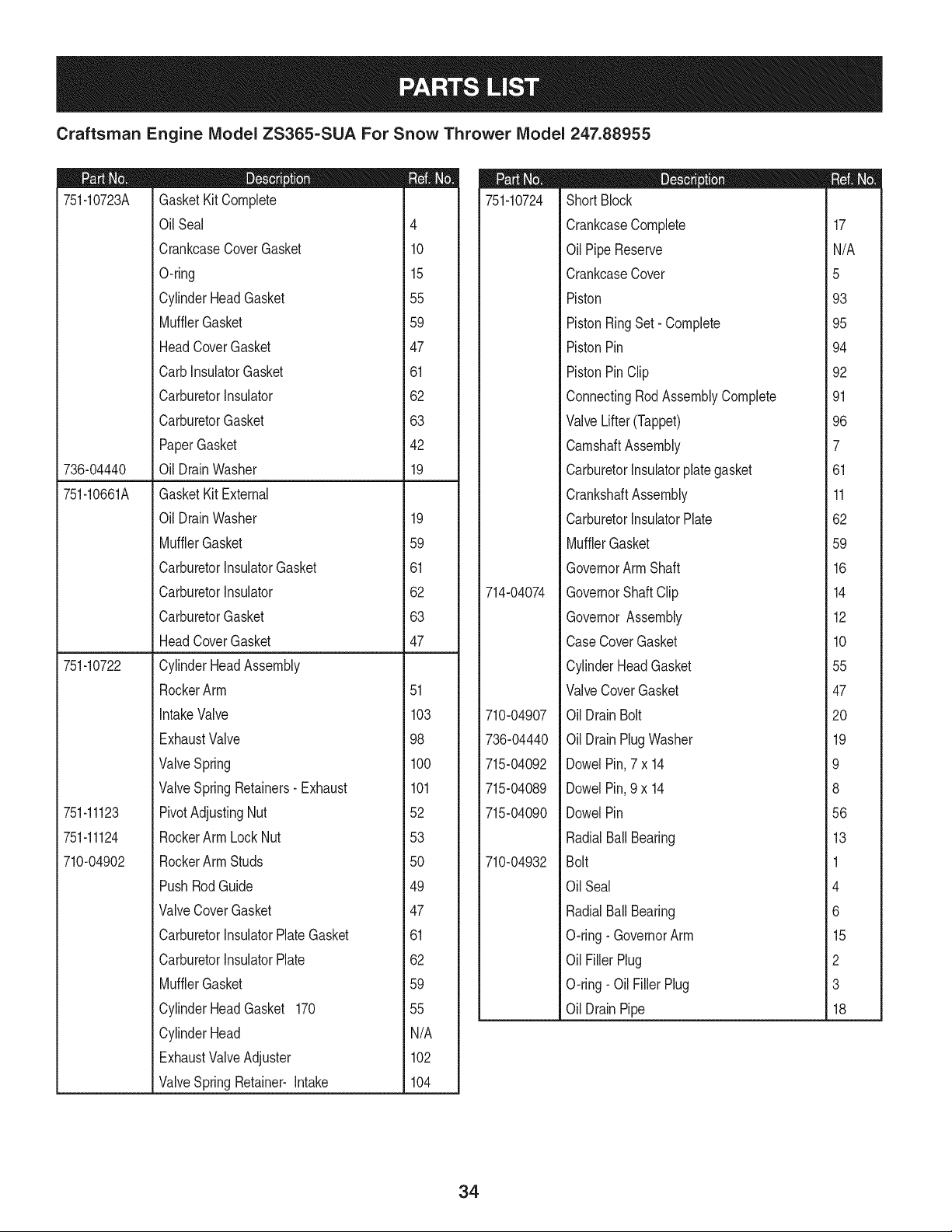
Craftsman Engine IViodel ZS365=SUA For Snow Thrower IViodel 247.88955
751-10723A
736-04440
751-10661A
751-10722
751-11123
751-11124
710-04902
D = O
GasketKitComplete
OilSeal 4
CrankcaseCoverGasket 10
O-ring 15
CylinderHeadGasket 55
MufflerGasket 59
HeadCoverGasket 47
CarbInsulatorGasket 61
CarburetorInsulator 62
CarburetorGasket 63
PaperGasket 42
Oil DrainWasher 19
GasketKit External
Oil DrainWasher 19
MufflerGasket 59
CarburetorInsulatorGasket 61
CarburetorInsulator 62
CarburetorGasket 63
HeadCoverGasket 47
CylinderHeadAssembly
RockerArm 51
IntakeValve 103
ExhaustValve 98
ValveSpring 100
ValveSpringRetainers-Exhaust 101
PivotAdjustingNut 52
RockerArm Lock Nut 53
RockerArm Studs 50
PushRodGuide 49
ValveCoverGasket 47
CarburetorInsulatorPlateGasket 61
CarburetorInsulatorPlate 62
MufflerGasket 59
CylinderHeadGasket 170 55
CylinderHead N/A
ExhaustValveAdjuster 102
ValveSpringRetainer- Intake 104
751-10724
714-04074
710-04907
736-04440
715-04092
715-04089
715-04090
710-04932
D = O
ShortBlock
CrankcaseComplete
OilPipeReserve
CrankcaseCover
Piston
PistonRingSet- Complete
PistonPin
PistonPinClip
ConnectingRodAssemblyComplete
ValveLifter(Tappet)
CamshaftAssembly
CarburetorInsulatorplategasket
CrankshaftAssembly
CarburetorInsulatorPlate
MufflerGasket
GovernorArm Shaft
GovernorShaft Clip
GovernorAssembly
CaseCoverGasket
CylinderHeadGasket
ValveCoverGasket
OilDrainBolt
OilDrainPlugWasher
DowelPin,7 x 14
DowelPin,9 x 14
DowelPin
RadialBallBearing
Bolt
OilSeal
RadialBallBearing
O-ring- GovernorArm
OilFillerPlug
O-ring- Oil FillerPlug
OilDrainPipe
17
N/A
5
93
95
94
92
91
96
7
61
11
62
59
16
14
12
10
55
47
20
19
9
8
56
13
1
4
6
15
2
3
18
34
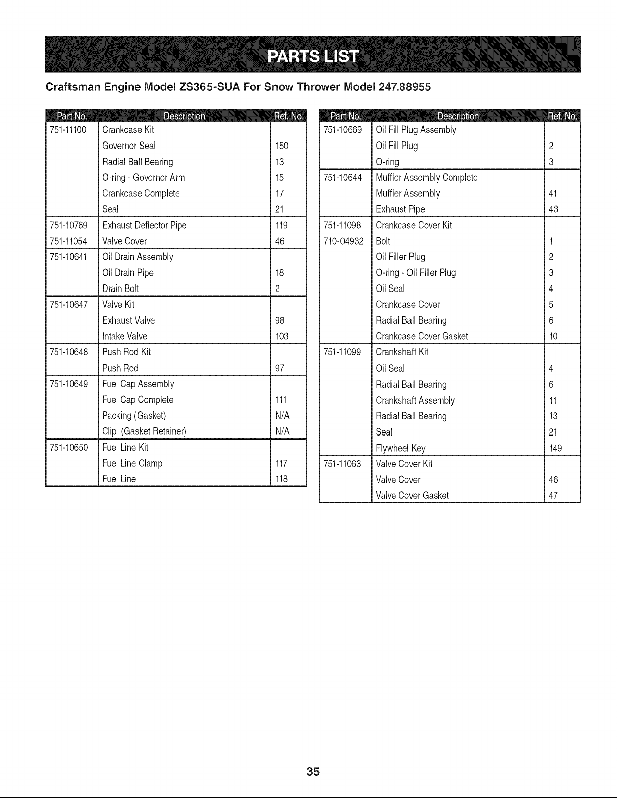
Craftsman Engine IViodel ZS365-SUA For Snow Thrower IViodel 247.88955
|= e e
751-11100 CrankcaseKit
GovernorSeal 150
RadialBallBearing 13
O-ring- GovernorArm 15
CrankcaseComplete 17
Seal 21
751-10769 ExhaustDeflectorPipe 119
751-11054 ValveCover 46
751-10641 Oil DrainAssembly
Oil DrainPipe 18
DrainBolt 2
751-10647 ValveKit
ExhaustValve 98
IntakeValve 103
751-10648 PushRod Kit
PushRod 97
751-10649 FuelCapAssembly
FuelCap Complete 111
Packing(Gasket) N/A
Clip (GasketRetainer) N/A
751-10650 FuelLineKit
FuelLineClamp 117
FuelLine 118
751-10669
751-10644
751-11098
710-04932
751-11099
751-11063
D = 0 0
OilFill PlugAssembly
OilFill Plug 2
O-ring 3
MufflerAssemblyComplete
MufflerAssembly 41
ExhaustPipe 43
CrankcaseCoverKit
Bolt 1
OilFiller Plug 2
O-ring- Oil FillerPlug 3
OilSeal 4
CrankcaseCover 5
RadialBallBearing 6
CrankcaseCoverGasket 10
CrankshaftKit
OilSeal 4
RadialBallBearing 6
CrankshaftAssembly 11
RadialBallBearing 13
Seal 21
FlywheelKey 149
ValveCoverKit
ValveCover 46
ValveCoverGasket 47
35
MTD CONSUMER GROUP INC (MTD), the California Air Resources Board (CARB)
and the United States Environment Protection Agency (U. S. EPA)
Emission Control System Warranty Statement
(Owner's Defect Warranty Rights and Obligations)
EMISSIONCONTROLSYSTEMCOVERAGEIS APPLICABLETOCERTIFIEDENGINESPURCHASEDINCALIFORNIAIN2005ANDTHERE-
AFTER,WHICHARE USEDIN CALIFORNIA,ANDTO CERTIFIEDMODELYEAR2005ANDLATERENGINESWHICHARE PURCHASEDAND
USEDELSEWHEREINTHEUNITEDSTATES.
Californiaandelsewherein the UnitedStatesEmissionControlDefectsWarrantyCoverage
The CaliforniaAir ResourcesBoard(CARB),U. S. EPAandMTDarepleasedto explaintheemissionscontrol systemwarrantyonyour modelyear
2006and latersmalloff-roadengine.In California,new smalloff-roadenginesmustbe designed,builtand equippedto meet theStatesanti-smog
standards.Elsewhereinthe UnitedStates,newnon-road,spark-ignitionenginescertifiedfor model2005and later,mustmeet similarstandardsset
forthby the U. S. EPA.MTDmustwarrantythe emissioncontrolsystemon yourenginefor the periodof timelistedbelow,providedtherehasbeen
noabuse,neglector impropermaintenanceof your smalloff-roadengine.
Youremissioncontrolsystemmay includepartssuch as the carburetor,fuel-injectionsystem,the ignitionsystem,andcatalyticconverter,fuel
tanks,fuel lines,fuel caps,valves,canisters,filters,vaporhoses,clamps,connectors,andotherassociatedemission-relatedcomponents.
Wherea warrantableconditionexists,MTDwill repairyoursmall off-roadengineat no cost to yourincludingdiagnosis,partsand labor.
MANUFACTURER'S WARRANTY COVERAGE:
Thisemissionscontrolsystemis warrantedfor twoyears.If anyemission-relatedpart on yourengine is defective,the part will berepairedor
replacedby MTD.
OWNER'S WARRANTY RESPONSIBILITIES:
As the smalloff-roadengineowner,youare responsibleforthe performanceof the requiredmaintenancelistedinyour Owner'sManual.MTD
recommendsthatyou retainall yourreceiptscoveringmaintenanceson yoursmalloff-roadengine,but MTDcan not denywarrantysolelyfor the
lackof receiptsor foryour failureto ensurethe performanceto allscheduledmaintenance.
As the smalloff-roadengineowner,youshouldhoweverbe awarethat MTDmaydenyyour warrantycoverageif yoursmalloff-roadengineor part
hasfaileddue toabuse,neglect,impropermaintenanceor unapprovedmodifications.
Youare responsiblefor presentingyour smalloff-roadengineto an AuthorizedMTDServiceDealeras soonas a problemexists.Thewarranted
repairsshouldbe completedin a reasonableamountof time,notto exceed30 days.
Ifyou haveanyquestionsregardingyourwarrantyrightsand responsibilities,you shouldcontacta MTDServiceRepresentativeat 1-800-800-7310
andaddressis MTDCONSUMERGROUP,RO.Box361131,ClevelandOH,44136-0019.
DEFECTS WARRANTY REQUIREMENTS FOR 1995 AND LATER SMALL OFF-ROAD ENGINES:
Thissectionappliesto 1995andlater smalloff-roadengines.The warrantyperiodbeginson the datethe engineor equipmentis deliveredto an
ultimatepurchaser.
(a) GeneralEmissionsWarrantyCoverage
MTDmustwarrantto the ultimatepurchaserandeachsubsequentpurchaserthatthe engineis:
(1)Designed,built,andequippedsoas to conformwithallapplicableregulationsadoptedby the Air ResourcesBoardpursuantto its authorityin
Chapters1and 2,Part 5, Division26of the Healthand SafetyCode;and
(2) Freefromdefectsin materialsandworkmanshipthat causethe failureof a warrantedpart to be identicalin all materialrespectsto the partas
describedin theenginemanufacturer'sapplicationfor certificationfora periodof two years.
(b)The warrantyon emissions-relatedpartswill be interpretedas follows:
(1)Anywarrantedpart that is not scheduledfor replacementas requiredmaintenancein the writteninstructionsrequiredby Subsection(c)
mustbewarrantedfor the warrantyperioddefinedinSubsection(a)(2). Ifany such partfails duringthe periodof warrantycoverage,it mustbe
repairedor replacedby MTDaccordingto Subsection(4)below.Anysuch part repairedor replacedunderthewarrantymustbewarrantedfor
the remainingwarrantyperiod.
(2)Any warrantedpartthat is scheduledonlyfor regularinspectioninthe writteninstructionsrequiredby Subsection(c) must bewarrantedfor
thewarrantyperioddefinedin Subsection(a)(2).A statementin such writteninstructionsto the effectof "repairor replaceas necessary"will
not reducethe periodof warrantycoverage.Anysuchpart repairedor replacedunderwarrantymustbe warrantedforthe remainingwarranty
period.
(3) Anywarrantedpartthat whichis scheduledfor replacementas requiredmaintenancein the writteninstructionsrequiredby Subsection(c)
mustbewarrantedfor the periodof timepriorto the first scheduledreplacementpointforthat part.Ifthe part failspriorto thefirst scheduled
replacement,the part mustbe repairedor replacedby MTDaccordingto Subsection(4) below.Any such part repairedor replacedunder
warrantymustbewarrantedfor the remainderof the periodpriorto the first scheduledreplacementpointfor the part.
(4)Repairorreplacementofanywarrantedpartunderthewarrantyprovisionsofthisarticlemustbeperformedatnochargetotheownerata
warrantystation.
(5)NotwithstandingtheprovisionsofSubsection(4)above,warrantyservicesorrepairsmustbeprovidedatallMTDdistributioncentersthat
arefranchisedtoservicethesubjectengines.
(6)Theownermustnotbechargedfordiagnosticlaborthatleadstothedeterminationthatawarrantedpartisinfactdefective,providedthat
suchdiagnosticworkisperformedatawarrantystation.
(7)Theenginemanufacturerisliablefordamagestootherenginecomponentsproximatelycausedbyafailureunderwarrantyofanywarranted
part.
(8)Throughouttheengine'swarrantyperioddefinedinSubsection(a)(2),MTDwillmaintaina supplyofwarrantedpartssufficienttomeetthe
expecteddemandforsuchparts.
(9)Anyreplacementpartmaybeusedintheperformanceofanywarrantymaintenanceorrepairsandmustbeprovidedwithoutchargetothe
owner.SuchusewillnotreducethewarrantyobligationsofMTD.
(10)Add-onormodifiedpartsthatarenotexemptedbytheAirResourcesBoardmaynotbeused.Theuseofanynon-exemptedadd-onor
modifiedpartsshallbegroundsfordisallowingawarrantyclaimmadeinaccordancewiththisarticle.Theenginemanufacturershallnotbe
liableunderthisarticletowarrantfailuresofwarrantedpartscausedbytheuseofnon-exemptedadd-onormodifiedpart.
(c) MTDwill includea copyof the followingemissionwarrantypartslist with each newengine,usingthoseportionsof the listapplicableto the
e__&gine.
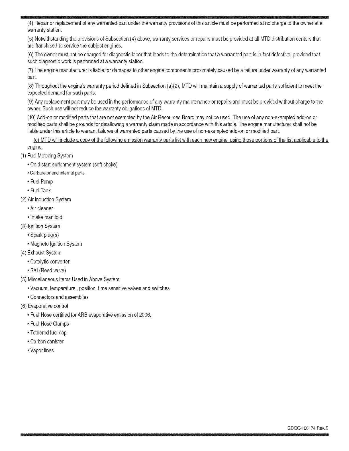
(1)FuelMeteringSystem
• Coldstart enrichmentsystem(soft choke)
,,Carburetorandinternalparts
• Fuel Pump
• FuelTank
(2)Air InductionSystem
• Air cleaner
• Intakemanifold
(3) IgnitionSystem
• Sparkplug(s)
• MagnetoIgnitionSystem
(4)ExhaustSystem
Catalyticconverter
• SAI (Reedvalve)
(5) MiscellaneousItemsUsedin AboveSystem
Vacuum,temperature, position,time sensitivevalvesand switches
Connectorsandassemblies
(6) Evaporativecontrol
• Fuel Hosecertifiedfor ARBevaporativeemissionof 2006.
• Fuel HoseClamps
Tetheredfuel cap
Carboncanister
Vaporlines
GD0C-100174Rev.B
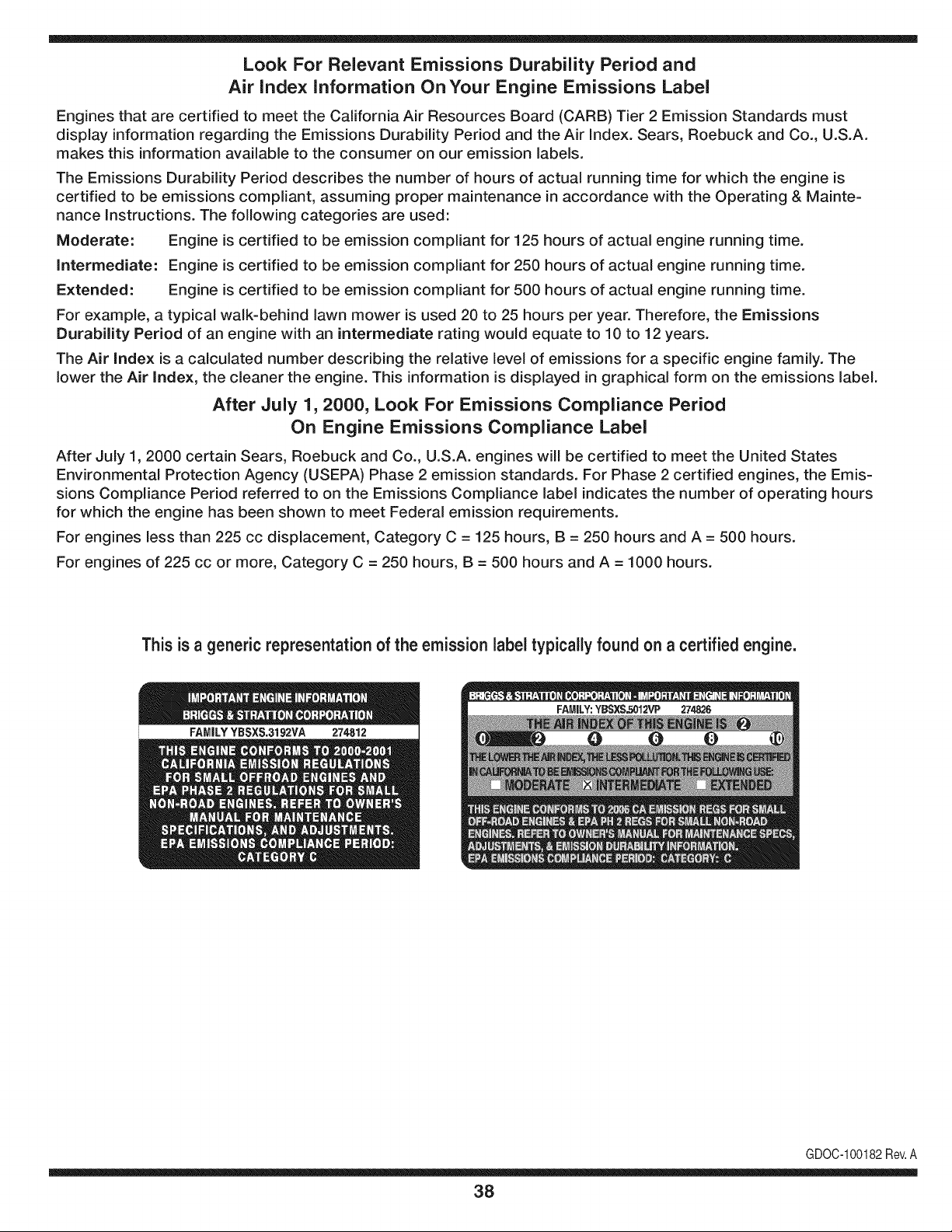
Look For Relevant Emissions Durability Period and
Air index information On Your Engine Emissions Label
Engines that are certified to meet the California Air Resources Board (CARB) Tier 2 Emission Standards must
display information regarding the Emissions Durability Period and the Air Index. Sears, Roebuck and Co., U.S.A.
makes this information available to the consumer on our emission labels.
The Emissions Durability Period describes the number of hours of actual running time for which the engine is
certified to be emissions compliant, assuming proper maintenance in accordance with the Operating & Mainte-
nance Instructions. The following categories are used:
Moderate: Engine is certified to be emission compliant for 125 hours of actual engine running time.
Intermediate: Engine is certified to be emission compliant for 250 hours of actual engine running time.
Extended: Engine is certified to be emission compliant for 500 hours of actual engine running time.
For example, a typical walk-behind lawn mower is used 20 to 25 hours per year. Therefore, the Emissions
Durability Period of an engine with an intermediate rating would equate to 10 to 12 years.
The Air Index is a calculated number describing the relative level of emissions for a specific engine family. The
lower the Air Index, the cleaner the engine. This information is displayed in graphical form on the emissions label.
After July 1,2000, Look For Emissions Compliance Period
On Engine Emissions Compliance Label
After July 1, 2000 certain Sears, Roebuck and Co., U.S.A. engines will be certified to meet the United States
Environmental Protection Agency (USEPA) Phase 2 emission standards. For Phase 2 certified engines, the Emis-
sions Compliance Period referred to on the Emissions Compliance label indicates the number of operating hours
for which the engine has been shown to meet Federal emission requirements.
For engines less than 225 cc displacement, Category C = 125 hours, B = 250 hours and A = 500 hours.
For engines of 225 cc or more, Category C = 250 hours, B = 500 hours and A = 1000 hours.
This is a generic representation of the emission label typically found on a certified engine.
FAMILYYBSXS.3192VA 274812
GDOC-100182Rev.A
38
Congratulationson makinga smart purchase.YournewCraftsman®
productis designedandmanufacturedfor yearsof dependableopera-
tion.But likeall products,it mayrequirerepairfromtimeto time.That's
whenhavinga RepairProtectionAgreementcan saveyoumoneyand
aggravation.
Here'swhatthe RepairProtectionAgreement*includes:
* Expert service byour 10,000professionalrepairspecialists
* Unlimited service and no charge for partsand laboronall
coveredrepairs
* Product replacement up to $1500ifyourcoveredproductcan't be
fixed
* Discountof 10%from regularpriceof serviceand relatedinstalled
partsnotcoveredby theagreement;also,10%off regularpriceof
preventivemaintenancecheck
* Fast help by phone- we call itRapidResolution- phonesupport
froma Searsrepresentative.Thinkof usas a "talkingowner's
manual."
Once youpurchasethe Agreement,a simplephonecall isall thatit
takesfor youto scheduleservice.Youcan call anytimedayor night,or
schedulea serviceappointmentonline.
The RepairProtectionAgreementisa risk-freepurchase.Ifyou cancel
for any reasonduringthe productwarrantyperiod,wewill providea full
refund.Or,a proratedrefundanytimeafter the productwarrantyperiod
expires.Purchaseyour RepairProtectionAgreementtoday!
Some limitations and exclusionsapply. For prices and additional
informationin the U.S.A. call 1-800-827-8855.
*Coverage in Canadavaries on some items.For full details call
Sears Canada at 1-800-381-8665.
Sears Installation Service
ForSearsprofessionalinstallationof homeappliances,garagedoor
openers,waterheaters,and othermajorhomeitems,in the U.S.A.or
Canadacall 1-800-4-MY-HOME®.
39
Declaraci6n de garantia ............................ Pagina 39
Practicas operaci6n seguras ..................... Pagina 40
Montaje ...................................................... Pagina 44
Operaci6n .................................................. Pagina 48
Servicio y Mantenimiento .......................... Pagina 52
Almacenamiento fuera de temporada ....... Pagina 60
Soluci6n de problemas .............................. Pagina 61
Acuerdo de protecci6n para reparaciones .... Pagina 65
Etiquetas de seguridad .............................. Pagina 7
Lista de piezas ........................................... Pagina 26
NOmero de servicio ................................... Cubierta
posterior
GARANTiA LIMITADA CRAFTSMAN
Dos Ahos en Lanzador de Nieve
Cuandohechofuncionary mantenidosegOntodaslas instruccionessuministradas,si estelanzadorde nievefalla debidoa un defectoen mate-
rialo habilidaddentrode dosa_osde la fechao compra,vueltaello a algunaposici6nde bajadade Craftsmanautorizadaparala reparaci6n
libre.Paralaposici6nautorizadam_scercana,Ilame1-800-4MYHOME.
Estagaranfias61otendr_validezdurante90 dias si este productose utilizaen cualquiermomentopara fines comercialeso de alquiler.
Esta garantiacubreSOLOdefectos en material y habilidad.Sears no pagar_para:
• Losarficulosprescindiblesque se hacenIlevadospuestosduranteel uso normal,incluso,perono limitadosparapatinarzapatos,platode
afeitado,esquilanalfileres,buj[a,filtrodeaire,cinturones,y filtro del aceite.
• Revisi6ndemantenimientoest_ndar,cambiosde aceite,o puestasa punto.
• Reemplazode neum_ticoo reparaci6ncausadaporpinchazosdesdefuerade objetos,como u_as,espinas,tocones,o cristal.
• Neum_ticoo reemplazode ruedao reparaci6nqueresultade ropanormal,accidente,u operaci6nimpropiao mantenimiento.
• Las reparacionesnecesariasdebidoal abusodeoperador,inclusoperono limitadoparada_arcausadoafectandoobjetosque doblanel
marcoo el cigOe_al,o el sobreexcesode velocidaddel motor.
• Reparacionesnecesariasdebidoa negligenciadel operador,incluyendoentre otros,da_osmec_nicoy el_ctricoocasionadopor un
almacenamientonoapropiado,falla por el usode aceitede grado y/o cantidadnoapropiadao fallapor no darmantenimientoal equipode
acuerdocon las instruccionescontenidasen el manualdel operador.
• Limpiezao reparacionesal motor(sistemadecombustible)provocadaspor un combustiblecontaminadouoxidado(viejo).En general,el
combustibledebeutilizarseen un perbdo no mayorde 30d[as a partirde su adquisici6n.
• Elempejoramientonormaly la ropade losfinesexteriores,o productoetiquetanel reemplazo.
Estagaranfias61otendrAvalidezmientrasel productose utiliceen los EstadosUnidos.
Estagaranfialeotorgaderechoslegalesespedficos,pero ustedpodr[agozarde otros derechosen raz6nde su lugarde residencia.
Sears, Roebuck and Co., HoffmanEstates, IL 60179
Tipode aceitedelmotor:
Capacidaddeaceitedel motor:
Capacidaddecombustible:
Bujfas:
Separaci6nde lasbujias:
5W-30
20 onzas
2.3 cuartos
Torch F6RTC (F6TC)
.020" a .030"
N_merode modelo ..........................................................
N_merode serie ..............................................................
Fechade compra .............................................................
Registrearriba el nOmerodel modelo,el nOmerode seriey la fecha
decompra
© Sears Brands,LLC
40
Lapresenciadeeste sirnboloindicaque setrata de instrucciones
irnportantesde seguridadquese debenrespetarparaevitar
poneren peligrosu seguridadpersonaly/o materialy lade otras
personas.Lea y siga todaslas instruccionesde este manualantes
de poneren funcionarnientoesta rn_.quina.Si no respetaestas
instruccionespodria provocarlesionespersonales.Cuandoveaeste
sirnbolo,ipresteatenci6na la advertencia!
PROPOSICI6N 65 DE CALIFORNIA
Elescapedel motordeeste producto,algunosde suscornponentes
y algunoscornponentesdel vehiculocontieneno liberan sustancias
quirnicasqueel estado de Californiaconsideraque puedenproducir
c_.ncer,defectosde nacirnientou otros problernasreproductivos.
Estarn_.quinarue construidapara seroperadade acuerdocon
las reglasde seguridadcontenidasen este manual.AI igualque
concualquiertipo deequipornotorizado,undescuidoo errorpor
partedeloperadorpuedeproducirlesionesgraves.Esta rn_.quina
es capazde arnputarrnanosy piesy dearrojarobjetoscon gran
fuerza.Deno respetarlas instruccionesde seguridadsiguientesse
puedenproducirlesionesgraveso larnuerte.
Su responsabilidad--Restrinja el usode esta rn_.quina
rnotorizadaa las personasque lean,cornprendany respetenlas
advertenciase instruccionesqueaparecenen estemanualy en la
rn_.quina.
iGI.IARI)E ESTASINSTRUCCIONES!
CAPACITACION
• Lea,entienday curnplatodaslas instruccionesincluidasen
la rn_.quinay enlos rnanualesantesde rnontarlay utilizarla.
Guardeestemanualen un lugarseguroparaconsultasfuturasy
peri6dicas,asi cornopara solicitarrepuestos.
• Leael ManualdelOperadory sigatodas las advertenciase
instruccionesde seguridad.Elfracasode hacerasi puedecausar
la heridaseriaal operadory/o personaspresentes.ParaIlarnada
depreguntas,1-800-659-5917.
• Farniliaricesecontodoslos controlesy con el usoadecuado
delos rnisrnos.Sepac6rnodetenerlarn_.quinay desactivarlos
controlesr_.pidarnente.
• No perrnitanuncaque los ni_osrnenoresde 14a_osutilicen
estarn_.quina.Los ni_osde 14a_osen adelantedeben leer y
entenderlas instruccionesde operaci6ny norrnasde seguridad
contenidasen este manual,y en la rn_.quinaydebenser entrena-
dosy supervisadospor un adulto.
• Nuncaperrnitaquelos adultosoperenestarn_.quinasin recibir
antesla instrucci6napropiada.
• Losobjetosarrojadosporla rn_.quinapuedenproducirlesiones
graves.Planifiqueel patr6nen el que va air arrojandonievepara
evitarque ladescargade materialse realicehacialos carninos,
los observadores,etc.
• Mantengaa losobservadores,ayudantes,rnascotasy ni_ospor
Io rnenosa 75 piesde la rn_.quinarnientrasla rnisrnaest,.en
funcionarniento.Detengala rn_.quinasi alguienseacerca.
• Seaprecavidoparaevitarpatinarseo caerseespecialrnente
cuandoopera la rn_.quinaen reversa.
PR E PA RATIVO S
Inspeccionerninuciosarnenteel_.readondeutilizar_,el equipo.Saque
todoslos felpudos,peri6dicos,trineos,tablas,cablesy otros objetos
extra_oscon los que podriatropezaro que podrianser arrojadospor
labarrena/irnpulsor.
• Paraprotegerselosojos utilicesiernpreanteojoso antiparras
de seguridadrnientrasopera la rn_.quinao rnientrasla ajusta
o repara.Losobjetosarrojadosquerebotanpuedenproducir
lesionesocularesgraves.
• Noopere la rn_.quinasin la vestirnentaadecuadaparaestaral
airelibreen invierno.No utilicealhajas,bufandaslargasu otras
prendassueltasque podrianenredarseen las partesrn6viles.
Utiliceun calzadoespecialparasuperficiesresbaladizas.
• Useun prolongadory un tornacorrientede tres cables con
conexi6na tierraparatodaslas rn_.quinascon rnotoresde
encendidoel_ctrico.
• Ajustelaalturade lacaja del tornacorrientepara lirnpiarla grava
o las superficiescon piedrastrituradas.
• Desengranetodaslas palancasde controlantesde arrancarel
motor.
• Nuncaintenterealizarajustesrnientrasel motorest,. en rnarcha
exceptoen los casosespecificarnenterecornendadosen el
manualdeloperador.
• Dejeque el motor y la rn_.quinase adaptena laternperatura
exteriorantesde cornenzara sacarla nieve.
41
Manejo seguro de la gasolina
Paraevitarlesionespersonales0 daSosrnaterialestengarnucho
cuidadocuandotrabajecon gasolina.Lagasolinaes surnarnente
inflarnabley susvaporespuedencausarexplosiones.Si se derrarna
gasolinaencirna0 sobrela ropase puedelesionargravernenteya que
se puedeincendiar. L&vesela piel y c&rnbiesede ropade inrnediato.
• Utilices610los recipientesparagasolinaautorizados.
• Apaguetodoslos cigarrillos,cigarros,pipasy otrasfuentesde
cornbusfi6n.
• Nuncacarguecombustibleen larn&quinaen unespaciocerrado.
• Nuncasaquela tapadelcombustibleniagreguecombustible
rnientrasel motorest&caliente0 en rnarcha.
• Dejequeel motorse enfriepor I0 rnenosdos rninutosantesde
volvera cargarcombustible.
• NuncaIleneenexcesoel dep6sitodecombustible.Lleneel
tanquea no rn&sde1/2pulgadapordebajode la basedelcuello
de Ilenadodejandoespaciopara la dilataci6ndeIcombustible.
• Vuelvaa colocarla tapade lagasoiinay aj_stelabien.
• Lirnpieel combustiblequese hayaderrarnadosobreel motory el
equipo.Trasladela rn&quinaa otra zona. Espere5 rninutosantes
deencenderel motor.
• Nuncaalrnacenela rn&quina0 el recipientede combustibleen
unespaciocerradodonde hayafuego,chispas0 luz piloto(por
ejernplo,hornos,calentadoresdeagua,calefactores,secadores
de ropa,etc.).
• Dejequela rn_.quinase enfrieporIo rnenos5 rninutosantesde
guardarla.
• NuncaIlenelos recipientesenel interiorde un vehiculoo carni6n
ocaja de rernolquecon recubrirnientospl_.sticos.Coloque
siernprelos recipientesenel pisoy lejosdel vehiculoantesde
Ilenarlos.
• Sies posible,retireel equipoa gasolinadelcarni6no rernolque
y II_neloen el suelo.Si esto no es posible,Ileneel equipoen un
rernolquecon contenedorport_.til,en vez de desdeunaboquilla
dispensadorade gasolina.
• Mantengala boquilladispensadoraen contactocon el hordedel
dep6sitode combustibleo con la aberturadel recipienteen todo
rnornento,hastaterrninarla carga. No utiliceundispositivode
apertura/cierrede boquilla.
FUNCIONANIIENTO
• No pongalas rnanoso los piescerca de las piezasrotatorias,
en lacajade la barrena/ irnpulsoro en el rnontajedelcanalde
descarga.Hacercontactocon piezasgiratoriaspuederesultaren
laarnputaci6ndernanoso pies.
• La palancadecontrolde la barrena/ irnpulsores un dispositivo
de seguridad.Nuncaevitesu funcionarniento.De hacerlola
operaci6nde la rn_.quinaes riesgosay puedeocasionarlesiones.
• Las palancasde control debenfuncionarbien en arnbasdirec-
cionesy regresarautorn_.ticarnentea la posici6nde desengrane
cuandose lassuelta.
• Nuncaoperela rn_.quinasi falta un rnontajedelcanalo si el
rnisrnoest,.daSado.Mantengatodoslosdispositivosde seguri-
daden su lugaryen funcionarniento.
• Nuncaenciendael motor en espacioscerradoso en una zona
con pocaventilaci6n.El escapedel motorcontienernon6xidode
carbono,ungas inodoroy letal.
• Noutilice la rn_.quinabajo la influenciadel alcoholo las drogas.
• El silenciadory el motorse calientany puedencausarquernadu-
ras.Nolos toque. Mantengaa los niSosalejados.
• Seasurnarnenteprecavidocuandooperela rn_.quinasobreuna
superficiecon gravaocuandola cruce.Mant_ngasealerta por si
se presentanpeligrosocultoso tr_.nsito.
• Tengacuidadocuandocarnbiede direcci6no cuandoopere la
rn_.quinaen pendientes.
• Planifiqueel patr6nen el que va air arrojandonieveparaevitar
que ladescargade materialse produzcahacialas ventanas,
las paredes,losautorn6viles,etc.y evitarasi posiblesdaSos
rnaterialeso lesionesproducidasporlos rebotes.
• Nuncadirija la descargahacialos niSos,los observadoreso las
rnascotasni dejequenadiese paredelantede la rn_.quina.
• Nosobrecarguela capacidadde la rn_.quinatratandode sacarla
nievernuyr_.pidarnente.
• Nuncaopereesta rn_.quinasin buenavisibilidado ilurninaci6n.
Siernpredebeestar segurode que est,. bien afirrnadoy su-
jetandofirrnernentelas rnanijas.Carnine,nuncacorra.
• Cortela corrientea la barrena/ irnpulsorcuandotransportela
rn_.quinao cuandola rnisrnano est,. en uso.
• Nuncaoperela rn_.quinaaalta velocidadde desplazarniento
sobresuperficiesresbaladizas.Mirehaciaabajoy haciaatr_.sy
tengacuidadocuandovaya rnarchaatr_.s.
• Si la rn_.quinacornenzaraa vibrarde rnaneraanorrnal,detengael
motor,desconecteel cablede labujia y p6ngalade rnaneraque
hagarnasacontra el motor.Inspeccionela rn_.quinarninuciosa-
rnenteparaver si est,.daSada.Reparetodoslos daSosantesde
encendery operarla rn_.quina.
• Desengranetodas las palancasde controly detengael motor
antesde dejar la posici6nde operaci6n(detr_.sde las rnanijas).
Espereaque la barrena/ irnpulsorse detengaporcornpleto
antesde destaparel rnontajedel canalo realizarajustese
inspecciones.
• Nuncapongalas rnanosenlas aberturasdedescargao de
recolecci6n.Utilicesiernprela herrarnientadelirnpiezaquese
adjuntaparadestaparla aberturade descarga.Nodestapeel
rnontajedelcanal rnientrasel motorest,.en funcionarniento.
Antesde destaparlo,apagueel motory perrnanezcadetr_.sde las
rnanijashastaque todaslas partesrn6vilesse hayandetenido.
• Uses61ounionesy accesoriosaprobadosporel fabricante(por
ejernplo,pesasparalas ruedas,cadenasparalos neurn_.ticos,
cabinas,etc.).
42
• Paraencenderel motor,jale de la cuerdalentarnentehasta que
sientaresistencia,luegojale r_.pidarnente.Elreplieguer_.pidode
la cuerdade arranque(tensi6nde retroceso)le jalar_,la rnanoy
el brazohaciael motorrn_.sr_.pidodeIo que usted puedesoltar.
El resultadopuedenserhuesosrotos,fracturas,hernatornaso
esguinces.
• Si se presentansituacionesque no est_.nprevistasen este
manual,seacuidadosoy use el sentidocornOn.P6ngaseen
contactocon Asistenciaal Clientepara solicitarayuday el
nornbredeldistribuidorde serviciorn_.scercano.
MANTENIMIENTO Y ALMACENAMIENTO
• Nuncaalterelos dispositivosde seguridad.Controleperi6dica-
rnentequefuncionencorrectarnente.Rernitasealas secciones
demantenirnientoy ajustede estemanual.
• Antesde realizarla lirnpieza,repararo revisarla rn_.quina,
desengranetodas laspalancasde controly detengael motor.
Esperea quela barrena/ irnpulsorse detengaporcornpleto.
Desconecteel cablede la bujfay p6ngalohaciendornasacontra
el motorparaevitarquese enciendaaccidentalrnente.
• Controlefrecuenternentequetodoslospernosy tornillosest_n
bienajustadosparacornprobarquela rn_.quinase encuentra
encondicionessegurasde funcionarniento.Adern_.s,hagauna
inspecci6nvisual de la rn_.quinaparaverificarsi est,.da_ada.
• No carnbiela configuraci6ndel reguladordel motorni acelere
dernasiadoel rnisrno.El reguladordel motorcontrolala velocidad
rn_.xirnaseguradefuncionarnientodelmotor.
• Las placasde raspadoy las zapatasantideslizantesquese
usancon la rn_.quinaquitanievese desgastany se da_an.
Paraprotegersu seguridad,verifiquefrecuenternentetodos los
cornponentesy reernpl_.celoss61ocon partesde los fabricantes
deequiposoriginales(OEM)."i Elusode piezasquenocurnplen
con lasespecificacionesdel equipooriginalpuederesultaren
rendirnientoinadecuadoadern_.sde poneren riesgola seguri-
dad!"
• Reviselas palancasde controlperi6dicarnentepara verificar
queengraneny desengranenadecuadarnentey ajOstelossi es
necesario.Consultela secci6nde ajustesde este manualdel
operadorparaobtenerinstrucciones.
• Mantengao reernplacelasetiquetasde seguridade instrucciones
segQnseanecesario.
• Respetelas norrnasreferentesa ladisposici6ncorrectay las
reglarnentacionessobregasolina,aceite,etc. para protegerel
medicarnbiente.
• Antesdealrnacenarlarn_.quinaenci_ndalaunosrninutospara
sacarla nievequehayaquedadoen la rnisrnay paraevitarasi
quese congelela barrena/irnpulsor.
• SegOnla Cornisi6nde Seguridadde Productosparael Consu-
rnidorde los EstadosUnidos(CPSC)y la Agenciade Protecci6n
Arnbientalde los EstadosUnidos(EPA),esteproductotieneuna
vida Qtilmediade siete (7) a_os,660 horasdefuncionarniento.
AI finalizarlavida Otilmedia,adquierauna rn_.quinanuevao
hagainspeccionaranualrnente_sta por un distribuidorde servicio
autorizadoparacerciorarsede quetodoslos sisternasrnec_.nicos
y deseguridadfuncionancorrectarnentey no tienenexcesivo
desgaste.Si no Iohace,puedenproducirseaccidentes,lesiones
o rnuerte
• Nuncaalrnacenela rn_.quinao el recipientede combustibleen un
espaciocerradodondehayafuego,chispaso luz pilotocornopor
ejernplo,calentadoresde agua,hornos,secadoresde ropa,etc.
• Consultesiernpreel manualdel operadorparaobtener
instruccionesadecuadasparael alrnacenarnientofuerade
ternporadaVerifiquefrecuenternentelaIfneade combustible,el
tanque,el tap6n,y losaccesoriosbuscandorajaduraso perdidas.
Reernplacede ser necesario.
• Nod_ arranqueal motorsi noest,. labujiade encendido.
NO MODIFIQUE EL MOTOR
Paraevitarlesionesgraveso larnuerte,no rnodifiqueel motorbajo
ningunacircunstancia.Si carnbiala configuraci6ndel reguladorel
motorpuededescontrolarsey operara velocidadesinseguras.Nunca
carnbielaconfiguraci6ndef_.bricadel reguladordel motor.
AVISO REFERIDO A EMISIONES
Losrnotoresqueest&ncertificadosy curnplencon las regulaciones
de ernisionesfederalesEPAy de Californiapara SORE(Equipos
peque_ostodoterreno)est_.ncertificadosparaoperarcon gasolina
cornOnsinplornoy puedenincluirlossiguientessisternasde control
de ernisiones:Modificaci6nde motor(EM) y catalizadorde tresvias
(TWO)si est_.nequipadosde esa rnanera.
GUARDACHISPAS
Estarn&quinaest,. equipadacon unmotorde cornbusti6ninternay
nodebe ser utilizadaen o cercade unterrenoagrestecubiertopor
bosque,rnalezaso hierba exceptosi el sisternade escapedel motor
est,.equipadocon unarnortiguadorde chispasquecurnplaconlas
leyeslocaleso estatalescorrespondientes,en caso de haberlas.
Sise utilizaun arnortiguadorde chispasel operadorIo debernantener
en condicionesde usoadecuadas.Enel Estadode Californialas
rnedidasanteriorrnenternencionadassonexigidaspor ley (Arficulo
4442del C6digode RecursosPOblicosde California).Es posible
queexistanleyessirnilaresenotros estados.Lasleyesfederalesse
aplicanenterritoriosfederales.
Puedeconseguirelarnortiguadorde chispasparael silenciadora
travesde sudistribuidorautorizadode rnotoreso poni_ndoseen
contactocon eldepartarnentodeservicios.
43
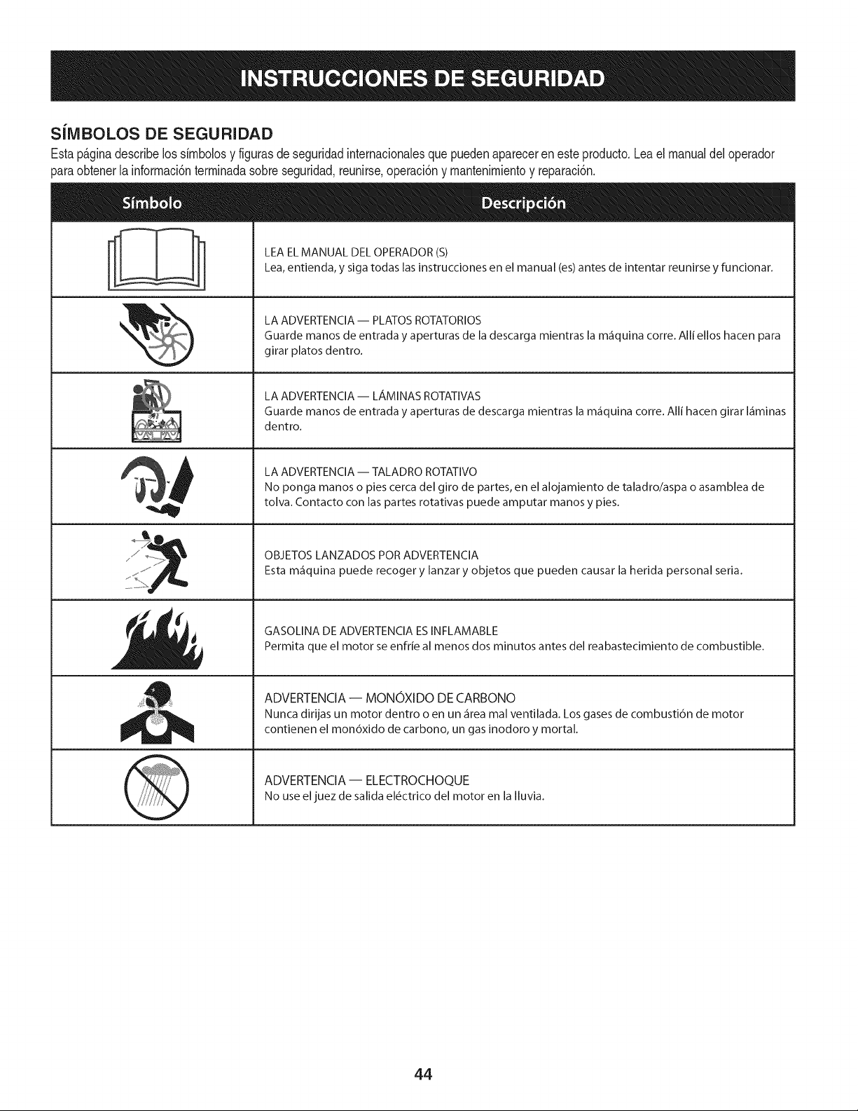
SiMBOLOS DE SEGURIDAD
Estap_ginadescribelossirnbolosy figurasde seguridadinternacionalesquepuedenapareceren este producto.Lea el manualdel operador
)araobtenerla inforrnaci6nterrninadasobreseguridad,reunirse,operaci6ny rnantenimientoy reparaci6n.
i
i
LEAELMANUAL DELOPERADOR(S)
Lea,entienda, y siga todas lasinstrucciones en el manual (es)antes de intentar reunirse y funcionar.
LA ADVERTENCIA -- PLATOS ROTATORIOS
Guarde manos de entrada y aperturas de la descarga mientras la m_iquina corre. Alli ellos hacen para
girar platos dentro.
LA ADVERTENCIA-- LAMINAS ROTATIVAS
Guarde manos de entrada y aperturas de descarga mientras la m_iquina corre. Alli hacen girar I_iminas
dentro.
LA ADVERTENCIA -- TALADRO ROTATIVO
No ponga manos o pies cerca del giro de partes, en el alojamiento de taladro/aspa o asamblea de
tolva. Contacto con las partes rotativas puede amputar manos y pies.
OBJETOS LANZADOS POR ADVERTENCIA
Esta m_iquina puede recoger y lanzar y objetos que pueden causar la herida personal seria.
GASOLINA DE ADVERTENCIA ESINFLAMABLE
Permita que el motor se enfrie al menos dos minutos antes del reabastecimiento de combustible.
ADVERTENCIA -- MONOXIDO DE CARBONO
Nunca dirijas un motor dentro o en un _irea mal ventilada. Los gases de combusti6n de motor
contienen el mon6xido de carbono, un gas inodoro y mortal.
ADVERTENCIA- ELECTROCHOQUE
No use eljuez de salida el_ctrico del motor en la Iluvia.
44
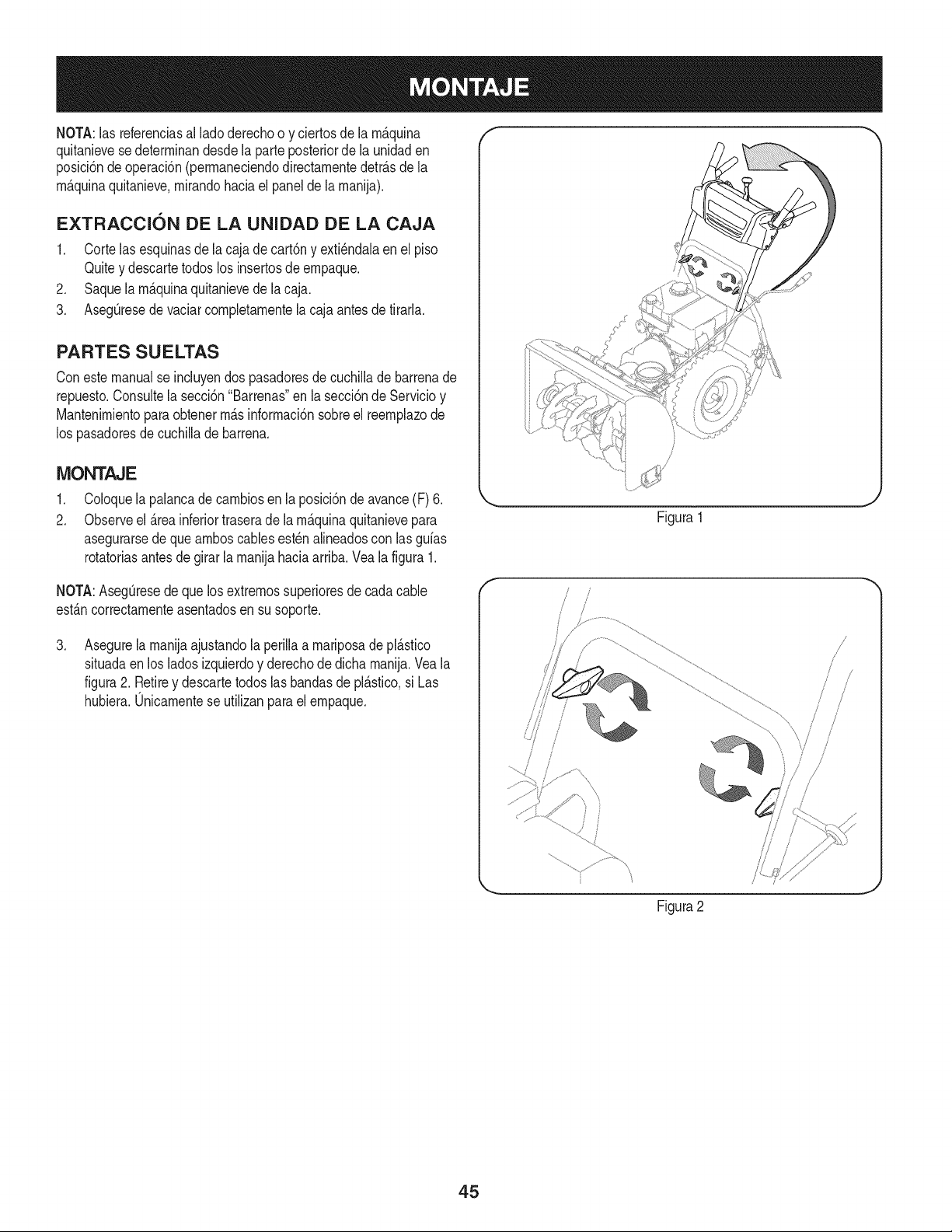
NOTA:las referenciasal lado derechoo y ciertosde la rn_.quina
quitanievesedeterrninandesdela parteposteriorde la unidaden
posici6ndeoperaci6n(perrnaneciendodirectarnentedetr_.sde la
rn_.quinaquitanieve,rnirandohaciael panelde la rnanija).
EXTRACCI6N DE LA UNIDAD DE LA CAJA
1. Corte lasesquinasde la cajade cart6ny exti_ndalaen el piso
Quitey descartetodoslos insertosde ernpaque.
2. Saquela rn_.quinaquitanievede la caja.
3. AsegQresede vaciarcornpletarnentela cajaantesde tirarla.
PARTES SU ELTAS
Conestemanualse incluyendos pasadoresde cuchiNade barrenade
repuesto.Consultela secci6n"Barrenas"en lasecci6ndeServicioy
Mantenirnientopara obtenerrn_.sinforrnaci6nsobreel reernplazode
los pasadoresde cuchillade barrena.
MONTAJE
,
2.
Coloquela palancade carnbiosen la posici6nde avance(F) 6.
Observeel _.reainferiortraserade la rn_.quinaquitanievepara
asegurarsede quearnboscablesest_n alineadoscon las gufas
rotatoriasantes de girar la rnanijahaciaarriba.Vea la figura1.
NOTA:AsegQresede quelosextrernossuperioresde cadacable
est_.ncorrectarnenteasentadosen susoporte.
,
Asegurela rnanijaajustandolaperilla a rnariposadepl_.stico
situadaen los ladosizquierdoy derechodedicha rnanija.Veala
figura2. Retirey descartetodoslasbandasde pl_.stico,si Las
hubiera.Unicarnentese utilizanparael ernpaque.
\
Figura1
f
Figura2
!
/
/
/
45
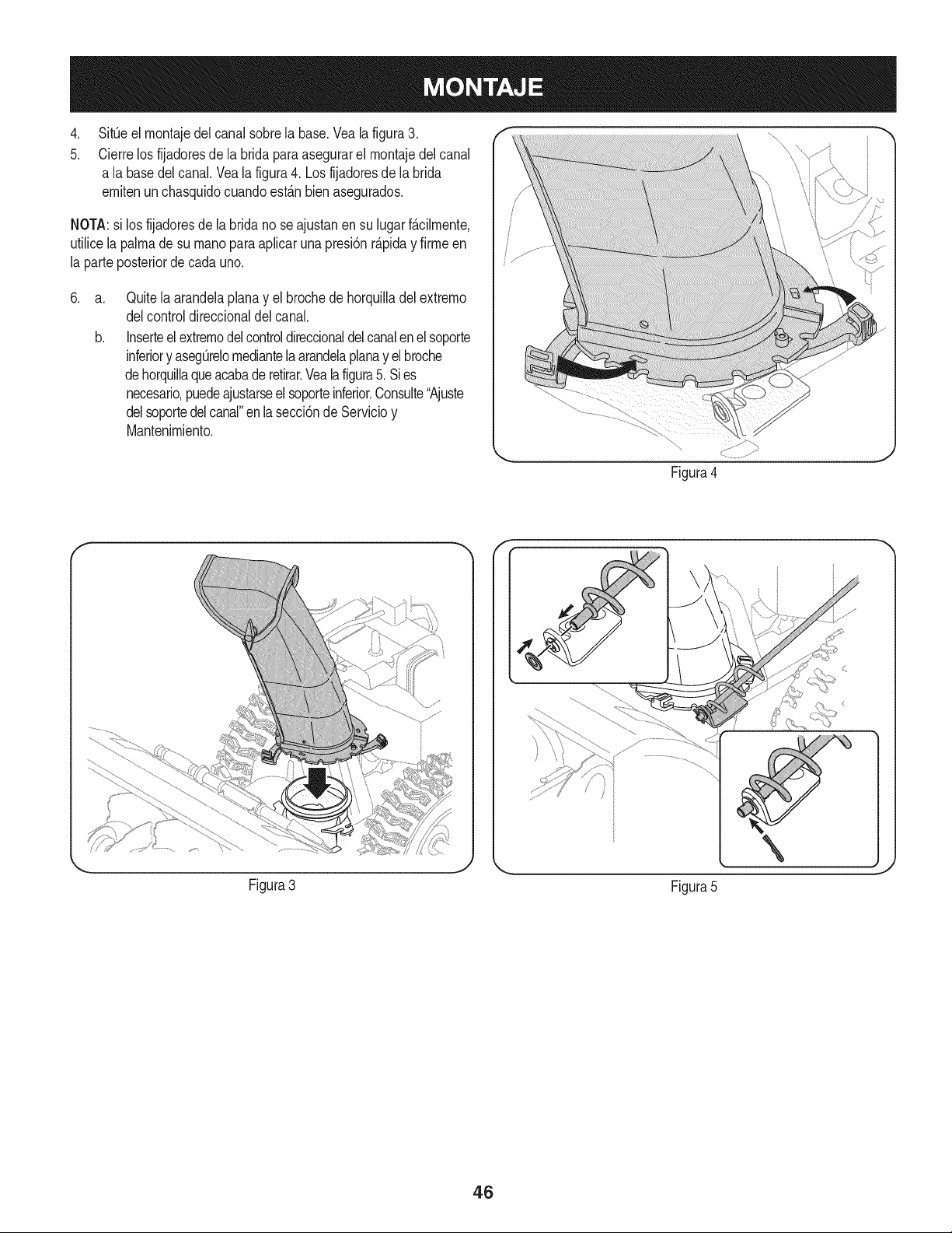
.
5.
SitOeel montajedel canalsobrela base.Vea la figura3.
Cierrelos fijadoresde la bridapara asegurarel montajedelcanal
a la basedelcanal.Veala figura4. Losfijadoresde la brida
emitenun chasquidocuandoest_.nbienasegurados.
NOTA:si los fijadoresde labridano seajustanen su lugarf_.cilmente,
utilicelapalmade su rnanopara apfcar una presi6nr_.piday firmeen
la parteposteriorde cadauno.
.
a.
b.
Quitela arandelaplanay el brochede horquiladel extremo
delcontroldireccionaldel canal.
Inserteel extremodel controldireccionaldel canalenel soporte
inferiory asegOrelomediantela arandelaplanay elbroche
dehorquilaqueacabade retirar.Veala figura5. Si es
necesario,puedeajustarseel soporteinferior.Consute"Ajuste
delsoportedelcanal"en la secci6nde Servicioy
Mantenimiento.
Figura4
Figura3
Figura5
46
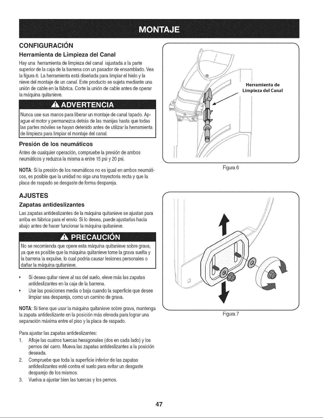
CONFIGURACION "_ "
Herramienta de Limpieza del Canal
Hayuna herramientade limpiezadel canal iajustadaa la parte
superiorde lacaja dela barrenacon un pasadorde ensamNado.Vea
lafigura6. Laherramientaest,. diseSadaparalimpiarel hieloy la
nievedelmontajede un canal.Esteproductose sujetamedianteuna
uni6nde cableen laf_.brica.Cortela uni6n de cableantes de operar
la mAquinaquitanieve.
Nuncausesus manosparaliberarunmontajede canaltapado.Ap-
agueel motory permanezcadetr_.sde las manijashastaquetodas
las partes m6vilesse hayandetenidoantesde utilizarla herramienta
de limpiezaparalimpiarel montajedelcanal.
Presi6n de los neumaticos
Antesde cualquieroperaci6n,compruebela presi6nde ambos
neumAticosy reduzcalamismaa entre15psiy 20psi.
NOTA:Sila presbn de los neum_.ticosno es igualen ambosneum_.ti-
cos,es posiNequela unidadno siga unatrayectoriarectay quela
placade raspadose desgastede formadespareja.
Herrarnienta de
Lira _iezadel Canal
Figura6
AJUSTES
Zapatas antideslizantes
Laszapatasantideslizantesde la m_.quinaquitanieveseajustan para
arribaen f_.bricaparaelenvio.Si Iodesea,puedeajustarlashacia
abajoantesde hacerfuncionarla m_.quinaquitanieve.
lNo se queopere m_.quinaquitanieve grava,
recomienda esta sobre
ya que es posiblequela m_.quinaquitanievetome la gravasueltay
la barrenalaexpulse,Io cual podriacausarlesionespersonaleso
daSarla m_.quinaquitanieve.
• Sideseaquitarnieveal rasdel suelo,elevem_.slaszapatas
antideslizantesenla cajade la barrena.
• Uselas posicionesmediao bajacuandola superficieque desee
limpiarseadespareja,comouncaminodegrava.
NOTA:Sitienequeusar la m&quinaquitanievesobregrava,mantenga
lazapataantideslizanteen la posici6nm_.selevadapara Iograruna
separaci6nm&ximaentreel pisoy la placade raspado.
f
Figura7
Paraajustarlaszapatasantideslizantes:
1. Aflojelas cuatrostuercashexagonales(dosencada lado)y los
pernosdel carro.Muevalas zapatasantideslizantesa la posici6n
deseada.
2. Compruebeque toda la superficieinferiorde laszapatas
antideslizantesest_contrael sueloparaevitar un desgaste
desparejode los mismos.
3. Vuelvaa ajustarbien lastuercasy lospernos.
47
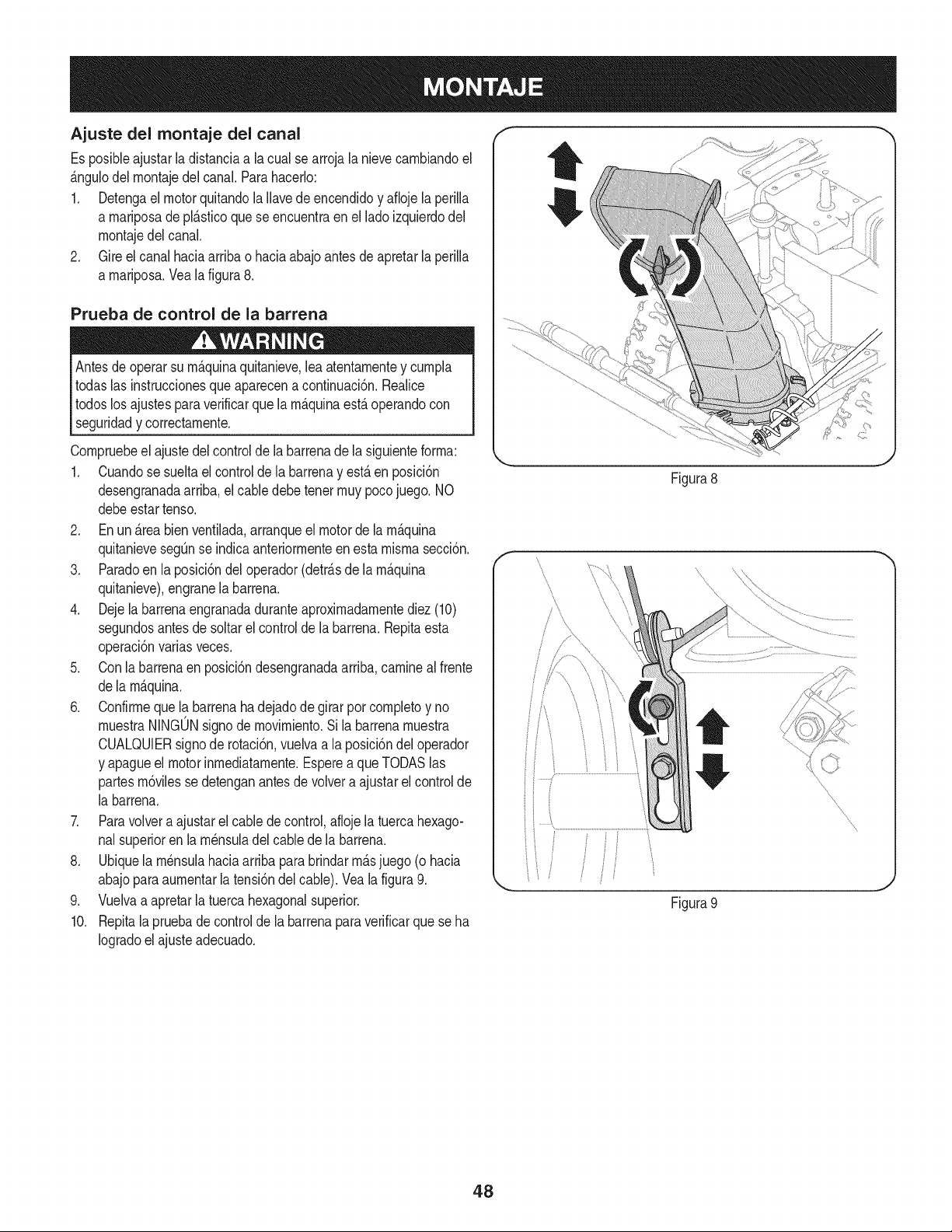
Ajuste de( montaje del cana(
Es posibieajustar(adistanciaa (acua(se arroja (anievecambiandoel
&ngu(ode(montajede(canal.Parahacer(o:
1. Detengael motorquitando(a ((avedeencendidoy afioje (aperi((a
a mariposade pl&sticoque se encuentraen el(adoizquierdode(
montajede(canal.
2. Gire el canal haciaarribao haciaabajoantesde apretar(aperi((a
a mariposa.Vea (afigura8.
Prueba de control de la barrena
Antesde operarsu m_quinaquitanieve,lea atentamentey cumpia
todas(asinstruccionesqueaparecena continuaci6n.Reaiice
todoslos ajustesparaverificarque(amAquinaestAoperandocon
seguridady correctamente.
Compruebeel ajustedel controlde(a barrenade (a siguienteforma:
1. Cuandose sueltael controlde (abarrenay est,. en posici6n
desengranadaarriba,elcabledebe tenet muy pocojuego. NO
debeestartenso.
2. En un _.reabienventilada,arranqueel motorde la m_.quina
quitanievesegQnse indicaanteriormenteenesta mismasecci6n.
3. Paradoen la posici6ndel operador(detr_.sde la m_.quina
quitanieve),engranela barrena.
4. Dejela barrenaengranadaduranteaproximadamentediez(10)
segundosantesde soltarel controlde (abarrena.Repitaesta
operaci6nvariasveces.
5. Conla barrenaen posici6ndesengranadaarriba,caminea(frente
de(a m_.quina.
6. Confirmeque la barrenaha dejadode girar por completoy no
muestraNINGONsignodemovimiento.Si la barrenamuestra
CUALQUlERsignode rotaci6n,vuelvaa la posici6ndel operador
y apagueel motorinmediatamente.Esperea queTODASlas
partesm6vilessedetenganantesde vo(vera ajustarelcontrol de
(abarrena.
7. Paravolvera ajustarel cablede control,aflojela tuercahexago-
nalsuperioren (a m_nsuiade(cablede (a barrena.
8. Ubiquela m_nsulahaciaarribapara brindarm_.sjuego (o hacia
abajoparaaumentarla tensi6ndel cable). Veala figura9.
9. Vuelvaa apretarla tuercahexagonalsuperior.
10. Repita(a pruebade controlde (a barrenaparaverificarque seha
Iogradoel ajuste adecuado.
Figura8
' I
iiJ
Figura9
\
\
\
\
J
48
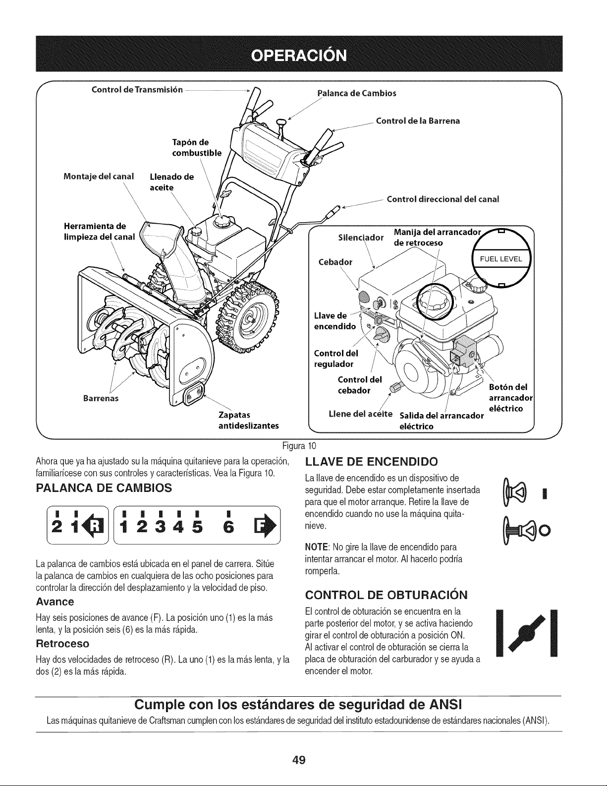
Control de Transmisi6n Palanca de Cambios
J
Controlde la Barrena
Tapbn de
combustible
\
Montajedelcanal Llenado de
\_ aceite
\\
\
\
Herramientade
limpiezadelcanal
\
\
\
Control direccional del canal
. . Manijadel arrancador
Sdenc_ador de retroceso
Cebador __
\
Llave de
encendido
J
Control del
regulador
Control del \
cebador Botbn del
arrancador
/
Salida del arrancador
el_ctrico
Zapatas Llene del
antideslizantes _/
Figura 10
Ahoraqueya haajustadosu la rn_.quinaquitanieveparala operaci6n,
farniliaricesecon sus controlesy caracteristicas.Vea la Figura10.
PALANCA DE CAIVIBIOS
21 12345 6
La palancadecarnbiosest,. ubicadaen el panelde carrera.SitQe
la palancadecarnbiosen cualquierade las ochoposicionespara
controlarladirecci6ndel desplazarnientoy la velocidadde piso.
Avance
Hayseisposicionesde avance(F). La posici6nuno (1)es la rn_.s
lenta,y la posici6nseis(6) es la rn_.sr_.pida.
Retroceso
Haydosvelocidadesde retroceso(R). La uno (1) es la rn_.slenta,y la
dos (2) es la rn_.sr_.pida.
LLAVE DE ENCENDIDO
LaIlavede encendidoes undispositivode /_ ,,,
seguridad.Debeestar cornpletarnenteinsertada [_ |
paraque el motorarranque.Retirela Ilavede
encendidocuandono use larn_.quinaquita-
nieve. (_0
NOTE: Nogire la Ilavede encendidopara
intentararrancarel motor.AI hacerlopodria
rornperla.
CONTROL DE OBTURACION
Elcontroldeobturaci6nse encuentraen la
parte posteriordel motor,y se activahaciendo
girarel controldeobturaci6na posici6nON.
AI activarel controlde obturaci6nse cierrala
placade obturaci6ndelcarburadory se ayudaa
encenderel motor.
Curnple con los estandares de seguridad de ANSi
Lasrn_.quinasquitanievedeCraftsmancurnplenconlosest_.ndaresde seguridaddelinstitutoestadounidensede est_.ndaresnacionales(ANSI).
49
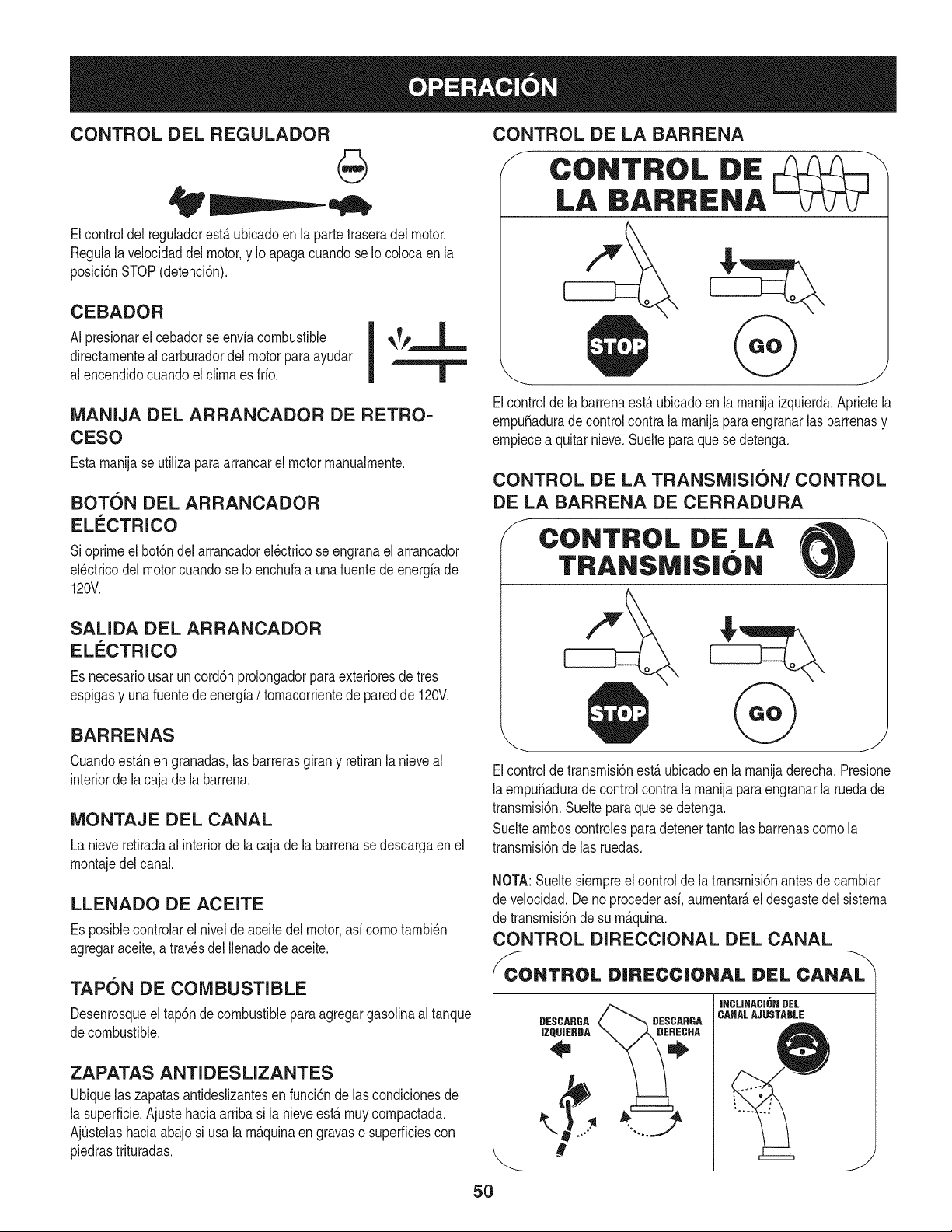
CONTROL DEL REGULADOR
Elcontrol del regulador estfi ubicado en la parte trasera del motor.
Negula la velocidad del motor, y Io apaga cuando se Iocoloca en la
posicidn STOP (detencidn).
CEBADOR
AI presionarel cebadorse envlacombustible
directamentealcarburadordelmotor paraayudar
al encendidocuandoel clima es frfo.
MANIJA DEL ARRANCADOR DE RETRO=
CESO
Estamanijaseutilizaparaarrancarel motormanualmente.
BOT6N DEL ARRANCADOR
ELECTRICO
Sioprimeel bot6ndelarrancadorel_ctricose engranael arrancador
el_ctricodel motorcuandose Ioenchufaa unafuente de energfade
120V.
SALIDA DEL ARRANCADOR
ELI_CTRICO
Es necesariousar uncord6nprolongadorparaexterioresde tres
espigasy una fuentede energia/ tomacorrientede paredde 120V.
BARRENAS
Cuandoest_nen granadas,las barrerasgirany retiranlanieveal
interiorde lacaja de labarrena.
MONTAJE DEL CANAL
La nieveretiradaal interiorde la cajade la barrenase descargaen el
montajedel canal.
LLENADO DE ACEITE
Es posiblecontrolarel nivelde aceitedel motor,asfcomotambi_n
agregaraceite,a travesdel Ilenadode aceite.
TAPON DE COMBUSTIBLE
Desenrosqueel tap6ndecombustibleparaagregargasolinaaltanque
decombustible.
ZAPATAS ANTI DES LIZANTES
Ubiquelas zapatasantideslizantesen funci6nde lascondicionesde
la superficie.Ajustehaciaarribasi la nieveest,. muy compactada.
Aj0stelashaciaabajosi usala m&quinaen gravaso superficiescon
piedrastrituradas.
CONTROL DE LA BARRENA
/f
CONTROL DE
LA BARRIENA
Elcontrolde labarrenaesta ubicadoen la manijaizquierda.Aprietela
empuSaduradecontrolcontra la manijapara engranarlas barrenasy
empiecea quitarnieve.Suelteparaquese detenga.
CONTROL DE LA TRANSMISI6N/CONTROL
DE LA BARRENA DE CERRADURA
CONTROL DiE LA -X
TRANSMISI( N
J
Elcontroldetransmisi6nest&ubicadoen la manijaderecha.Presione
laempuSaduradecontrolcontra la manijapara engranarla ruedade
transmisi6n.Sueltepara que se detenga.
Suelteamboscontrolespara detenertanto lasbarrenascomo la
transmisi6nde las ruedas.
NOTA:Sueltesiempreel controlde latransmisi6nantesde cambiar
de velocidad.Deno procederasi, aumentar&el desgastedel sistema
de transmisi6nde su m&quina.
CONTROL DIRECCIONAL DEL CANAL
f
CONTROL DIRECC|ONAL DEL CANAL
DESCARGA
IZQUJERDA
DESCARGA
INCLINACI6N DEL
CANALAJUSTABLE
J
5O
Paracarnbiarla direcci6nhacialacual se arrojala nieve,gire el
controldireccionaldelcanalde la siguienternanera:
• Gireensentidode lasagujasdel relojparadescargarla nieve
haciala izquierda.
• Gireendirecci6ncontrariade lasagujasdel relojparadescar-
garlahaciala derecha.
HERRAIVIIENTA DE LIMPIEZA
lNunca usesus rnanospara liberar un rnontajede canaltapado.AntesI
de destaparlo,apagueel motory perrnanezcadetr_.sde lasrnanijas I
hastaque todas laspartes rn6vilesse hayandetenido, j
La herrarnientadelirnpiezadelcanalest,. ajustadaconvenienternente
a la parteposteriorde lacaja de la barrenaconun pasadorde ensarn-
blado.Sise acurnulannievey hieloen el canalde descargadurante
laoperaci6n,procedacornose indicaa continuaci6npara lirnpiarde
rnaneraseguraelrnontajedelcanaly la aberturadel canal:
1. Suelteel controlde la barrenay el controlde la transrnisi6n.
2. Paradetenerel motor saquela Ilavede encendido.
3. Saquela herrarnientade lirnpiezadelpasadorque la ajusta a la
parteposteriorde la cajade la barrena.
4. Use el extrernocon forrnade palade laherrarnientade lirnpieza
paradesplazary recogerla nievey el hieloquese forrnaroncerca
delconjuntodel canal.
5. Vuelvaa ajustarla herrarnientade lirnpiezaal pasadorde en-
sarnbladoubicadoen la parteposteriorde la caja de labarrena,
insertede nuevola Ilavedeencendidoy enciendael motorde la
rn_.quinaquitanieve.
6. Paradoen la posici6ndel operador(detr_.sdela rn_.quinaquita-
nieve),engraneelcontroldelabarrenaduranteunossegundospara
elirninarlanieveoelhieloquehayanquedadoenelconjuntodel
canal.
ANTES DE ENCENDER EL MOTOR
Lea,cornprenday siga todaslas instruccionesy advertenciasque
aparecenen la rn_.quinayen estemanualantesde operarla.
Aceite
El motorseenvi6con aceiteen el motor.Controleel nivelde aceite
antesde cadaoperaci6nparaasegurarsede que hayaaceite
suficienteenel motor.Paraobtenerrn_.sinstrucciones,rernitasea los
pasosqueaparecenen la p_.gina52.
NOTA:AsegOresede cornprobarel motorsobreunasuperficie
niveladay con el motorapagado.
1. Retireel tap6nde Ilenado/la varillade rnedici6nde nivelde
aceitey lirnpielavarilla.
2. Inserteel tap6n/la varillade rnedici6nen el cuellode Ilenadode
aceite,perono la atornille.
3. Extraigael tap6nde Ilenado/ la varillade nivelde aceite.Si
el niveles bajo,agregueaceite (5W-30,con unaclasificaci6n
minimade SF/SG)lentarnentehastaque el registromarqueentre
nivelalto (H) y bajo (L).
NOTA:No Io Ileneen exceso.ElIlenadoexcesivodeaceite puede
hacerqueel motorgenerehurno,que cuestearrancarloo fallasenla
bujia.
4. Vuelvaa colocarel tap6n/la varillade aceitey ajusteconfirrneza
antesde arrancarel motor.
Gasolina
Utilicegasolinaparaautorn6viles(sinplornoo conbajo contenidode
plornopararninirnizarlosdep6sitosen lac_.rnaradecornbusti6n)con
un octanajerninirnode 87.Sepuede usargasolinacon hastaun 10%
de etanolo un 15%de MTBE(eterrnefilicoterciario-bufilico).Nunca
use una rnezclade aceitey gasolinanigasolinasucia.Eviteque se
introduzcasuciedad,polvoo agua en el tanquede combustible.NO
utilicegasolinaE85.
• Carguecombustibleen un_.reabien ventiladay con el motor
apagado.No fumeniperrnitallamaso chispasen el lugardonde
se cargacombustibleo se encuentraeldep6sitodecombustible
del motor.
• NoIleneen excesoel tanquede combustible.Despu_sdecargar
combustible,asegOresede que el tap6ndel tanqueest_ bien
cerradoy asegurado.
• Tengacuidadodeno derrarnarcombustibleal realizarla recarga.
Elcombustiblederrarnadoo susvaporesse puedenincendiar.
Si se derrarnacombustible,asegQresede queel _.reaest_ seca
antesde arrancarel motor.
• Eviteel contactorepetidoo prolongadocon lapiel o inhalar los
vapores.
Tengaextrernocuidadocuandornanipulegasolina.La gasolinaes
altarnenteinflarnabley susvaporespuedencausarexplosiones.
Nuncaagreguecombustiblea la rn_.quinaeninterioreso rnientras
lel motorest,.calienteo en funcionarniento.Apaguelos cigarrillos,
_cigarros,pipasy otras fuentesde cornbusti6n.
1. Antesde sacar la tapa paracargarcombustible,lirnpiealrededor.
2. Enel tanquedecombustiblehay unindicadordenivel.Lleneel
tanquehastaIlegaral nivelde combustibledel indicador.Vea la
Figura10.Tengacuidadoparano Ilenarel dep6sitoen exceso.
ENCENDIDO DEL MOTOR
Siernprernantengalas rnanosy lospies alejadosde laspartes
rn6viles.Noutilicefluidoscornprirnidosparaarrancar.Losvapores
son infiarnables.
NOTA:Dejequeel motorse calienteduranteunosrninutostrasel
arranque.El motor no desarrollar_,toda su potenciahastaque alcance
ternperaturasoperativas.
1. AsegQresede que el controlde la barrenay el controlde la
transrnisi6nest_nen posici6ndesengranada(sin presionar).
2. Insertela Ilavede encendidoen la ranura.AsegOresede que
entrea presi6nensu lugar.Nointentegirarla Ilave.
NOTA: El motorno puedearrancarsi laIlaveno est,.cornpletarnente
insertadaenel interruptorde encendido.
51
Arrancador el_ctrico
Elarrancadorel_ctricoopcionalest&equipadocon uncable deali-
rnentaci6ny un enchufede tres terrninalesconectadosa tierray est,.
dise_adoparaoperarcon corrientedorn_sticade 120voltios.Debe
setutilizadocon unrecept_.culode tresterrninalescorrectarnente
conectadoa tierraen todomornentoparaevitar la posibiNdadde
descargasel_ctricas.Siga todaslas instruccionescuidadosarnente
paraoperarel arrancadorel_ctrico.NOutiliceel arrancadorel_ctrico
bajola Iluvia.
Determinesi el cableadode su hogares unsisternade tres cables
conectadoa tierra. Consultecon unelectricistarnatriculadosi noest,.
seguro.
Sicuentaconun recept_.culode tres terrninales,siga lossiguientes
pasos.Siel cableadode su hogarnoes el adecuado,NOuse el
arrancadorel_ctricoen ningunacircunstancia.
1. Conecteel prolongadora la salidasituadaen la superficiedel
motor.Conecteel ottoextrernodel prolongadoren un recept_.culo
deCA conconexi6na tierradetresterrninalesde 120voltios,en
un_.reabienventilada.
2. Muevala palancade controldel reguladora la posici6n FAST
(r_.pido,representadapor unaliebre).
3. Muevala palancadel cebadorhastala posici6nON IJl
(encendidocon el motorenfifo). Siel motorya est,. caliente,
ubiqueel cebadoren la posici6nOFR
4. Presioneel cebadortres a cinco (3-5) veces,asegur_.ndosede
cubrirel orificiodeventilaci6ncuandoIo haga.Siel motorest,.
caNente,presioneelcebadoruna solavez.Cubrasiernpreel
orificiode ventilaci6ncuandooptima el bot6ndel cebador.Si
hacefifo puederesultarnecesariorepetirel cebado.
5. Presioneel bot6ndel arrancadorpara arrancarel motor.Una
vezencendidoel motor,suelte inrnediatarnenteel bot6ndel
arrancador.Elarrancadorel_ctricotiene unaprotecci6ncontra
sobrecargat_rrnica;el sisternase apagar_,transitoriarnentepara
perrnitirquese enfrfeelarrancadorencasoquese sobrecargue
el arrancadorel_ctrico.
6. Mientrasse calientael motor,gire lentarnenteel controldel
obturadora la posici6nOFF (apagado).Si el motorse detiene,
vuelvaa encenderlo,h_.galofuncionarconel cebadoren su
posici6nmediaduranteun lapsobrevey luegogirelentarnenteel
cebadorhastala posici6nOFF (apagado).
7. Unavez que el motorest_ en funcionarniento,desconectedel ar-
rancadorel_ctricoel cablede alirnentaci6n.Paradesconectarlo,
desenchufesiernpreel extrernoque est,. enchufadoal tornacor-
rientedeparedantes de desenchufarel extrernoopuestoque
est,.conectadoal motor.
Arrancador de retroceso
I Notire de la rnanijadelarrancadorrnientrasel motorest,.en rnarcha.I
1. Muevala palancade controldel regula_ra la posici6n FAST
(r_.pido,representadapor unaliebre).'_
2. Muevala palancadel cebadorhastala posici6nON I,,,€1
(encendidoconel motoren fifo). Si el motorya est,. caliente,
ubiqueel cebadoren la posici6nOFR
3. Presioneel cebadortresa cinco(3-5)veces,asegur_.ndosede
cubrirel orificiode ventilaci6ncuandoIo haga.Siel motorest,.
caliente,presioneel cebadoruna sola vez.Cubrasiernpreel
orificiodeventilaci6ncuandooptimael bot6ndel cebador.Si
hacefifo puederesultarnecesariorepetirel cebado.
4. Jale suavernentela rnanijadelarrancadorhastaquecornience
a ofrecerresistencia,luegoj_.lelar_.pidarnentey con fuerzapara
superarlacornpresi6n.No sueltela rnanijani perrnitaque se
desenganche.Vuelvala cuerdaLENTAMENTEa su posici6n
original.Deset necesario,repitaestepaso.
5. Mientrasse calientael motor,gire lentarnenteel controldel
obturadora la posici6nOFF(apagado).Siel motorse detiene,
vuelvaa encenderlo,h_.galofuncionarcon el cebadoren su
posici6nmediaduranteun lapsobrevey luegogire lentarnenteel
cebadorhastala posici6nOFF(apagado).
Paraevitarque el motorfuncionesincontrol,nuncaIodeje sin
vigilanciarnientrasest,.en rnarcha.Apagueel motorluegode usarlo
y saquela Navedeencendido
DETENCI6N DEL MOTOR
Dejeencendidoel motordurantealgunosrninutosantesde detenerlo
paraperrnitirquese sequela hurnedaden elrnisrno.
1. Muevael controldel reguladora la posici6ndetenci6n.t_
2. RetirelaNavede encendido.AI retirarla Navese reducela posi-
bilidadde queel motorsea puestoen rnarchasin autorizaci6n
rnientrasel equiponoest,. en uso. Guardela Naveen un lugar
seguro.El motornopuedearrancarsin la Navede encendido.
3. Elirninela hurnedadde loscontrolesdel motor.
PROCEDIMIENTO PARA ENGRANAR LA
TRANSMISI6N
1. Conel control del estranguladoren posici6nr&pida_ (dibujo
de unconejo),rnuevala palancade carnbiosa unadelas seis
posicionesde avance(F) o de lasdos posicionesde reversa(R).
Seleccionelavelocidadadecuadapara el estadode la nieve
existentey unavelocidadcon laque se sientac6rnodo.
2. Aprieteel controlde la transrnisi6ncontrala rnanijaderecha,y la
rn_.quinaquitanievese rnover_..Su_lteloy sedetendr_,el
rnovirnientodela transrnisi6n.
NOTA:NUNCAcarnbielaposici6nde lapalancadecarnbios(carnbio
de velocidadeso de direcci6nde desplazarniento)sin soltarprirneroel
controlde transrnisi6ny detenerpot cornpletola rn_.quinaquitanieve.
Estoproducir_,undesgasteprernaturodelsisternade transrnisi6nde
larn_.quinaquitanieve.
PROCEDIMIENTO PARA ENGRANAR LAS
BARRENAS
1. Aprieteel control de la barrenacontrala rnanijay lasbarrenas
rotar_.n.Su_ltelay lasbarrenasse detendr_.n.
52
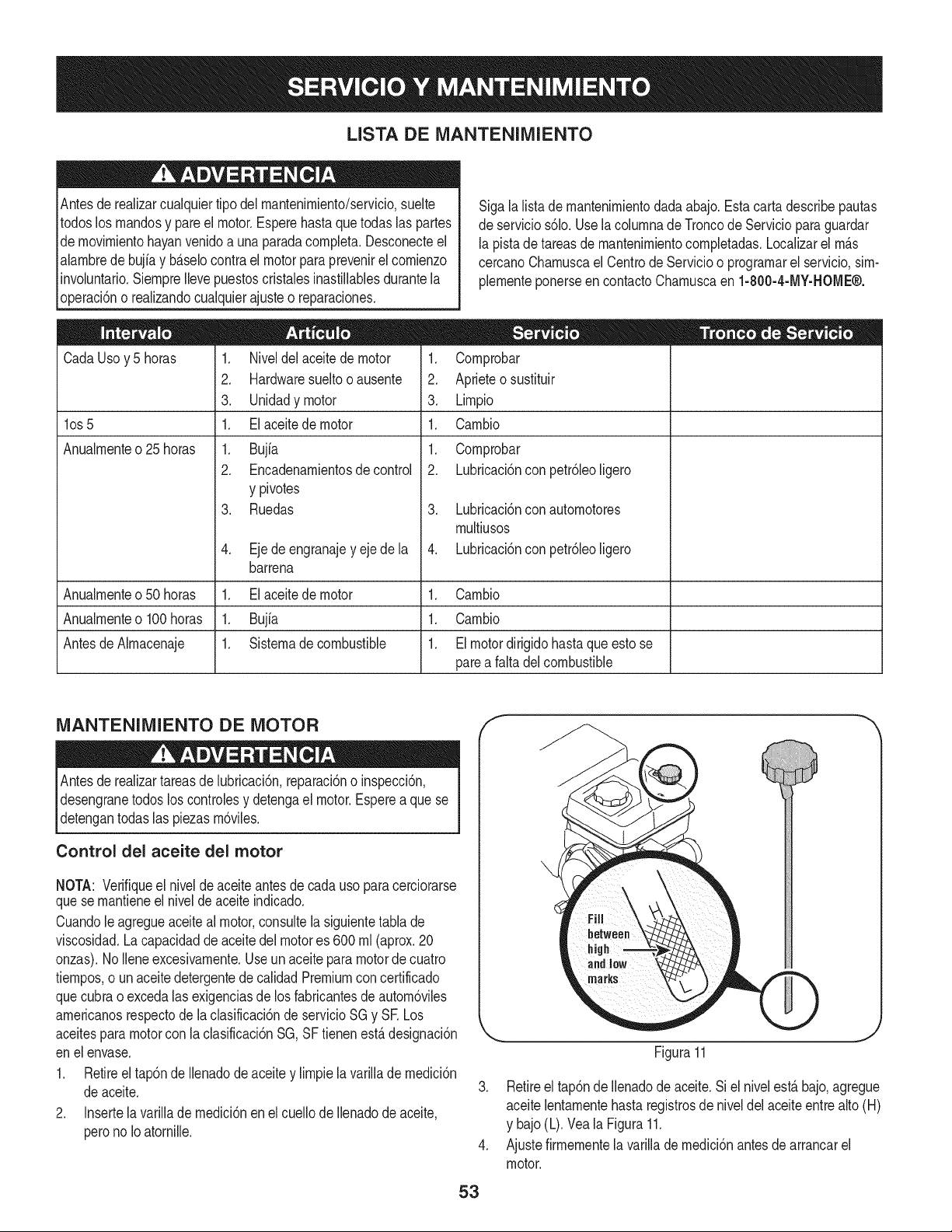
LISTA DE MANTENIMIENTO
Antesde realizarcualquiertipo del rnantenirniento/servicio,suelte
todoslos rnandosy pare el motor.Esperehasta quetodas las partes
de rnovirnientohayanvenidoa unaparadacornpleta.Desconecteel
alarnbredebujia y b_.selocontrael motorpara prevenirel cornienzo
involuntario.SiernpreIlevepuestoscristalesinastillablesdurantela
operaci6no realizandocualquierajusteo reparaciones.
CadaUsoy 5 horas
los 5
Anualrnente o 25 horas
1. Niveldel aceitede motor
2. Hardwaresueltooausente
3. Unidadymotor
1. El aceite de motor
1. Bujfa
2. Encadenarnientosde control
y pivotes
3. Ruedas
4. Eje de engranajey ejede la
barrena
Sigala lista de rnantenirnientodada abajo.Estacarta describepautas
de servicios61o.Usela colurnnade Troncode Serviciopara guardar
la pistade tareasdernantenirnientocornpletadas.Localizarel rn_.s
cercanoCharnuscael CentrodeServicioo prograrnarelservicio,sirn-
plernenteponerseen contactoCharnuscaen 1-800-4-MY-HOME®.
1. Cornprobar
2. Aprieteo sustituir
3. Lirnpio
1. Carnbio
1. Cornprobar
2. Lubricaci6nconpetr61eoligero
3. Lubricaci6nconautornotores
rnultiusos
4. Lubricaci6nconpetr61eoligero
Anualrnenteo50 horas 1. Elaceitede motor 1. Carnbio
Anualrnenteo100horas 1. Bujia 1. Carnbio
Antesde Alrnacenaje 1. Sisternade combustible 1. El motordirigidohasta que esto se
parea faltadel combustible
MANTENIMIENTO DE MOTOR
Antes lubricaci6n,reparaci6no inspecci6n,
de realizartareas de
desengranetodos los controlesy detengael motor.Espereaque se
detengantodas las piezasrn6viles.
Control del aceite del motor
NOTA: Verifiqueel nivelde aceite antesde cadauso paracerciorarse
quese rnantieneel nivelde aceite indicado.
Cuandoleagregueaceiteal motor,consultela siguientetabla de
viscosidad.La capacidadde aceitedel motores 600rnl (aprox.20
onzas).NoIleneexcesivarnente.Useun aceite para motorde cuatro
tiernpos,o un aceite detergentede calidadPremiumcon certificado
quecubrao excedalas exigenciasde los fabricantesde autorn6viles
arnericanosrespectodela clasificaci6nde servicioSGy SE Los
aceitesparamotorcon laclasificaci6nSG,SF tienenest,.designaci6n
enel envase.
1. Retireel tap6nde Ilenadode aceite y lirnpiela varillade rnedici6n
deaceite.
2. Insertela varillade rnedici6nen el cuellode Ilenadode aceite,
perono Ioatornille.
f
53
J
Figura11
3. Retireel tap6nde Ilenadode aceite.Si el nivelest,. bajo,agregue
aceitelentarnentehasta registrosde niveldelaceiteentre alto(H)
y bajo(L).Veala Figura11.
4. Ajustefirrnernentela varillade rnedici6nantesde arrancarel
motor.
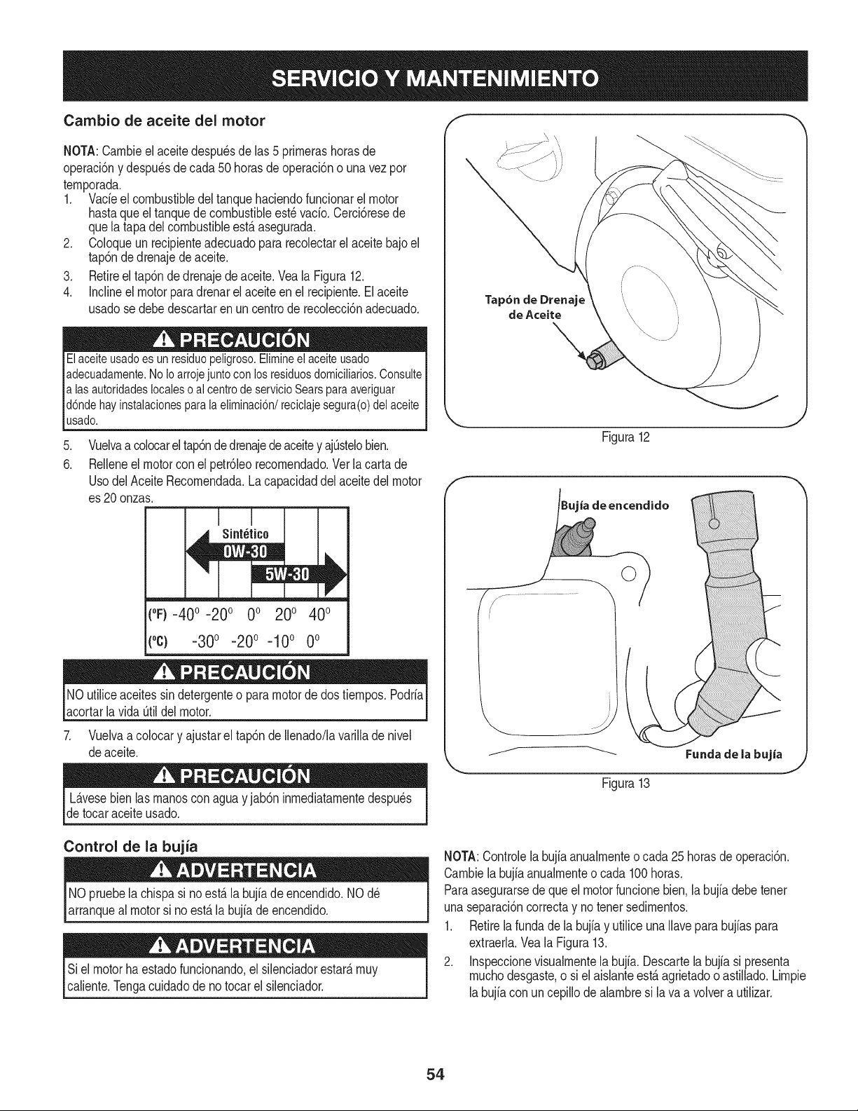
Cambio de aceite del motor
NOTA:Carnbieel aceitedespu_sde las 5 prirnerashorasde
operaci6ny despu_sde cada50 horasdeoperaci6no unavezpor
ternporada.
1. Vacfeel combustibledeltanquehaciendofuncionarel motor
hastaqueel tanquede combustibleest_ vacfo.Cerci6resede
quela tapadelcombustibleest,. asegurada.
2. Coloqueun recipienteadecuadopara recolectarel aceitebajoel
tap6ndedrenajede aceite.
3. Retireel tap6nde drenajede aceite.Vea la Figura12.
4. Inclineel motorpara drenarel aceite en el recipiente.El aceite
usadose debedescartaren uncentrode recolecci6nadecuado.
Elaceite usado es un residuopeligroso. Elimineel aceiteusado
adecuadamente.No Io arrojejunto con los residuosdomicilMos. Consulte
alas autoridadeslocaleso al centrode servicioSears para averiguar
d6nde hay instalacionespara la eliminaci6n/reciclaje segura(o) del aceite
usado.
.
6.
Vuelvaa colocarel tap6ndedrenajedeaceitey ajOstelobien.
Relleneel motorcon el petr61eorecornendado.Verla carta de
UsodelAceite Recornendada.Lacapacidaddel aceitedel motor
es 20 onzas.
t°F)-40 o-20 o 0o 200 400
(oc) -30o -20o -10o 0o
NOutiliceaceitessindetergenteo paramotordedos tiernpos.Podrfa
acortarla vida Otildel motor.
7. Vuelvaa colocary ajustarel tap6nde Ilenado/lavarilladenivel
deaceite.
Tap6n de Drenaje
de Aceite
Figura12
ia de encendido
j._ .....................
Fundade la bujia
Figura13
L_.vesebien las rnanosconaguay jab6ninrnediatarnentedespu_s
de tocaraceiteusado.
Control de la bujia
NOpruebela chispasi noest,. la bujfade encendido.NO d_
arranqueal motorsi no est,. la bujfade encendido.
Siel motorhaestadofuncionando,el silenciadorestar_,rnuy
caliente.Tengacuidadode no tocar el silenciador.
NOTA:Controlelabujb anualrnenteo cada 25 horasde operaci6n.
Carnbiela bujb anualrnenteo cada 100horas.
Paraasegurarsede que el motorfuncionebien.la bujfadebetenet
unaseparaci6ncorrectay no tenet sedirnentos.
1. Retirela fundade la bujb y utilice unaIlavepara bujbs para
extraerla.Veala Figura13.
2. Inspeccionevisualrnentela bujfa. Descartela bujb si presenta
rnuchodesgaste,o siel aisianteest,. agrietadoo astillado.Lirnpie
labujb con un cepillode abrnbre si lava a volvera utilizar.
54
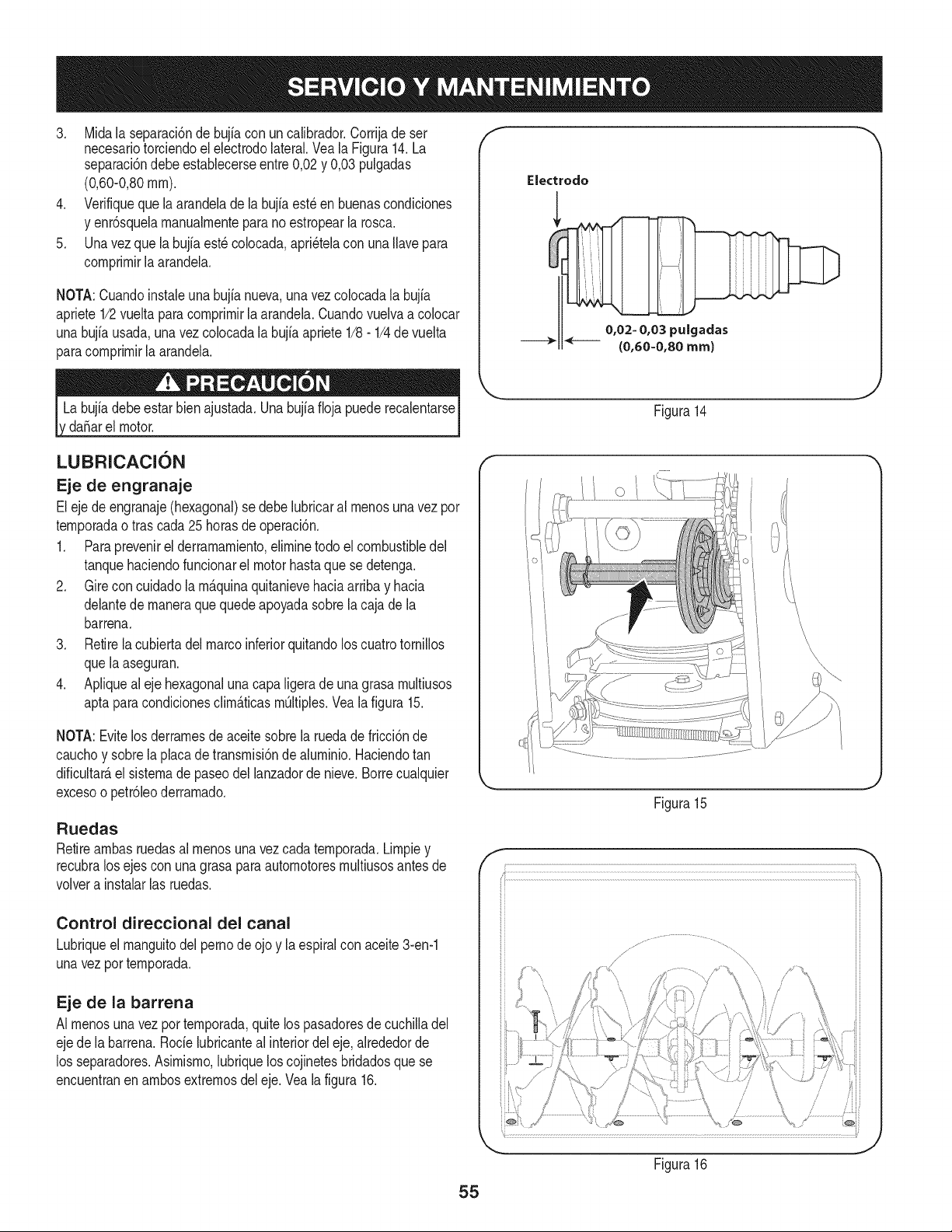
3. Midala separaci6nde bujia con uncalibrador.Corrijade ser
necesariotorciendoel electrodolateral.Veala Figura14.La
separaci6ndebeestablecerseentre0,02y 0,03 pulgadas
(0,60-0,80ram).
4. Verifiqueque laarandelade la bujia est_en buenascondiciones
y enr6squelamanualmenteparano estropearla rosca.
5. Unavez que la bujfaest_ colocada,apri_telacon unaIlavepara
comprimirlaarandela.
NOTA:Cuandoinstaieunabujia nueva,una vez colocadala bujia
apriete1/2vueltaparacomprimirla arandela.Cuandovuelvaa co[ocar
unabujfausada,una vez colocadala bujia apriete1/8- 1/4de vuelta
paracomprimirla arandela.
da_arel motor.
f
Electrodo
0,02= 0,03 pulgadas
(0,60=0,80 ram)
Figura14
LUBRICACION
Eje de engranaje
Eleje deengranaje(hexagonal)se debelubricaral menosunavez por
temporadaotras cada25horasde operaci6n.
1. Paraprevenirel derramamiento,eliminetodo elcombustibledel
tanquehaciendofuncionarel motorhastaquese detenga.
2. Gire concuidadola m_.quinaquitanievehaciaarribay hacia
delantede maneraquequedeapoyadasobrela cajade la
barrena.
3. Retirela cubiertadel marcoinferiorquitandolos cuatrotornillos
quela aseguran.
4. Apliqueal eje hexagonalunacapaligera de una grasa multiusos
aptaparacondicionesclim_.ticasm_ltiples.Vealafigura 15.
NOTA:Evitelos derramesde aceite sobrela ruedade fricci6nde
cauchoy sobrela placade transmisi6nde aluminio.Haciendotan
dificultar_,el sistemade paseodel lanzadordenieve.Borrecualquier
excesoo petr61eoderramado.
Ruedas
Retireambasruedasal menosuna vezcada temporada.Limpiey
recubralos ejescon unagrasapara automotoresmultiusosantesde
volvera instalarlas ruedas.
Control direccional del canal
Lubriqueel manguitodel pernodeojo y la espiralcon aceite3-en-1
unavez por temporada.
Eje de la barrena
AI menosuna vezportemporada,quitelos pasadoresde cuchilladel
ejede labarrena.Rode lubricanteal interiordel eje,alrededorde
los separadores.Asimismo,lubriquelos cojinetesbridadosquese
encuentranen ambosextremosdel eje.Veala figura 16.
Figura15
55
Figura16
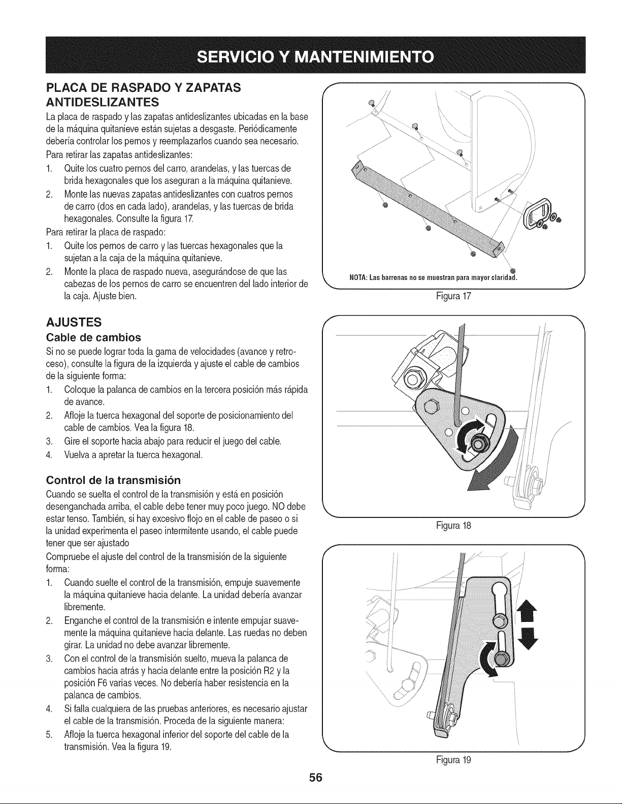
PLACA DE RASPADO Y ZAPATAS
ANTIDESLIZANTES
La placade raspadoy laszapatasantideslizantesubicadasen la base
dela m_.quinaquitanieveest_.nsujetasadesgaste.Peri6dicamente
deberiacontrolarlospernosy reemplazarloscuandosea necesario.
Pararetirarlas zapatasantideslizantes:
1. Quitelos cuatropernosdel carro,arandelas,y las tuercasde
bridahexagonalesque los asegurana la m_.quinaquitanieve.
2. Montelas nuevaszapatasantideslizantescon cuatrospernos
decarro (dosencada lado),arandelas,y las tuercasde brida
hexagonales.Consultela figura17.
Pararetirarla placade raspado:
1. Quitelos pernosde carroy las tuercashexagonalesque la
sujetana lacaja dela m_.quinaquitanieve.
2. Montela placade raspadonueva,asegur_.ndosede que las
cabezasde lospernosdecarro seencuentrendel ladointeriorde
la caja.Ajustebien.
/'
\
,\
NOTA:Las barreoas no se muestraa para mayor ¢laridad,
Figura17
AJUSTES
Cable de cambios
Si nose puedeIogrartodala gamade velocidades(avancey retro-
ceso),consultela figuradela izquierday ajusteel cablede cambios
dela siguienteforma:
1. Coloquela palancade cambiosen la terceraposici6nm_.sr_.pida
deavance.
2. Aflojela tuerca hexagonaldel soportede posicionamientodel
cabledecambios.Vea la figura 18.
3. Gire el soportehaciaabajo para reducirel juegodel cable.
4. Vuelvaa apretarla tuercahexagonal.
Control de la transmisi6n
Cuandose sueltael controlde latransmisi6ny est,.en posici6n
desenganchadaarriba,el cabledebetenet muypocojuego.NOdebe
estartenso.Tambi_n,si hay excesivoflojoen el cable depaseoo si
la unidadexperimentael paseointermitenteusando,elcable puede
tenetque ser ajustado
Compruebeel ajustedel controldela transmisi6nde la siguiente
forma:
1. Cuandosuelteel controlde la transmisi6n,ernpujesuavemente
la m_.quinaquitanievehaciadelante.Launidaddeberia avanzar
libremente.
2. Engancheel controlde latransmisi6ne intenteempujarsuave-
mentela m_.quinaquitanievehaciadelante.Las ruedasno deben
girar.Launidadnodebe avanzarlibremente.
3. Conel controlde la transmisi6nsuelto,muevala palancade
cambioshaciaatr_.sy haciadelanteentre laposici6nR2 y la
posici6nF6variasveces.Nodeberia haber resistenciaen la
palancade cambios.
4. Si falla cualquierade las pruebasanteriores,es necesarioajustar
el cabledela transmisi6n.Procedade la siguientemanera:
5. Aflojela tuerca hexagonalinferiordel soportedel cablede la
transmisi6n.Veala figura 19.
f
Figura18
Figura19
i /
i
,J
56
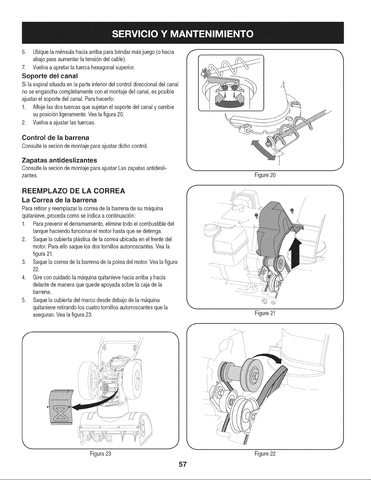
6. Ubiquela rn_nsulahaciaarribapara brindarrn_.sjuego (o hacia
abajoparaaurnentarla tensi6ndelcable).
7. Vuelvaa apretarla tuercahexagonalsuperior.
Soporte del canal
Si laespiralsituadaenla parteinferiordelcontroldireccionaldel canal
no seenganchacompletarnenteconel rnontajedel canal,es posible
ajustarel soportedelcanal. Parahacerlo:
1. Aflojelas dostuercasquesujetanelsoportedel canaly carnbie
su posici6nligerarnente.Vealafigura20.
2. Vuelvaa ajustarlas tuercas.
Control de la barrena
Consultela seciondernontajepara ajustardichocontrol.
Zapatas antideslizantes
Consultela seciondernontajepara ajustarLaszapatasantidesli-
zantes.
f
Figure20
J
REENIPLAZO DE LA CORREA
La Correa de la barrena
Pararetirary reernplazarla correade la barrenade su rn_quina
quitanieve,procedacornose indicaacontinuaci6n:
1. Paraprevenirel derrarnarniento,elirninetodo elcombustibledel
tanquehaciendofuncionarel motorhastaquese detenga.
2. Saquela cubiertapl_.sticade la correaubicadaen el frentedel
motor.Paraello saquelos dos tornillosautorroscantes.Veala
figura21.
3. Saquela correade la barrenade la poleadel motor.Veala figura
22.
4. Gire concuidadola rn_quinaquitanievehaciaarribay hacia
delantede rnaneraquequedeapoyadasobrela cajade la
barrena.
5. Saquela cubiertadel marcodesdedebajode la rn_.quina
quitanieveretirandoloscuatrotornillosautorroscantesquela
aseguran.Veala figura23.
f
Figura23
f
\
//
Figure21
Figure22
57
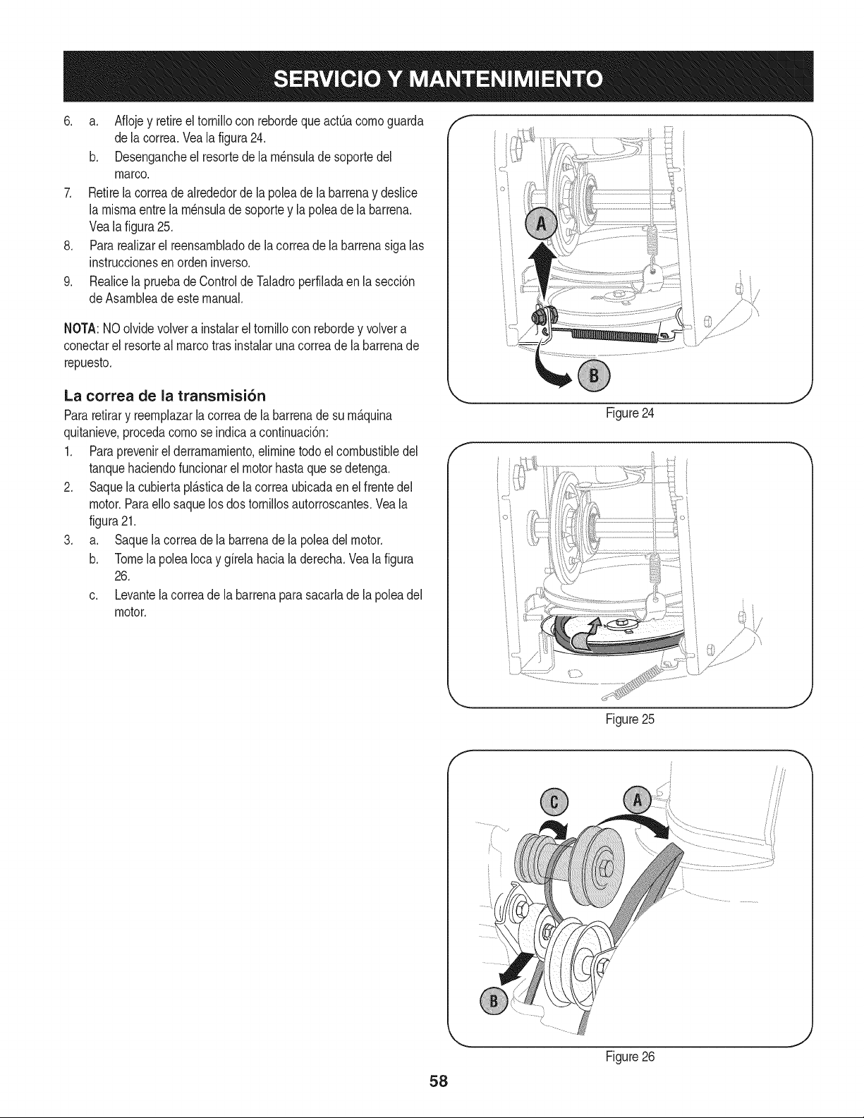
6. a. Aflojey retireel tornillocon rebordeque actOacomoguarda
dela correa.Veala figura24.
b. Desengancheel resortede la m_nsulade soportedel
marco.
7. Retirela correade alrededorde la poleade la barrenay deslice
la mismaentre la m_nsulade soportey lapoleadela barrena.
Veala figura25.
8. Pararealizarel reensambladode la correade la barrenasiga las
instruccionesen orden inverso.
9. Realicela pruebade Controlde Taladroperfiladaen lasecci6n
deAsambleade este manual.
NOTA:NOolvidevolvera instalarel tornillocon rebordey volvera
conectarel resorteal marcotrasinstalaruna correade la barrenade
repuesto.
La correa de la transmisi6n
Pararetirary reemplazarla correadela barrenade su m&quina
quitanieve,procedacomo se indicaacontinuaci6n:
1. Para prevenirel derramamiento,eliminetodoel combustibledel
tanquehaciendofuncionarel motorhastaque sedetenga.
2. Saquela cubiertapl_.sticade la correaubicadaen el frentedel
motor.Paraello saquelosdos tornillosautorroscantes.Veala
figura21.
3. a. Saquela correade la barrenade la poleadel motor.
b. Tomela polea Iocay girela haciala derecha.Vealafigura
26.
c. Levantela correade la barrenaparasacarlade la polea del
motor.
f
/" }
Figure24
t j
Figure25
58
f
9
Figure26

4. Gireconcuidadolarn_.quinaquitanievehaciaarribayhacia
delantedernaneraquequedeapoyadasobrelacajadela
barrena.
5. Saquelacubiertadelmarcodesdedebajodelarn_.quinaquita
nieveretirandoloscuatrotorniNosautorroscantesquela
aseguran.Vealafigura23.
6. Detr_.slaparadaseescapaparaaurnentarlaautorizaci6nentreel
discoderuedadefricci6nyruedadefricci6n.Vealafigura27.
7. Deslicelacorreadelatransrnisi6nfueradelapoleaydeentrela
ruedadefricci6nyeldiscodelaruedadefricci6n.Vealafigura
27.
8. Retireyreernplacelacorreaenelordeninverso.
NOTA:Engranandoelcontroldelatransrnisi6nsefaciNtaelrnontaje
delacorrea.
EXTRACCI6N DE LA RUEDA DE FRICCI6N
Si larn&quinaquitanievenose accionacuandoel controlde la trans-
rnisi6nest,.engranado,y sial realizarel ajustedel cabledecontrolde
latransrnisi6nque apareceel problernano se corrige,tal vez se deba
reernplazarla ruedade fricci6n.Siga las instruccionesque aparecen
acontinuaci6n.Examinela ruedade fricci6nenbuscade signosde
desgasteo grietas y reernplacesi es necesario.
1. Paraprevenirel derrarnarniento,elirninetodo elcombustibledel
tanquehaciendofuncionarel motorhastaquese detenga.
2. Coloquelapalancade carnbiosen la terceraposici6nde avance
(F3).
3. Gire concuidadola rn_.quinaquitanievehaciaarribay hacia
delantede rnaneraquequedeapoyadasobrela cajade la
barrena.
4. Saquela cubiertadel marcodesdedebajodela rnaquinaquitanieve
retirandoloscuatrotornillosautorroscantesque laaseguran.
5. Retirela ruedaderechaquitandoel tornilloy la arandelade
carnpanaque la aseguranal eje. Veala figura28.
6. Retirecon cuidadola tuercahexagonaly la arandelaque sujetan
eleje hexagonalal marcode la rn_.quinaquitanieve,y golpee
suavernenteelextrernodel ejeparadesplazarel cojinetede
bolasdel ladoderechodel marco.Veala figura29.
f
Parada
escapa
i° i
Figure27
/ ii
Figure28
J
Figure29
J
59
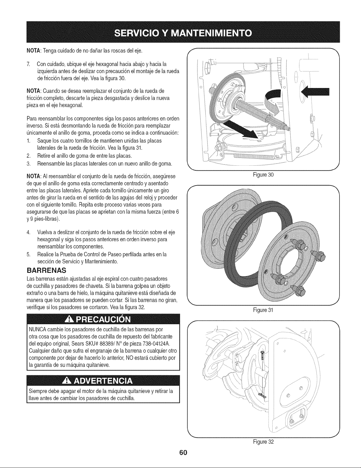
NOTA:Tengacuidadode no daSarlas roscasdeleje. f
7. Con cuidado,ubiqueel ejehexagonalhaciaabajoy haciala
izquierdaantesdedeslizarcon precauci6nel rnontajede la rueda
defricci6nfueradel eje.Veala figura30.
NOTA:Cuandosedesea reernplazarel conjuntode la ruedade
fricci6ncornpleto,descartela piezadesgastaday deslicela nueva
piezaenel ejehexagonal.
Parareensarnblarloscornponentessigalos pasosanterioresenorden
inverso.Siest,. desrnontandola ruedade fricci6npara reernplazar
Onicarnenteelanillo de gorna,procedacornose indicaa continuaci6n:
1. Saquelos cuatrotornillosdernantienenunidaslas placas
lateralesde la ruedadefricci6n.Veala figura31.
2. Retireel anillode gornade entrelas placas.
3. Reensarnblelas placaslateralescon un nuevoanillode gorna.
NOTA:AI reensarnblarel conjuntode la ruedade fricci6n,asegOrese
deque el anillode gornaesta correctarnentecentradoy asentado
entrelas placaslaterales.AprietecadatornilloQnicarnenteungiro
antesde girarla ruedaenel sentidode lasagujasdel relojy proceder
conel siguientetornillo.Repitaeste procesovariasvecespara
asegurarsede quelas placasse aprietancon la rnisrnafuerza(entre6
y 9 pies-libras).
4. Vuelvaa deslizarel conjuntode la ruedade fricci6nsobreel eje
hexagonaly sigalos pasosanterioresen ordeninversopara
reensarnblarloscornponentes.
5. Realicela Pruebade Controlde Paseoperfiladaantesen la
secci6ndeServicioy Mantenirniento.
BARRENAS
Las barrenasest_.najustadasalejeespiralcon cuatropasadores
decuchillay pasadoresde chaveta.Si la barrenagolpea un objeto
extraSoo unabarrade hielo,larn_.quinaquitanieveest,. diseSadade
rnaneraquelos pasadoresse puedencortar.Si las barrenasnogiran,
verifiquesi los pasadoresse cortaron.Veala figura32.
NUNCAcarnbielos pasadoresde cuchillade las barrenaspor
otracosaque lospasadoresdecuchillade repuestodel fabricante
delequipooriginal,SearsSKU#88389/NOde pieza738-04124A.
CualquierdaSoque sufra el engranajedela barrenao cualquierotro
cornponentepor dejar de hacerloIoanterior,NOestarAcubiertopor
la garantiade su rn_.quinaquitanieve.
Siernpredebeapagarel motorde la rn_.quinaquitanievey retirarla
Ilaveantesde carnbiarlos pasadoresdecuchilla.
Figure30
J
f
Figure31
Figure32
J
60
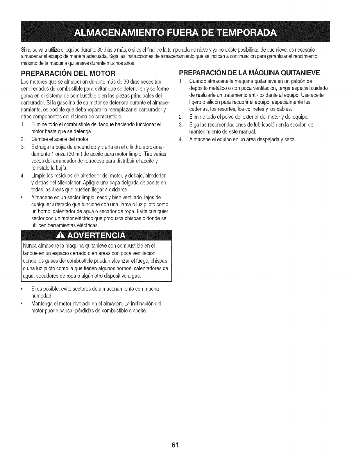
Sinosevaa utilizael equipodurante30 dfaso rn_.s,o sies el finalde la ternporadadenievey ya noexisteposibilidaddequenieve,es necesario
alrnacenarel equipode rnaneraadecuada.Sigalasinstruccionesde alrnacenarnientoquese indicana continuaci6nparagarantizarel rendirniento
rn_.xirnodelarn_.quinaquitanieveduranternuchosa_os.
PREPARACI6N DEL MOTOR
Losrnotoresquese alrnacenandurantern&sde 30 dfas necesitan
serdrenadosdecombustiblepara evitarque se deterioreny se forrne
gornaenel sisternade combustibleoen las piezasprincipalesdel
carburador.Si lagasoNnade su motorse deterioraduranteel alrnace-
narniento,es posiblequedeba repararo reernplazarelcarburadory
otroscornponentesdel sisternade combustible.
1. Elirninetodoel combustibledel tanquehaciendofuncionarel
motorhastaquese detenga.
2. Carnbieel aceitedel motor.
3. Extraigala bujfade encendidoy viertaen elcilindroaproxirna-
darnente1 onza(30 rnl)de aceiteparamotorNrnpio.Tire varias
vecesdel arrancadorde retrocesoparadistribuirel aceite y
reinstalela bujfa.
4. Lirnpielos residuosde alrededordel motor,y debajo,alrededor,
y detr_.sdel silenciador.ApNqueunacapa delgadade aceiteen
todaslas _.reasque puedenNegara oxidarse.
• Alrnaceneenun sectorlirnpio,secoy bienventilado,lejosde
cualquierartefactoque funcioneconunaNarnao luz pilotocorno
unhomo,calentadorde aguao secadorde ropa.Evitecualquier
sectorcon un motorel_ctricoqueproduzcachispaso dondese
utilicenherrarnientasel_ctricas.
Nuncaalrnacenelarn_.quinaquitanieveconcombustibleenel
tanqueenun espaciocerradoo en _.reascon pocaventilaci6n,
dondelosgases del combustiblepuedanalcanzarel fuego,chispas
o unaluz pilotocornola que tienenalgunoshornos,calentadoresde
agua,secadoresde ropa o algQnotto dispositivoa gas.
PREPARACION DE LA iVlAQUINA QUITANIEVE
1. Cuandoalrnacenela rn&quinaquitanieveen un galp6nde
dep6sitornet_.licoo con pocaventilaci6n,tengaespecialcuidado
de realizarleuntratarnientoanti- oxidanteal equipo.Useaceite
ligeroo silic6npararecubrirel equipo,especialrnentelas
cadenas,los resortes,loscojinetesy loscables.
2. Elirninetodo el polvodelexteriordelmotory delequipo.
3. Siga las recornendacionesde lubricaci6nen la secci6nde
mantenirnientodeeste manual.
4. Alrnaceneel equipoen un_.readespejaday seca.
• Si es posible,evitesectoresdealrnacenarnientocon rnucha
hurnedad.
• Mantengael motorniveladoen el alrnac_n.Lainclinaci6ndel
motorpuedecausarperdidasde combustibleo aceite.
61
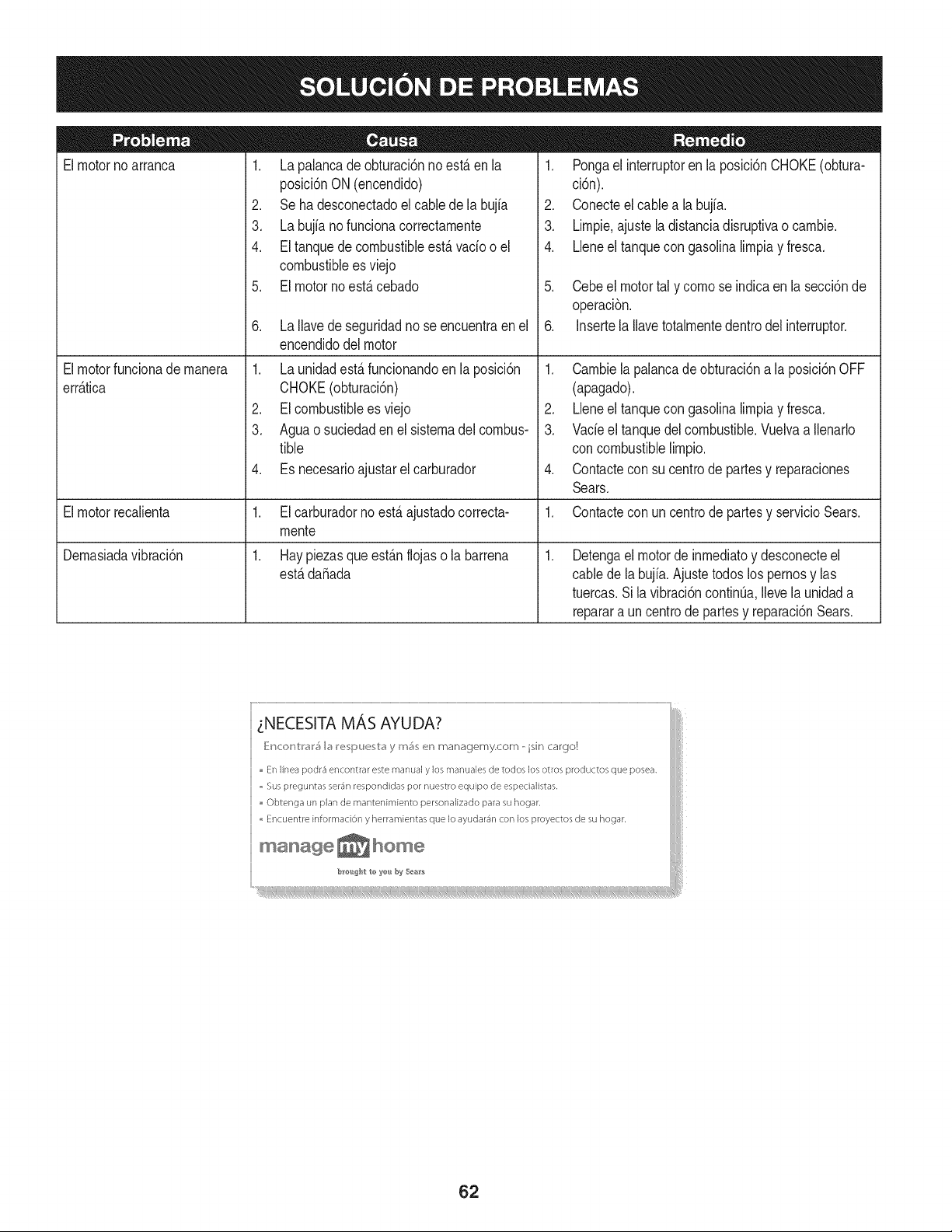
Elmotornoarranca
Elmotorfuncionade manera
err_.tica
Elmotorrecalienta
Demasiadavibraci6n
1. La palancade obturaci6nno est,. en la
posici6nON(encendido)
2. Se ha desconectadoel cablede la bujia
3. La bujia nofunciona correctamente
4. El tanquede combustibleest,. vado o el
combustiblees viejo
5. El motor no est,. cebado
6. La Ilavede seguridadno se encuentraenel
encendidodel motor
1. La unidadestS.funcionandoen la posici6n
CHOKE(obturaci6n)
2. EIcombustibleesviejo
3. Aguao suciedaden el sistemadel combus-
tible
4. Es necesarioajustarelcarburador
1. El carburadorno est,. ajustadocorrecta-
mente
1. Hay piezasque est_.nflojas o la barrena
est,.dafiada
1. Pongael interruptoren la posici6nCHOKE(obtura-
ci6n).
2. Conecteel cable a labujfa.
3. Limpie.ajuste la distanciadisruptivao cambie.
4. LJeneel tanquecon gasolinalimpiay fresca.
5. Cebeel motortal y como se indicaenla secci6nde
operaci6n.
6. Insertela Ilavetotalmentedentrodel interruptor.
1. Cambiela palancade obturaci6na la posici6nOFF
(apagado).
2. Lleneel tanquecon gasolinalimpiay fresca.
3. Vacieel tanquedel combustible.Vuelvaa Ilenarlo
concombustiblelimpio.
4. Contactecon su centrode partesy reparaciones
Sears.
1. Contactecon uncentrode partesy servicioSears.
.
Detengael motorde inmediatoy desconecteel
cablede labujia.Ajustetodoslos pernosy las
tuercas.Sila vibraci6ncontinQa.Ilevela unidada
reparara un centrode partesy reparaci6nSears.
tNECESITA MAS AYUDA?
_}Mc<:_r_V:l'_l'_I_ I_!_;pu_;V:_ y mS_; _!r_managemy.com - isin cargo!
En linea podr4 encontrar este rnar,ual y los rT/anualesde todos los otros productos que posea.
,, Sus preguntas se_'4r/respondidas pot nuestro equipo de espedalistas.
Obtenga un plan de mantenimiento personalizado para su hogar.
,, Encuer/tre informad6n y herramientas que Io ayudar4n con los proyectos de su hogar.
manage_hom?
62
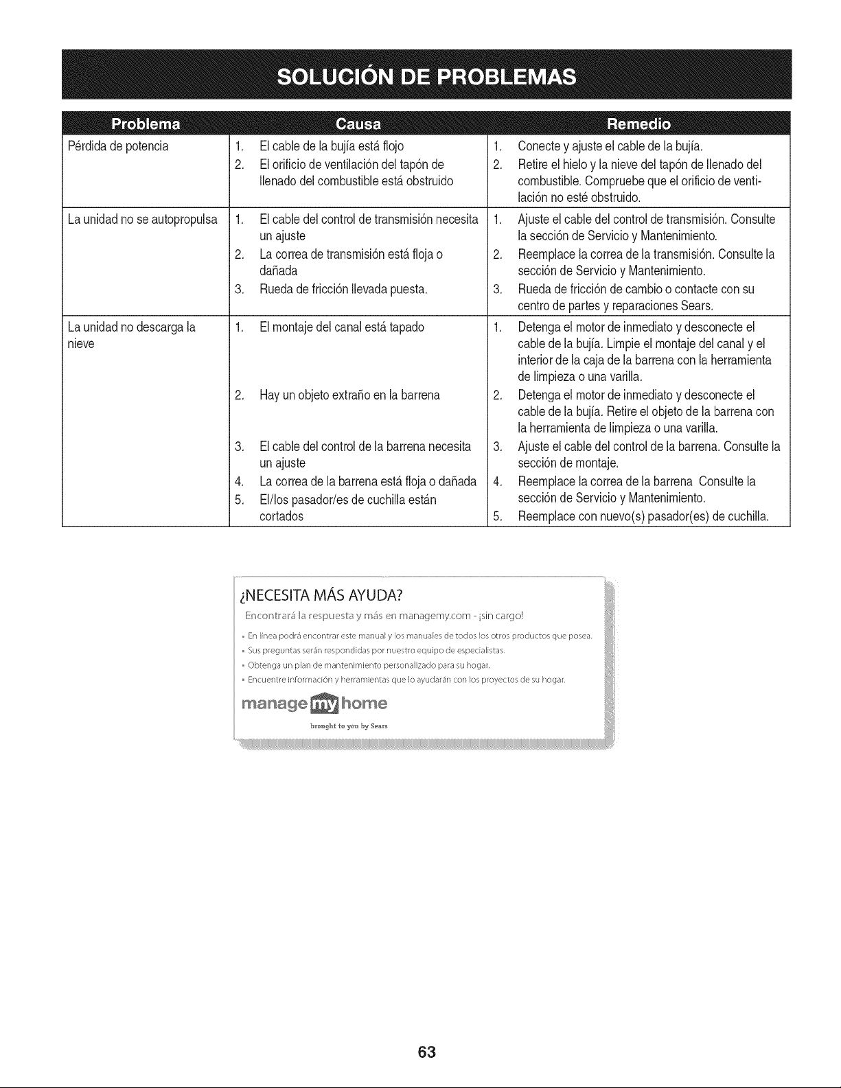
Perdidadepotencia 1. El cablede la bujfaest&flojo
2. El orificiode ventilaci6ndel tap6nde
Ilenadodel combustibleest,. obstruido
1. El cabledel controlde transrnisi6nnecesita
unajuste
2. La correade transrnisi6nest,.flojao
daSada
3. Ruedade fricci6nIlevadapuesta.
1. El rnontajedel canalest,. tapado
La unidadnose autopropulsa
La unidadnodescargala
nieve
2. Hay un objetoextraSoen la barrena
3. El cabledel controlde la barrenanecesita
unajuste
4. La correade la barrenaest,. flojao daSada
5. El/los pasador/esde cuchillaest_.n
cortados
1. Conectey ajusteel cablede la bujfa.
2. Retireel hieloy la nievedel tap6nde Ilenadodel
combustible.Cornpruebeque el orificiode venti-
laci6nnoest_ obstruido.
1. Ajusteel cabledel controlde transrnisi6n.Consulte
lasecci6ndeServicioy Mantenirniento.
2. Reernplacela correade la transrnisi6n.Consultela
secci6nde Servicioy Mantenirniento.
3. Ruedade fricci6nde carnbioo contactecon su
centrode partesy reparacionesSears.
1. Detengael motorde inrnediatoy desconecteel
cabledela bujia. Lirnpieel rnontajedel canaly el
interiorde lacaja dela barrenacon laherrarnienta
delirnpiezao una varilla.
2. Detengael motorde inrnediatoy desconecteel
cabledela bujia. Retireel objetode la barrenacon
laherrarnientade lirnpiezao unavarilla.
3. Ajusteel cabledel controlde la barrena.Consultela
secci6nde rnontaje.
4. Reernplacela correade la barrena Consultela
secci6nde Servicioy Mantenirniento.
5. Reernplacecon nuevo(s)pasador(es)decuchilla.
63
MTD CONSUMER GROUP, iNC. (MTD), el Bordo de Recursos de Aire de California (CARB)
y la Agencia de Protecci6n Medioambiental de Estados Unidos (U. S. EPA)
Declaraci6n de Garantia del Sistema de Control de Emisiones
(Derechos y obligaciones del propietario seg_n la garantia contra defectos)
LACOBERTURADESISTEMADECONTROLDEEMISIONESAPLICABLEA MOTORESCERTIFICADOSCOMPRADOSENCALIFORNIA
EN2005Y A PARTIRDE ENTONCES,QUESON USADOSEN CALIFORNIA,Y HASTAANO2005DE MODELOCERTIFICADOY MOTORES
POSTERIORESQUESON COMPRADOSY USADOSENOTRAPARTEEN LOSESTADOSUNIDOS.
Californiayen otra parteen la Coberturade Garantiade DefectosdeControlde Emisi6nde los EstadosUnidos
El Bordode Recursosde Airede California(CARB),la U.S. EPAy MTDsecomplacenen explicarla garantiadel sistemade controlde emisiones
de su motorparaequipotodo terreno,modelo,aSo2005 y versionesposteriores.EnCalifornia,los nuevosmotorespequeSospara equipotodo
terrenose debendise5ar,fabricary equiparparacumplir conest_.ndaresde antinieblat6xicade estados.En otraparteen los EstadosUnidos,
el nuevonocamino,motoresde ignici6nde chispacertificadospara el modelo2005 y m_.starde,debe encontrarel juego de est_.ndaressimilar
adelantepor los EstadosUnidos.EPA.MTDdebegarantizarel sistemadecontrolde emisionesdesu motorpor el periodode tiempoindicadom&s
abajo,siemprey cuandono hayaexistidousoincorrecto,negligencianimantenimientoinadecuadode su motorpequeBoparaequipotodoterreno.
El sistemadecontrolde emisionespuedeincluirpiezascomo,porejemplo,el carburador,sistemade inyecci6nde combustible,el sistemade
encendido,el catalizador,losdep6sitosdecombustible,abastecedecombustiblelineas, gorrasde combustible,v&lvulas,latas,filtros,mangueras
devapor,abrazaderas,conectoresy otroscomponentesrelacionadoscon lasemisiones.
Dondeexistaunacondici6ncubiertapor la garantia,MTDreparar&su motorpequeBoparaequipotodoterrenosincostoalgunoincluyendoel
diagn6stico,laspiezasy la manode obra.
COBERTURA DE LA GARANTJA DEL FABRICANTE:
Estesistemade controldeemisionesse garantizaporel t@rminodedos a5os.Si algunapiezade su motorrelacionadacon lasemisioneses
defectuosa,MTD reparar&o sustituir&dichapieza.
RESPONSABJLIDADES DEL PROPIETARIO SEGUN LA GARANTJA:
Comopropietariode un motorpequeSode equipotodoterreno,ustedes responsablede realizarel mantenimientonecesarioquefigura enel
manualdel propietario.MTDle recomiendaque conservetodos los recibosquecubrenlos serviciosde mantenimientodel motorpeque5opara
equipotodoterreno,noobstanteIo cual MTDno podr&denegarel cumplimientode la garantiaQnicamenteporla falta de reciboso por su imposibi-
lidadde asegurarquese realizar_.ntodoslos serviciosde mantenimientoprogramado.
Comopropietariodel motorpeque5oparaequipotodo terreno,sinembargo,ustedtambi@ndebesaberque MTDpuede denegarla coberturade la
garantiasi su motorpeque5oparaequipotodoterrenoo unapiezadel mismofallandebidoa usoincorrecto,negligencia,mantenimientoindebido
o a modificacionesnoaprobadas.
Ustedes responsablede presentarla cortadorade cespedal centrode distribuci6no de mantenimientode MTDCONSUMERGROUP,INC.tan
prontocomoaparecierael problem& Lasreparacionescubiertaspor la garantiasedeben Ilevaracabo en un lapsorazonableque noexcedade
30dias. Si desearealizaralgunaconsultacon respectoa la coberturade lagarantia,debeponerseencontactocon su distribuidorlocalde MTD.
Paracomunicarseconla LineadeAsistenciaal Clientede Distribuidoresde MTD,Ilameal nQmero(877)282-8684.
REQUERJMJENTOS DE GARANTJA SOBRE DEFECTOS PARA MOTORES PEQUENOS DE EQUJPO TODO TERRENO
DE 1995YVERSJONES POSTERJORES:
Estasecci6nse aplicaa motorespeque5osdeequipotodo terrenode 1995y versionesposteriores.El periodode garantiacomienzaa partirde la
fechaen queel motoro el equipo seentreganal compradorfinal.
(a) Coberturade la garantiacontraemisionesgenerales
MTDgarantizaal compradorfinaly acada compradorsubsiguienteque el motor:
(1)hasido diseSado,construidoy equipadode maneraque cumplacontodas las regulacionesvigentesadoptadaspor el Departamentode los
RecursosdeAire envirtuda suautoridadconferidaen los capitulos1 y 2, Parte5, Divisi6n26 del C6digode Saludy Seguridad;y
(2)est,. librede defectosen los materialesyen la manode obra que causenla falla deunapiezabajogarantiaque seaid@nticaentodoslos
aspectosmaterialesa la piezacomo aparecedescriptaen la aplicaci6ndel fabricantedel motorparacertificaci6npor un periodode dos a5os.
_arantia sobre piezasrelacJonadasconemisJonesse interpretar_,de la sJguientemanera:
(1)Cualquierpiezacubierta por garantiaque no est@programadapara su reemplazosegQnel mantenimientorequeridoenlas instrucciones
escritasdela Subsecci6n(c) debeestargarantizadapor un periodode garantiadefinidoen la Subsecci6n(a)(2). Si la piezafalladurante
el periododecoberturade la garantia,la mismaser_.reparadao reemplazadapor MTD de acuerdocon la Subsecci6n(4) a continuaci6n.
Cualquierpiezareparadao reemplazadasegQnlagarantiasegarantizarB,porel restodelperiodode garantia.
(2) Cualquierpiezacubiertapor garantiaque est@programadasolopara inspecci6nregularen las instruccionesescritasde la Subsecci6n
(c) debe estargarantizadapor un periododegarantiadefinidoenla Subsecci6n(a) (2). Unadeclaraci6nen dichasinstruccionesporescrito
alefectode "reparaci6no reemplazosegQnseanecesario"no reducir_,elperiodode coberturade la garantia.Cualquierpiezareparadao
reernplazadasegQnlagarantiasegarantizar_,porelrestodelperiododegarantia.
(3) Cualquierpiezagarantizadaqueest_prograrnadaparareernplazosegQnelrnantenirnientorequeridodeconforrnidadconlasinstruc-
clonesescritasdelaSubsecci6n(c)segarantizaporelperiododetiernpoanterioralaprirnerafechadereernplazoprograrnadaparaesa
pieza.Silapiezafallaantesdelprimerreernplazoprogramatic,larnisrnaser_.reparadaoreernplazadaporMTDdeacuerdoconlaSubsecci6n
(4)acontinuaci6n.Cualquierpiezareparadaoreernplazadabajogaranfiasegarantizar_,porelrestodelperiodoanterioralprimerreernplazo
programaticpuntualparaesapieza.
(4)Lareparaci6noelreernplazodecualquierpiezagarantizadadeconforrnidadconlasdisposicionesdelagaranfiaqueaquiseestipulase
deberealizarenuncentrodegaranfiasincostoalgunoparaelpropietario.
(5)SinperjuiciodelasdisposicionesdelaSubsecci6n(4)anterior,losserviciosoreparacionescubiertosporlagaranfiadebensersurnin-
istradosportodosloscentrosdedistribuci6ndeMTDquetenganlafranquiciapararealizarreparacionesyrnantenirnientoalosrnotoresen
cuesti6n.
(6)ElpropietarionodebeafrontarningQncargoparatrabajosdediagn6sticoqueIlevenalaconclusi6ndequeunapiezabajogaranfiapresenta
efectivarnentedefectos,siernpreycuandodichodiagn6sticoseaIlevadoacaboenuncentrocubiertoporlagarantia.
(7)Elfabricantedelmotoresresponsableporda_oscausadosaotroscornponentesdernotoresderivadosdelafallabajogaranfiadecualquier
piezagarantizada.
(8)DurantetodoelperiododegaranfiadelmotordefinidoenlaSubsecci6n(a)(2),MTDrnantendr_,unsurninistrodepiezascubiertaspor
garantiasuficienteparasatisfacerladernandaesperadaparatalespiezas.
(9)Cualquierpiezadereernplazosepodr_,usarparaelcurnplirnientodelrnantenirnientooreparacionesbajogaranfia,ysesurninistrar_,sin
cargoalpropietario.Dichousonoreducir_,lasobligacionesdegarantiadeMTD.
(10)Nosepodr_.nusarpiezasadicionalesnirnodificadasquenoest_nexentasdeacuerdoconelDepartarnentodelosRecursosdelAire(Air
ResourcesBoard).Elusodepiezasadicionalesornodificadasnoexentasser_.causasuficienteparaanularunreclarnobajogaranfiarealizado
deacuerdoconestearticulo.Elfabricantedelmotornotendr_,responsabilidad,enconforrnidadconestearticulo,degarantizarfallasdepiezas
garantizadasquefuerencausadasporelusodeunapiezanoexentaadicionalornodificada.
.(c)MTDincluir_,unacopiade lasiguientelistade piezasbajogarantiacontra ernisionescon cadanuevomotor,utilizandolas partesde la lista
a_plicablesal motor.
(1)Sisternadernedici6ndecombustible
• Sisternade rnejorapara inicioen frio (cebadosuave)
• Carburadory cornponentesinternos
• Bornbade combustible
• Dep6sitode combustible
(2) Sisternadeinducci6ndeaire
• Filtrode aire
• Colectorde entrada
(3) Sisternadeencendido
• Bujia(s)
• Sisternade encendidopor magneto
(4)Sisternadeescape
• Catalizador
• SAI (v_Jvulade Ca_a)
(5) Cornponentesvarios utilizadosen el sisternaanterior
• V_Jvulase interruptoresde vado, ternperatura,posici6nsensiblesal tiernpo
• Conectoresy rnontajes
(6)Controlde Evaporative
• Manguerade CombustiblecertificadaparaARB evaporativeernisi6nde 2006.
• Abrazaderasde Manguerade Combustible
• Gorrade combustibleatada
• Latade carb6n
• Lineasde vapor
GD0C-100174Rev.B
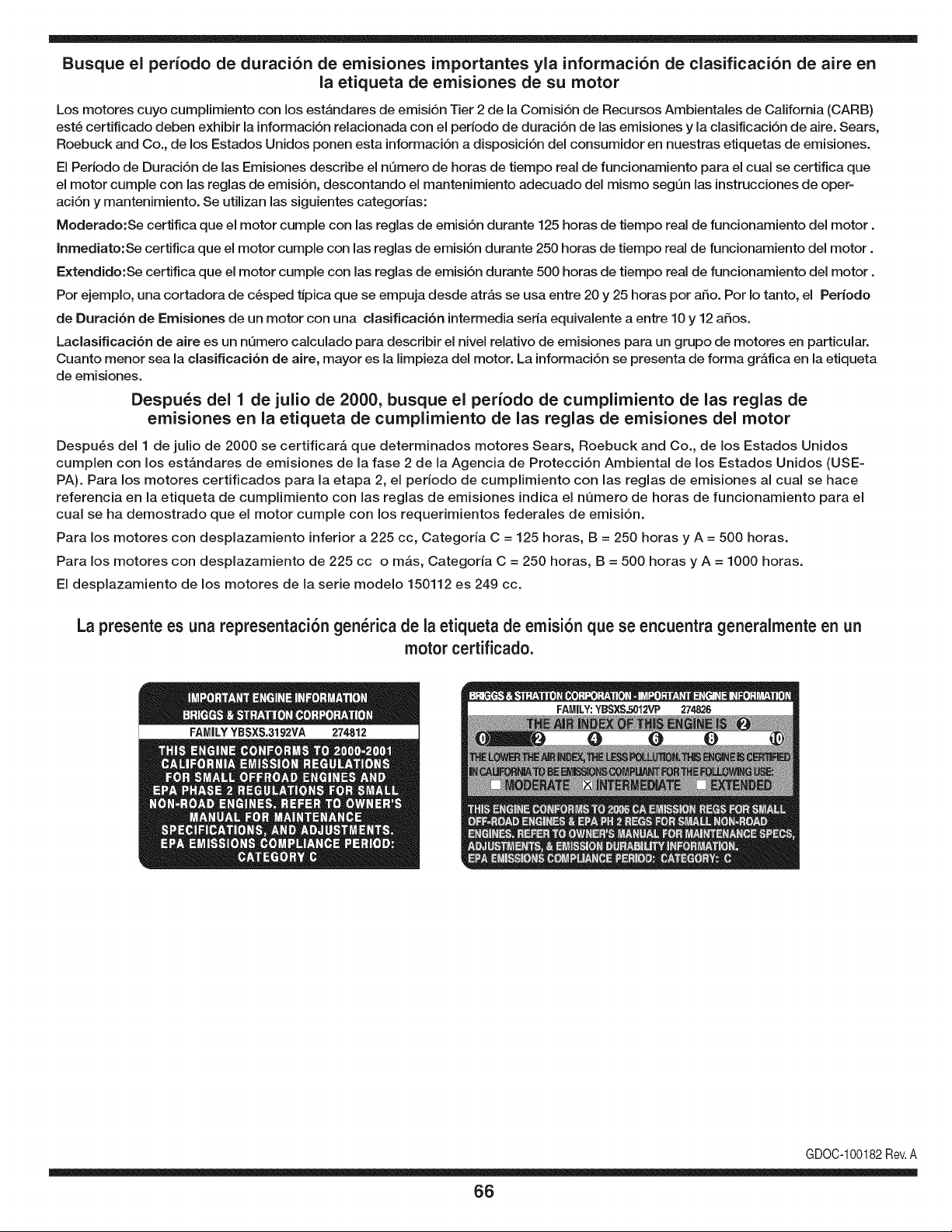
Busque el periodo de duraci6n de emisiones importantes yla informaci6n de clasificaci6n de aire en
la etiqueta de emisiones de su motor
Los motores cuyo cumpiimiento con los estAndares de emisi6n Tier 2 de la Comisi6n de Recursos Ambientales de California (CARB)
est6 certificado deben exhibir la informaci6n relacionada con el perJodo de duraci6n de las emisiones y la clasificaci6n de aire. Sears,
Roebuck and Co., de los Estados Unidos ponen esta informaci6n a disposici6n deJ consumidor en nuestras etiquetas de emisiones.
El Periodo de Duraci6n de las Emisiones describe el nQmero de horas de tiempo real de funcionamiento para el cual se certifica que
el motor cumple con las reglas de emisi6n, descontando el mantenimiento adecuado deJ mismo segQn las instrucciones de oper-
aci6n y mantenimiento. Se utilizan las siguientes categorias:
Moderado:Se certifica que el motor cumpie con las reglas de emisi6n durante 125 horas de tiempo real de funcionamiento deJmotor.
Inmediato:Se certifica que el motor cumple con las reglas de emisi6n durante 250 horas de tiempo real de funcionamiento deJ motor.
Extendido:Se certifica que el motor cumple con las reglas de emisi6n durante 500 horas de tiempo real de funcionamiento deJmotor.
Por ejemplo, una cortadora de c6sped tJpica que se empuja desde atrAs se usa entre 20 y 25 horas por afio. Por Io tanto, el Periodo
de Duraci6n de Emisiones de un motor con una clasificaci6n intermedia seria equivalente a entre 10 y 12 afios.
Laclasificaci6n de aJre es un nQmero calculado para describir eJnivel reiativo de emisiones para un grupo de motores en particular.
Cuanto menor sea Jaclasificaci6n de aire, mayor es JaJimpieza deJ motor. La informaci6n se presenta de forma gr&fica en Jaetiqueta
de emisiones.
Despu_s del 1 de julio de 2000, busque el periodo de cumplimiento de las reglas de
emisiones en la etiqueta de cumplimiento de las reglas de emisiones del motor
Despu_s deJ 1 de julio de 2000 se certificar_, que determinados motores Sears, Roebuck and Co., de los Estados Unidos
cumpien con los estAndares de emisiones de la fase 2 de la Agencia de Protecci6n Ambiental de los Estados Unidos (USE-
PA). Para los motores certificados para la etapa 2, el periodo de cumpiimiento con las reglas de emisiones al cual se hace
referencia en la etiqueta de cumpiimiento con las reglas de emisiones indica el nQmero de horas de funcionamiento para el
cuaJ se ha demostrado que el motor cumpie con los requerimientos federales de emisi6n.
Para los motores con desplazamiento inferior a 225 cc, Categoria C = 125 horas, B = 250 horas y A = 500 horas.
Para los motores con desplazamiento de 225 cc o mAs, Categoria C = 250 horas, B = 500 horas y A = 1000 horas.
El despiazamiento de los motores de la serie modelo 150112 es 249 cc.
La presente es una representaci6n gen_rica de la etiqueta de emisi6n que se encuentra generaimente en un
motor certificado.
FAMILYYBSXS.3192VA 274812
GDOC-100182Rev.A
66
Felicitacionespor haberrealizadouna adquisici6ninteligente.El
productoCraftsman®quehaadquiridoest&diseSadoy fabricado
parabrindarmuchosaSosde funcionamientoconfiable.Perocomo
todoslosproductosa vecespuederequerirde reparaciones.Esen
ese momentocuandoel disponerde un Acuerdode protecci6npara
reparacionesle puedeahorrardineroy problemas.
Acontinuaci6nsedetallanlos puntosincluidosen elAcuerdo:
• Servicio experto prestadopor nuestros10,000especialistasen
reparacionesprofesionales
• Servicio ilimitadosin cargopara laspiezasy la manode obra en
todaslas reparacionescubiertas
• Reemplazodel productohasta 1500d61aressi no es posible
repararelproductocubierto
• Descuentode 10%del precionormaldel servicioy de las piezas
relacionadascon el mismoquenoest_ncubiertasporel acuerdo;
adem&s,10%del precionormalde la verificaci6nde manten-
imientopreventivo
• Ayudar_pidapot tel_fono - Io IlamarnosResoluci6nR_pida- el
apoyotelef6nicode un Chamuscaal representante.Pienseen
nosotroscomoel manual"de undue_ohablador."
Unavezadquiridoel Acuerdo,puedeprogramarelserviciocon
tan s61orealizaruna Ilamadatelef6nica.PuedeIlamaren cualquier
momentodeldia o de la nocheo programarun servicioen linea.
ElAcuerdode Protecci6nde Reparaci6nes una comprasin riesgo.
Si ustedanulapor alguna raz6nduranteel periodode garanfiade
producto,proporcionaremosun reembolsoIleno.O, un reembolso
prorrateadoen cualquiermomentodespu_sdelperiodode garantia
de productoexpira,iAdquieraboysu acuerdode protecci6npara
reparaciones!
Se aplican deterrninadaslimitacionesy exclusiones.Paraobtener
inforrnaci6nadicionaly preciosen los Estados UnidosIlarneal
1-800-827-6655.
El*Coverageen Canad_varia en algunosarticulos.Paradetalles
Ilenosla IlarnadaCharnuscaCanad_en 1-800-361-6665.
Servicio de instalaci6nde Sears
Si deseasolicitarla instalaci6nprofesionalde Searsde aparatos
dom_sticos,dispositivospara abrir portones,calentadoresde agua
y otrosarficulosdom_sticosimportantes,en los EstadosUnidoso
Canad_Ilameal 1-800-4-MY-HOME®.
67

Your Home
For expert troubleshooting and home solutions advice:
www.managemyhome.com
For repair - in your home - of all major brand appliances,
lawn and garden equipment, or heating and cooling systems,
no matter who made it, no matter who sold it!
For the replacement parts, accessories and
owner's manuals that you need to do-it-yourself.
For Sears professional installation of home appliances
and items like garage door openers and water heaters.
1-800-4-MY-HOME ® (1-800-469-4663)
Call anytime, day or night (U.S.A. and Canada)
www.sears.com www.sears.ca
Our Home
For repair of carry-in items like vacuums, lawn equipment,
and electronics, call anytime for the location of your nearest
Sears Parts & Repair Service Center
1-800-488-1222 (U.S.A.) 1-800-469-4663 (Canada)
www.sears.com www.sears.ca
To purchase a protection agreement on a product serviced by Sears:
1-800-827-6655 (U.S.A.) 1-800-361-6665 (Canada)
Para pedir servicio de reparaci6n
a domicilio, y para ordenar piezas:
1-888-SU-HOGAR ®
(1-888-784-6427)
Au Canada pour service en fran£ais:
1-800-LE-FOYER M°
(1-800-533-6937)
www.sears.ca
® Registered Trademark / TMTrademark / SM Service Mark of Sears Brands, LLC
SM
® Marca Registrada / TMMarca de F&brica / Marca de Servicio de Sears Brands, LLC
MCMarque de commerce / MD Marque depos6e de Sears Brands, LLC © Sears Brands, LLC


