Loading ...
Loading ...
Loading ...
II Illl!lllllllllllllll II Ull Illllll Ill I II Ill Illll - II
I
_tslmltm_ forthe_)
i I I I JllllllIItllltIItIllll I Ill I I II
L itqlglP_
_ _'s°M_ z_s_ d_.Zof_dtohctp_u
.asScm_€the toolandio provideitssafeoperation, it is
_ dm _ readtl_ endremanual_ I_omc
familiar_iththetooli_.foleyoubeginassembly.
H .......... i!,.i
H
ii i i
B. ASSEMBLY STEPS
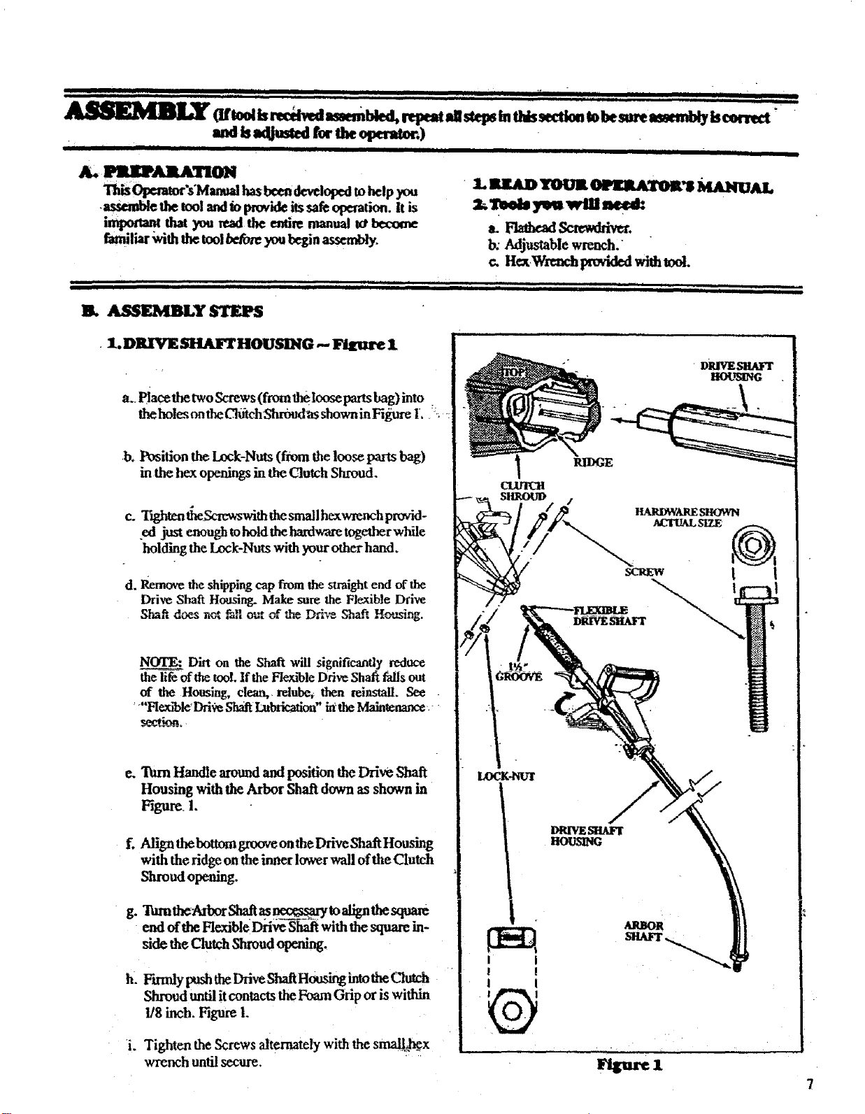
• 1. DR/VE SHAI_ HOUSING .-- Figure 1
a.. Piacethe two Screws (from the loose parts bag) into .
theholesontheClmchShr6udasshowninFi_e 1. L
.b.
Position the Ix_k:Nuts (from the loose parts bag)
in the hex openings in the Clutch Shroud.
c. T_hten tim_wwswith thesmall hexwrench provid-
ed just enough tohold thehardware together while
holding the Lock-Nuts with your other hand.
d. Remove the shipping cap from the straight end of the
Drive Sha_ Housing. Make sure the Flexible Dri'_x:
Shaft d,_ not f_l out r_,_-_ _
NOTE: Dirt on the Shaft will significantly reduce
_of the tool. If the Flenu'bleDrive Shaft fails out
of the Housing, clean,, relube_ then reinstall. See
Ftexa'bleDri_?eShaft Lubricalicm" ia the Maintenance .-
r_-t.ion.
e.
g_
h_
i.
"lMmHandle around and position the Drive Shaft
Housing with the Arbor Shaft down as shown in
Figure. 1.
Align the bottom glXXWeon the Drive Shaft Housing
with the ridge on the inner lower wall of the Clutch
Shroud opening.
_theAex,rS_. _ _to ati_thesqua_
end of the FlexibleDriveShaft with the square in-
side theClutch Shroud opening.
Shroud until itcontacts the Foam Grip or is within
1/8 inch. Figure 1.
Tighten the Screws alternately with the smal[kcx
wrench until secure.
II iii II IIII II
I. luta_ l'OOIt _'g Ma.tetlal.
=,a'=a, my.
b. Adjustable wrench."
c. Hot,Wrtnch provided with tool.
,Ill I I ,,I, I ,,ll II I
II IIIII Illll_
I I
! !
I I
DmV_SnAlzr
HO_._ING
RIDGE
Igigtlre 1
7
Loading ...
Loading ...
Loading ...