Loading ...
Loading ...
4 5
INSTALLATION REQUIREMENTS INSTALLATION REQUIREMENTS (continued)
Before beginning the installation process, gather all the required tools and parts. Read and
follow the instructions as provided.
IMPORTANT: Remember to remove all the packaging material from the interior and exterior
parts of the oven before connecting the gas or electrical supply.
TOOLS/PARTS NEEDED:
Tape Measure Hammer 15/16" Combination Wrench
Flathead Screwdriver Pipe Wrench 1/4" Drive Ratchet
Phillips Screwdriver Wrench or Pliers 3/8" Nut Driver
Level Marker or Pencil 1/8" (3.2 mm) drill bit (for
wood floors)
Hand or Electric Drill
PARTS SUPPLIED
Check that all parts are included.
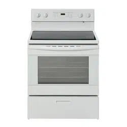
Anti-tip bracket must be securely mounted
to floor or wall.
Thickness of flooring may require longer
screws to anchor bracket to the floor.
A. Anti-tip bracket
B. #10 x 1-7/8" screws (2)
A
B
#10 x 1-7/8" screws (2)
PART YOU WILL NEED (sold separately):
UL Listed Power Cord
LOCATION REQUIREMENTS
IMPORTANT:
• Observe all governing codes and
ordinances.
• Do not obstruct flow of combustion
and ventilation air.
• It is the installer’s responsibility to
comply with installation clearances
specified on the model/serial rating
plate. The Model/Serial rating plate is
located on the oven frame behind the
top left side of the Oven Drawer door.
You can also find the same model/seri-
al rating plate on the back of the oven.
• Recessed installations must provide
complete enclosure of the sides and
rear of the range.
• All openings in the wall or floor where
range is to be installed must be
sealed.
• Do not seal the range to the side
cabinets.
• Cabinet opening dimensions that are
shown must be used.
• Given dimensions are minimum
clearances.
• The floor anti-tip bracket must be
installed. To install the anti-tip bracket
shipped with the range, see “Install
Anti-Tip Bracket” section.
• Grounded electrical supply is required.
See “Electrical Requirements” section.
• Contact a qualified floor covering in-
staller to check that the floor covering
can withstand at least 200°F (93°C).
• Use an insulated pad or ¼" (0.64 cm)
plywood under range if installing range
over carpeting.
IMPORTANT:
TO AVOID DAMAGE TO YOUR CABINETS, CHECK WITH YOUR BUILDER
OR CABINET SUPPLIER TO MAKE SURE THAT THE MATERIALS USED WILL
NOT DISCOLOR, OR SUSTAIN OTHER DAMAGE.
This oven has been designed in accor-
dance with the requirements of UL and CSA
International and complies with the maxi-
mum allowable wood cabinet temperatures
of 194°F (90°C).
MOBILE HOME INSTALLATION
REQUIREMENT:
When this range is installed in a mobile
home, it must be secured according to the
instructions in this manual.
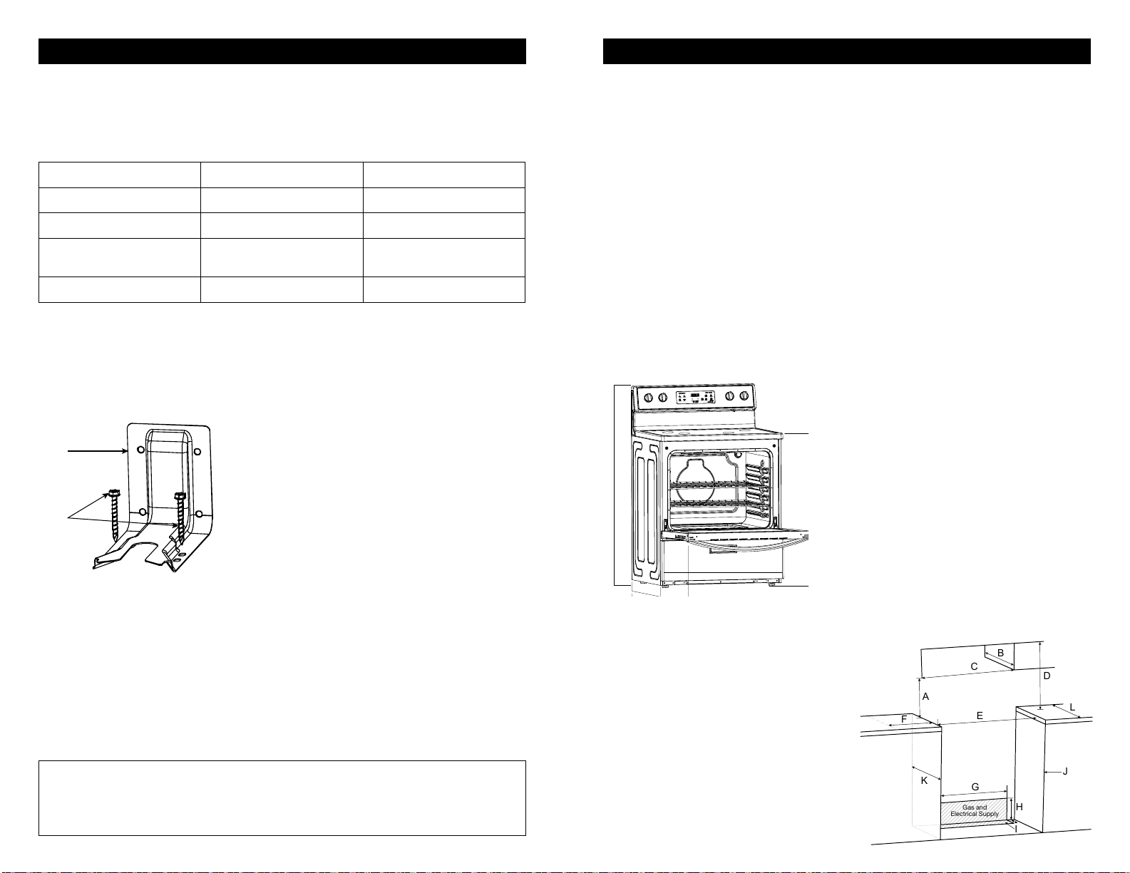
PRODUCT DIMENSIONS
A. 25.63" (65.1 cm) depth. Back of range
to front of cooktop
B. 28.5" (72.4 cm) max. depth with handle
C. 46.26" (117.5 cm) overall height (max.)
with leveling legs
D. 29.87" (75.9 cm) width
E. 35.9" (91.2 cm) cooktop height (max.)
with leveling legs
E
A
B
C
D
IMPORTANT:
Range must be level after installation.
Follow the instructions in the “Level Range”
section. Using the cooktop as a reference
for leveling the range is not recommended.
Range can be raised approximately 1.18" (3
cm) by adjusting the leveling legs.
Front of door and drawer may extend far-
ther forward depending on styling.
CABINET DIMENSIONS
Cabinet opening dimensions shown are for
26" (66.0 cm) countertop depth, 24" (61.0
cm) base cabinet depth and 36" (91.4 cm)
countertop height.
A. 18" (45.7 cm) upper side cabinet to
countertop
B. 13" (33 cm) maximum upper cabinet
depth
C. 30-1/8" (76.5 cm) minimum opening
width
D. For minimum clearance to top of cook-
top, see “*NOTE” below.
E. 30-1/8" (76.5 cm) minimum opening
width
F. 3" (7.6 cm) minimum clearance from
both sides of range to side wall or
other combustible material.
G. 27" (68.7 cm)
H. 7-4/5" (19.8 cm)
I. 3-1/5" (8 cm)
J. Cabinet door or hinges should not
extend into the cutout.
K. 24" (61.0 cm) base cabinet depth
L. 26" (66.0 cm) tabletop width of base
cabinet
*NOTE: Allow 30" minimum clearance
between surface units and bottom of un-
protected wood or metal cabinet, or allow
a 24" (61.0 cm) minimum when bottom
of wood or metal cabinet is protected by
no less than 1/4" (0.64 cm) thick flame
retardant millboard covered with not less
than No 28 MSG sheet metal [0.015" (0.4
mm)], 0.015" (0.4 mm) thick stainless steel,
0.024" (0.6 mm) aluminum or 0.020" (0.5
mm) copper.
Gas and
Electrical Supply
E
G
F
K
H
I
D
L
J
C
A
B
Loading ...
Loading ...
Loading ...