
Operator's Manual
Snow Thrower
11 Horsepower
Electric Start
30-inch Dual Stage
Model 536.881112
CAUTION: Before using this
product, read this manual and
follow all of its Safety Rules and
Operating Instructions.
-I=..rT=...°l-
Manual del usario
Quitanieves
de 30 pulgadas
11 caballos de fuerza (hp)
Bietapico
Arranque el_ctrico
Modelo 536.881112
PRECAUCION: Antes de usar este producto,
lea este manual y siga todas las reglas de
seguridad e instrucciones de operaci6n.
Sears, Roebuck and Co., Hoffman Estates, IL 60179 U.S.A.
F-011047L www.sears.com/craftsman
NnIL,'q:] ! =l[o]d[_o_ _Innl=1_In_
WARRANTY STATEMENT ......
SAFETY RULES ...............
INTERNATIONAL SYMBOLS . ..
ASSEMBLY ...................
OPERATION ..................
MAINTENANCE ...............
SERVICE AND ADJUSTMENT ..
2 STORAGE .................... 32
2 TROUBLE SHOOTING CHART.. 33
4 REPAIR PARTS ............... 37
6 ENGINE REPAIR PARTS ....... 56
12 SPANISH (ESPAI_IOL) .......... 64
19 PARTS ORDERING/SERVICE ..
22 BACK COVER
LIMITED TWO-YEAR WARRANTY ON CRAFTSMAN SNOW THROWER
For two years from the date of purchase, when this Craftsman Snow thrower is maintained,
lubricated, and tuned up according to the operating and maintenance instructions in the
owner's manual, Craftsman will repair, free of charge, any defect in material or workman-
ship.
If this Craftsman Snow thrower is used for commercial or rental purposes, this warranty ap-
plies for only 90 days from the date of purchase.
This warranty does not cover the following:
Items which become worn during normal use, such as spark plugs, drive belts and shear
pins.
Repair necessary because of operator abuse or negligence, including bent crankshafts
and the failure to maintain the equipment according to the instructions contained in the
owner's manual.
WARRANTY SERVICE IS AVAILABLE BY RETURNING THE CRAFTSMAN SNOW
THROWERTO THE NEAREST CRAFTSMAN SERVICE CENTER/DEPARTMENT IN
THE UNITED STATES. THIS WARRANTY APPLIES ONLY WHILE THIS PRODUCT IS
IN USE IN THE UNITED STATES.
This warranty gives you specific legal rights, and you may also have other rights which may
vary from state to state.
Sears, Roebuck and Co., D817WA, Hoffman Estates. IL 60179
_k OOK FOR THIS SYMBOL TO POINT OUT IMPORTANT SAFETY PRECAUTIONS.
IT MEANS-- ATTENTION!!! BECOME ALERT!!! YOUR SAFETY IS INVOLVED.
Engine Exhaust, some of its constituents, and
certain vehicle components contain or emit
chemicals known to the State of California to
cause cancer and birth defects or other repro-
ductive harm.
Battery posts, terminals and related accessories
contain lead and lead compounds, chemicals
known to the State of California to cause cancer
and birth defects or other reproductive harm.
WASH HANDS AFTER HANDLING.
_k ARNING: Always discon-
nect the spark plug wire
and place it where it cannot
make contact with spark plug to
prevent accidental starting during:
Preparation, Maintenance, or Stor-
age of your snow thrower.
IMPORTANT: Safety standards re-
quire operator presence controls to
minimize the risk of injury. Your snow
thrower is equipped with such controls.
Do not attempt to defeat the function of
the operator presence control under any
circumstances.
F-O11047L 2
TRAINING
1. Read the operating and service instruction
manual carefully. Be thoroughly familiar
with the controls and the proper use of the
equipment. Know how to stop the unit and
disengage the controls quickly.
2. Never allow children to operate the equip-
ment. Never allow adults to operate the
equipment without proper instruction.
3. Keep the area of operation clear of all per-
sons, particularly small children and pets.
4. Exercise caution to avoid slipping or falling
especially when operating in reverse.
PREPARATION
1. Thoroughly inspect the area where the
equipment is to be used and remove all
doormats, sleds, boards, wires, and other
foreign objects.
2. Disengage all clutches before starting the
engine (motor).
3. Do not operate the equipment without
wearing adequate winter outer garments.
Wear footwear that will improve footing on
slippery surfaces.
4. Handle fuel with care; it is highiy flam-
mable.
a. Use an approved fuel container.
b. Never remove fuel tank cap or add fuel
to a running engine (motor) or hot en-
gine (motor).
c. Fill fuel tank outdoors with extreme
care. Never fill fuel tank indoors.
d. Replace fuel cap securely and wipe up
spilled fuel.
e. Never store fuel or snow thrower with
fuel in the tank inside of a building
where fumes may reach an open flame
or spark.
f. Check fuel supply before each use, al-
lowing space for expansion as the heat
of the engine (motor) and/or sun can
cause fuel to expand.
5. For all units with electric starting motors
use electric starting extension cords certi-
fied CSA/UL Use only with a receptacle
that has been installed in accordance with
iocal inspection authorities.
6. Adjust the snow thrower height to clear
gravel or crushed rock surface.
7. Never attempt to make any adjustments
while the engine (motor) is running (except
when specifically recommended by manu-
facturer).
8. Let engine (motor) and snow thrower ad-
just to outdoor temperatures before starting
to clear snow.
F-011047L
Always wear safety glasses or eye shields
during operation or while performing an ad-
justment or repair to protect eyes from
foreign objects that may be thrown from the
snow thrower.
OPERATION
1. Do not operate this machine if you are tak-
ing drugs or other medication which can
cause drowsiness or affect your ability to
operate this machine.
2. Do not use this machine if you are mentally
or physically unable to operate this ma-
chine safely.
3. Do not put hands or feet near or under ro-
tating parts. Keep clear of the discharge
opening at all times.
4. Exercise extreme caution when operating
on or crossing gravel drives, walks or
roads. Stay alert for hidden hazards or
traffic.
5. After striking a foreign object, stop the en-
gine (motor), remove the wire from the
spark plug, thoroughly inspect snow
thrower for any damage, and repair the
damage before restarting and operating
the snow thrower.
6. If the unit should start to vibrate abnormal-
ly, stop the engine (motor) and check im-
mediately for the cause. Vibration is
generally a warning of trouble.
7. Stop the engine (motor) whenever you
leave the operating position, before un-
clogging the auger/impeller housing or dis-
charge chute and when making any
repairs, adjustments, or inspections.
8. When cleaning, repairing, or inspecting,
make certain the auger/impeller and all
moving parts have stopped and all controls
are disengaged. Disconnect the spark plug
wire and keep the wire away from the spark
plug to prevent accidental starting.
9. Take all possible precautions when leaving
the snow thrower unattended. Disengage
the auger/ impeller, stop engine (motor),
and remove key.
10. Do not run the engine (motor) indoors, ex-
cept when starting the engine (motor) and
for transporting the snow thrower in or out
of the building. Open the outside doors; ex-
haust fumes are dangerous (containing
CARBON MONOXIDE, an ODORLESS
and DEADLY GAS).
11. Do not clear snow across the face of
slopes. Exercise extreme caution when
changing direction on slopes. Do not at-
tempt to clear steep slopes.
12. Never operate the snow thrower without
proper guards, plates or other safety pro-
tective devices in place.
13.Neveroperatethesnowthrowernearen-
closures,automobiles,windowwells,
drop-offs,andthelikewithoutproperad-
justmentofthesnowdischargeangle.
Keepchildrenandpetsaway,
14.Donotoverloadthemachinecapacityby
attemptingtoclearsnowattoofastarate.
15.Neveroperatethemachineathightrans-
portspeedsonslipperysurfaces.Lookbe-
hindandusecarewhenbackingup.
16.Neverdirectdischargeatbystandersor
allowanyoneinfrontoftheunit.
17.Disengagepowertothecollector/impel]er
whensnowthroweristransportedornotin
use.
18. Use only attachments and accessories ap-
proved by the manufacturer of the snow
thrower (such as tire chains, electric start
kits, ect.),
19. Never operate the snow thrower without
good visibility or light, Always be sure of
your footing and keep a firm hold on the
handles. Walk;never run,
20. Do not over-reach, Keep proper footing
and balance at all times.
21, Do not attempt to use snow thrower on a
roof.
MAINTENANCE AND
STORAGE
1, Check shear bolts and other bolts at fre-
quent intervals for proper tightness to be
sure the equipment is in safe working
condition,
2. Never store the snow thrower with fuel in
the tank inside a building where ignition
sources are present such as hot water and
space heaters, clothes dryers, and the like.
Allow the engine (motor) to cool before
storing in any enclosure.
3. Always refer to operator's guide instruc-
tions for important details if the snow
thrower is to be stored for an extended
period.
4. Maintain or replace safety and instruction
labels, as necessary.
5. Run the snow thrower a few minutes after
throwing snow to prevent freeze-up of the
auger/impeller.
_lb WARNING: This snow thrower is
for use on sidewalks, driveways
and other ground level surfaces.
Caution should be exercised while using on
steep sloping surfaces. DO NOT USE
SNOW THROWER ON SURFACES ABOVE
GROUND LEVEL such as roofs of resi-
dences, garages, porches or other such
structures or buildings.
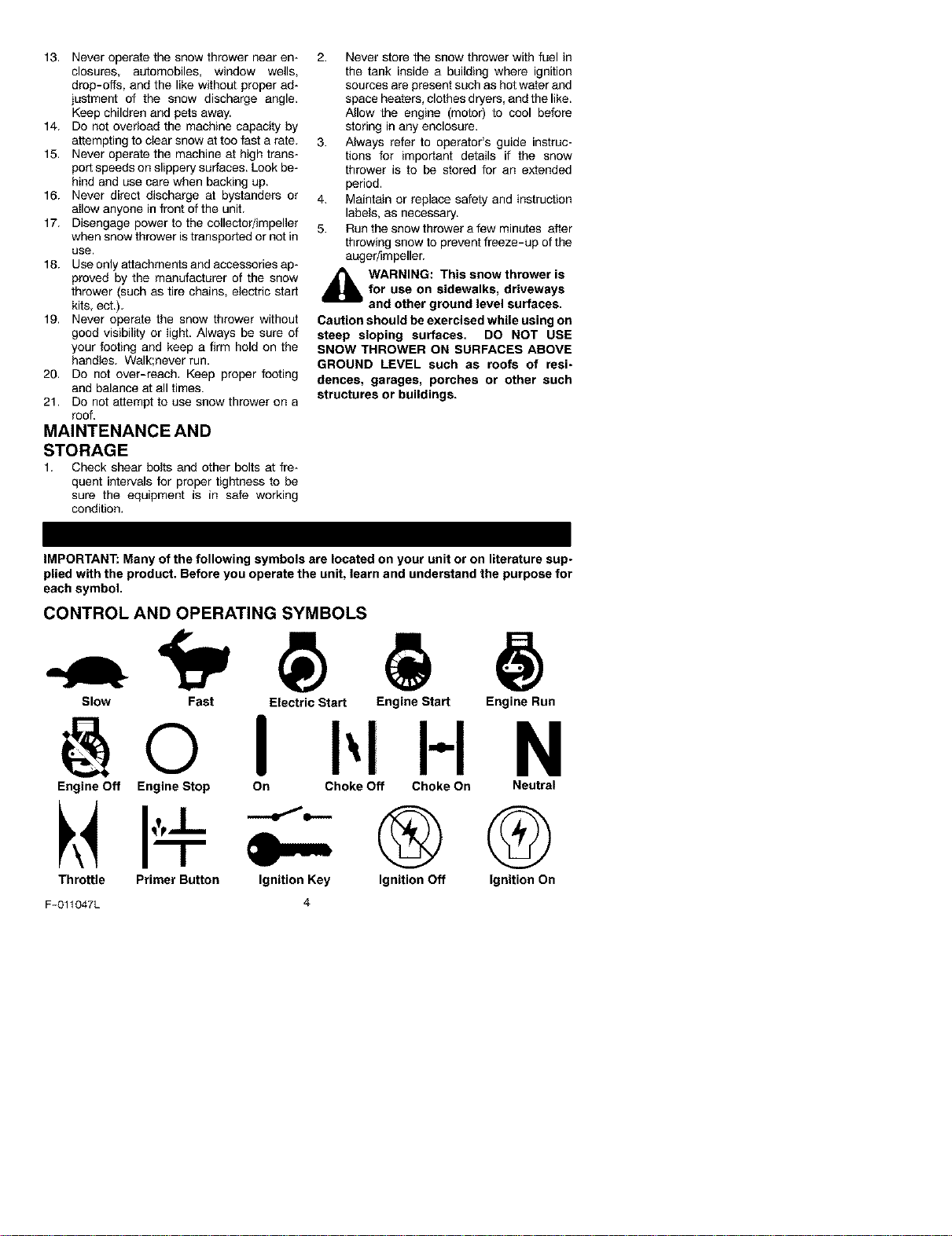
iMPORTANT: Many of the following symbols are located on your unit or on literature sup-
plied with the product. Before you operate the unit, learn and understand the purpose for
each symbol.
CONTROL AND OPERATING SYMBOLS
Slow Fast Electric Start Engine Start Engine Run
I-I N
Engine Off Engine Stop On Choke Off Choke On
U
Throttle Primer Button
Ignition Key
4
F-011047L
Neutral
®Q
Ignition Off Ignition On
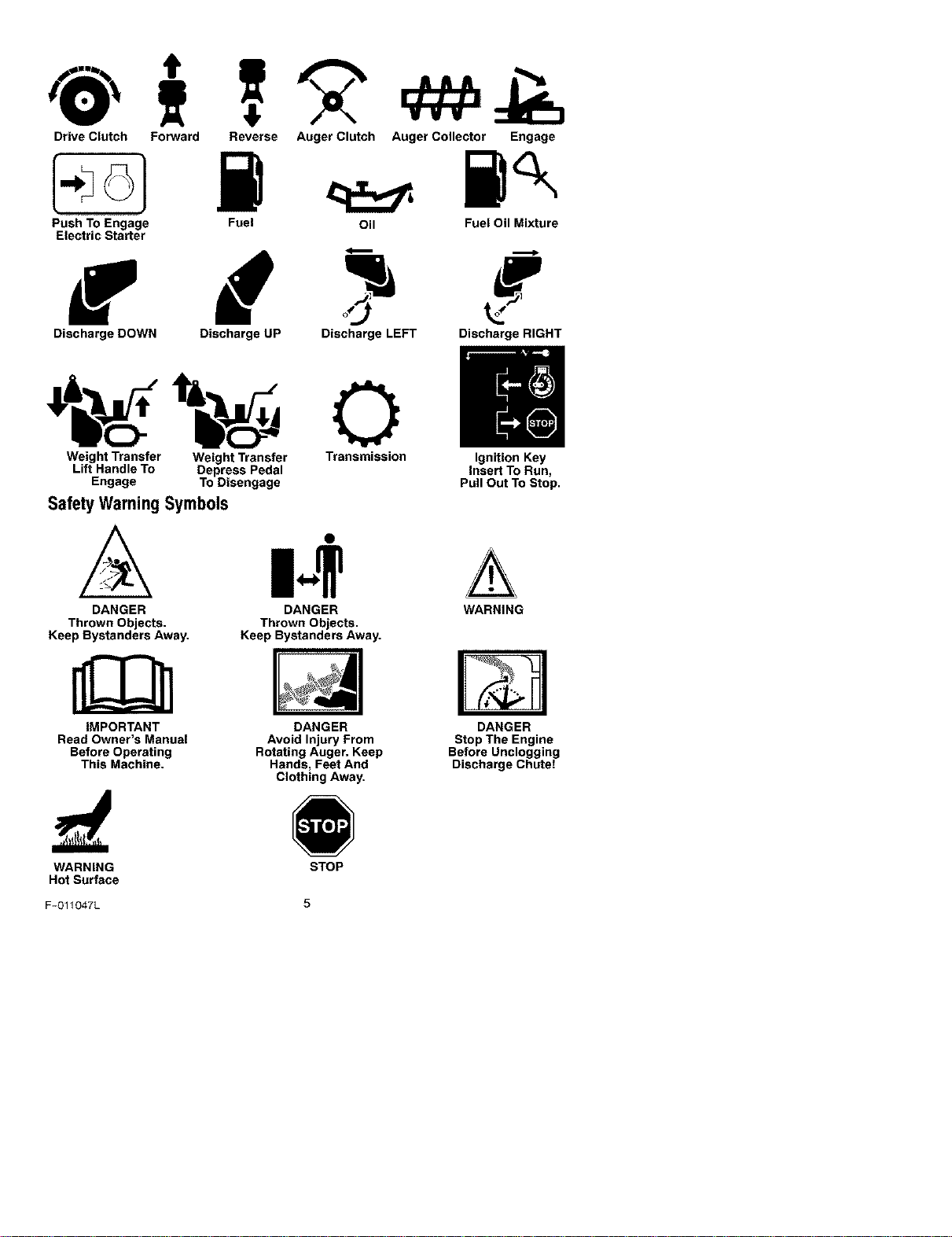
Drive Clutch Forward Reverse Auger Clutch Auger Collector Engage
Push To Engage
Electric Starter
Fuel Oil FueI OilMixture
Discharge DOWN Discharge UP Discharge LEFT Discharge RIGHT
Weight Transfer Weight Transfer Transmission Ignition Key
Lift Handle To Depress Pedal Insert To Run,
Engage To Disengage Pull Out To Stop.
Safety WarningSymbols
DANGER
Thrown Objects.
Keep Bystanders Away.
IMPORTANT
Read Owner's Manual
Before Operating
This Machine.
DANGER
Thrown Objects.
Keep Bystanders Away.
DANGER
Avoid Injury From
Rotating Auger. Keep
Hands, Feet And
Clothing Away.
WARNING
DANGER
Stop The Engine
Before Unclogging
Discharge Chute!
WARNING
Hot Surface
STOP
F-O11047L 5
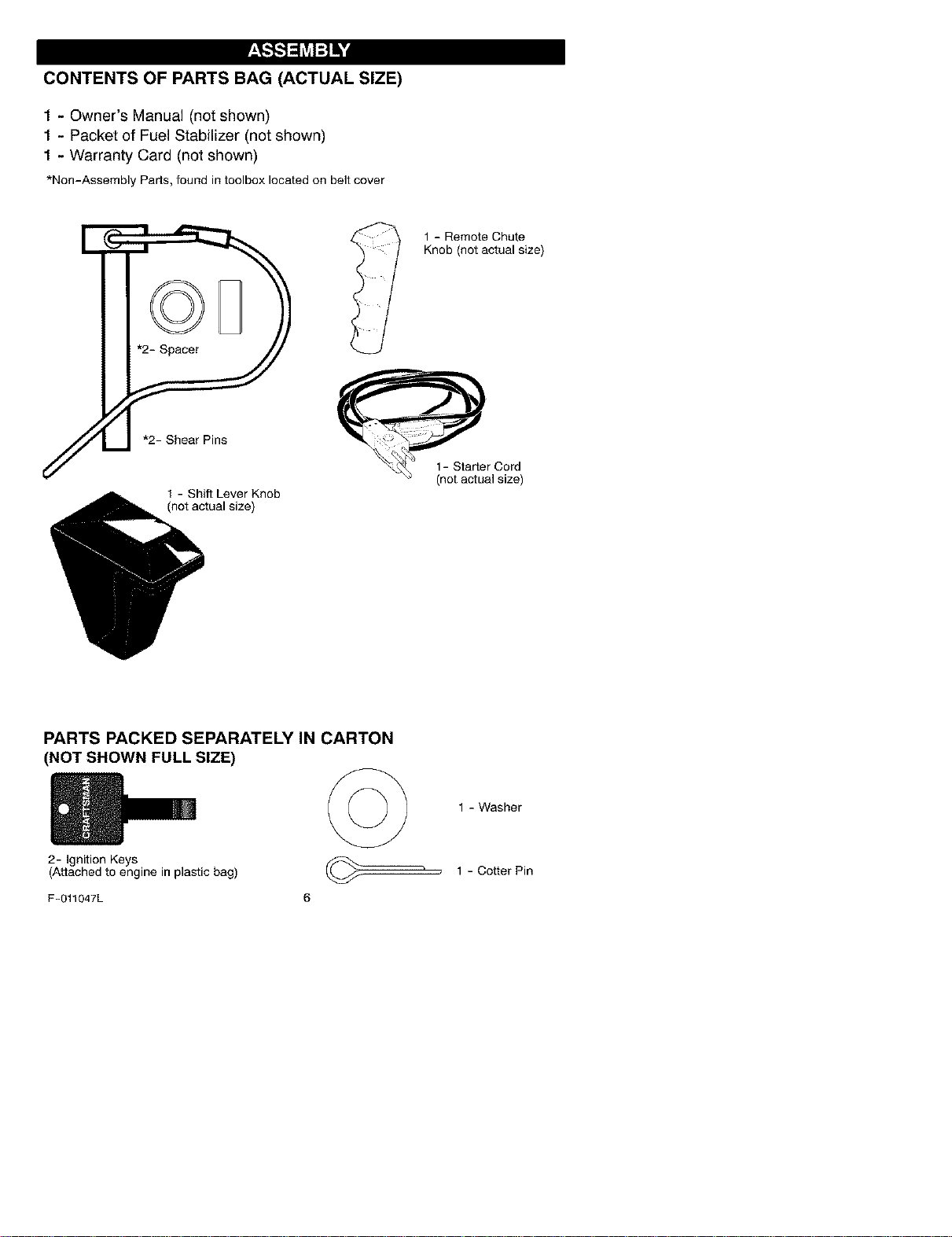
CONTENTS OF PARTS BAG (ACTUAL SIZE)
1 - Owner's Manual (not shown)
1 - Packet of Fuel Stabilizer (not shown)
1 - Warranty Card (not shown)
*Non-Assembly Parts,foundintoolboxlocatedon beltcover
1 - Shift Lever Knob
(not actual size)
l 1 - Remote Chute
Knob (not actual size)
PARTS PACKED SEPARATELY IN CARTON
(NOT SHOWN FULL SIZE)
2- Ignition Keys
(Attached to engine in plastic bag)
1 - Washer
1 - Cotter Pin
F-011047L 6
_,"_ _hVJl:11_•&
4_lb WARNING: Always wearsafety glasses or eye shields
while assembling snow
thrower.
TOOLS REQUIRED FOR
ASSEMBLY
1 - Knife to cut carton
2 - 1/2 inch wrenches
(or adjustable wrenches)
2 - 9/16 inch wrenches
(or adjustable wrenches)
2 - 3/4 inch wrenches
(or adjustable wrenches)
1 - Pliers (to spread cotter pin)
1 - Screwdriver
1 - Measuring tape or ruler
o
Figure 1
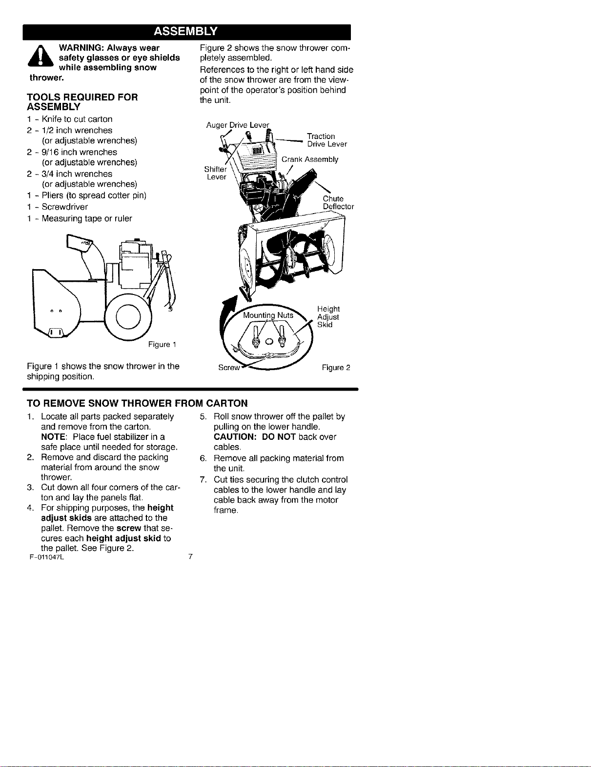
Figure 1 shows the snow thrower in the
shipping position.
Figure 2 shows the snow thrower com-
pletely assembled.
References to the right or left hand side
of the snow thrower are from the view-
point of the operator's position behind
the unit.
Auger DriveLever
__ Traction
_ DriveLever
CrankAssembly
S,h, e : /
I Chute
Deflector
Height
. Adjust
Skid
Scre_ Figure 2
TO REMOVE SNOW THROWER FROM CARTON
1. Locate all parts packed separately
and remove from the carton.
NOTE: Place fuel stabilizer in a
safe place until needed for storage.
2. Remove and discard the packing
material from around the snow
thrower.
3. Cut down all four corners of the car-
ton and lay the panels flat.
4. For shipping purposes, the height
adjust skids are attached to the
pallet. Remove the screw that se-
cures each height adjust skid to
the pallet. See Figure 2.
F-011047L
5. Roll snow thrower off the pallet by
pulling on the lower handle.
CAUTION: DO NOT back over
cables.
6. Remove all packing material from
the unit.
7. Cut ties securing the clutch control
cables to the lower handle and lay
cable back away from the motor
frame.
TO ASSEMBLE THE HANDLE AND
CRANK ASSEMBLY
1. Cut tie holding shift rod to lower
handle and move shifter to the first
forward gear.
2. Cut and discard the plastic tie that
secures the crank assembly.
3. Loosen, but do not remove, the
screws, flatwashers, Iockwashers,
and hex nuts in the upper holes of
the lower handle. See Figure 3.
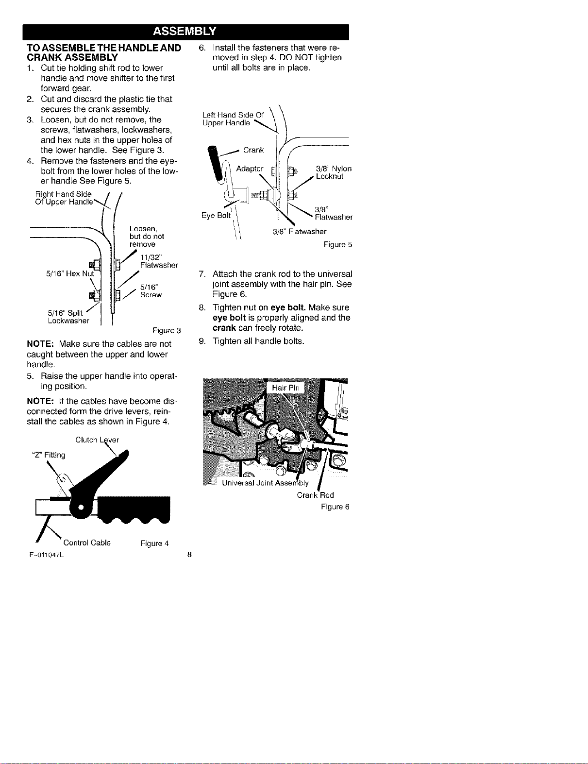
4. Remove the fasteners and the eye-
bolt from the lower holes of the low-
er handle See Figure 5.
Right Hand Side
Of U
Loosen,
but do not
remove
11/32"
Flatwasher
5/
5/16"
Screw
Lookwasher
Figure3
NOTE: Make sure the cables are not
caught between the upper and lower
handle.
5. Raise the upper handle into operat-
ing position.
NOTE: If the cables have become dis-
connected form the drive levers, rein-
stall the cables as shown in Figure 4.
"Z" Fitting
6. Install the fasteners that were re-
moved in step 4. DO NOT tighten
until all bolts are in place.
Left Hand Side Of
Upper Handle _,
3/8" Nylon
Locknut
Eye Boll
3/8"
3/8" Flatwasher
Figure 5
7. Attach the crank rod to the universal
joint assembly with the hair pin. See
Figure 6.
8. Tighten nut on eye bolt. Make sure
eye bolt is properly aligned and the
crank can freely rotate.
9. Tighten all handle bolts.
Crank :od
Figure 6
Control Cable Figure4
F-011047L 8
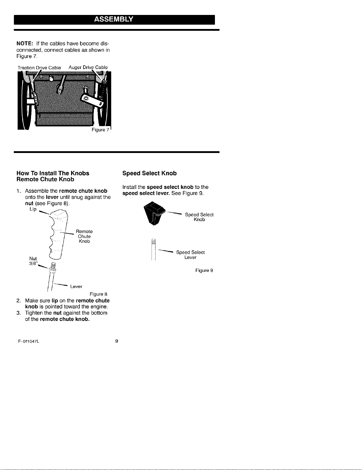
NOTE: If the cables have become dis-
connected, connect cables as shown in
Figure 7.
Traction Drive Cable Auger Drive Cable
How To Install The Knobs
Remote Chute Knob
Figure 7
1. Assemble the remote chute knob
onto the lever until snug against the
nut (see Figure 8).
LIp
Remote
Chute
Knob
Nut
//_--"" Lever
Figure8
2. Make sure lip on the remote chute
knob is pointed toward the engine.
3. Tighten the nut against the bottom
of the remote chute knob,
Speed Select Knob
Install the speed select knob to the
speed select lever. See Figure 9.
Speed Select
Lever
Figure 9
F-011047L 9
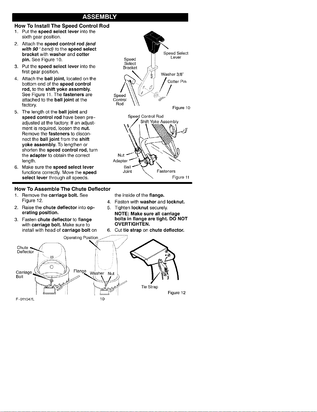
How To Install The Speed Control Rod
1. Put the speed select lever intothe
sixth gear position.
2. Attach the speed control rod (end
with 90 °bend) to the speed select
bracket with washer and cotter
pin. See Figure 10.
3. Put the speed select lever into the
first gear position.
4. Attach the ball joint, located on the
bottom end of the speed control
rod, to the shift yoke assembly.
See Figure 11. The fasteners are
attached to the ball joint at the
factory.
5. The length ot the ball joint and
speed control rod have been pre-
adjusted at the factory. If an adjust-
ment is required, loosen the nat.
Remove the fasteners to discon-
nect the ball joint from the shift
yoke assembly. To lengthen or
shorten the speed control rod, turn
the adapter to obtain the correct
length.
6. Make sure the speed select lever
functions correctly. Move the speed
select lever through all speeds.
Speed Select
Speed Lever
Select
Bracket
Washer 3/8"
Speed /
Control
Rod
Figure 10
Speed Control Rod
Shift YokeAssembly
AdNpUttr% __
Ball-'Y \
Joint _. Fasteners
Figure 11
How To Assemble The Chute Deflector
1. Remove the carriage bolt. See
Figure 12.
2. Raise the chute deflector into op-
erating position.
3. Fasten chute deflector to flange
with carriage bolt. Make sure to
install with head of carriage bolt on
the inside of the flange.
4. Fasten with washer and Iocknut.
5. Tighten Iocknut securely.
NOTE: Make sure all carriage
bolts in flange are tight. DO NOT
OVERTIGHTEN.
6. Cut tie strap on chute deflector.
Operating
Carriage
Bolt
Tie Strap
Figure 12
F-011047L 10
_,,-,I,,',]=I_vjI--I_-I
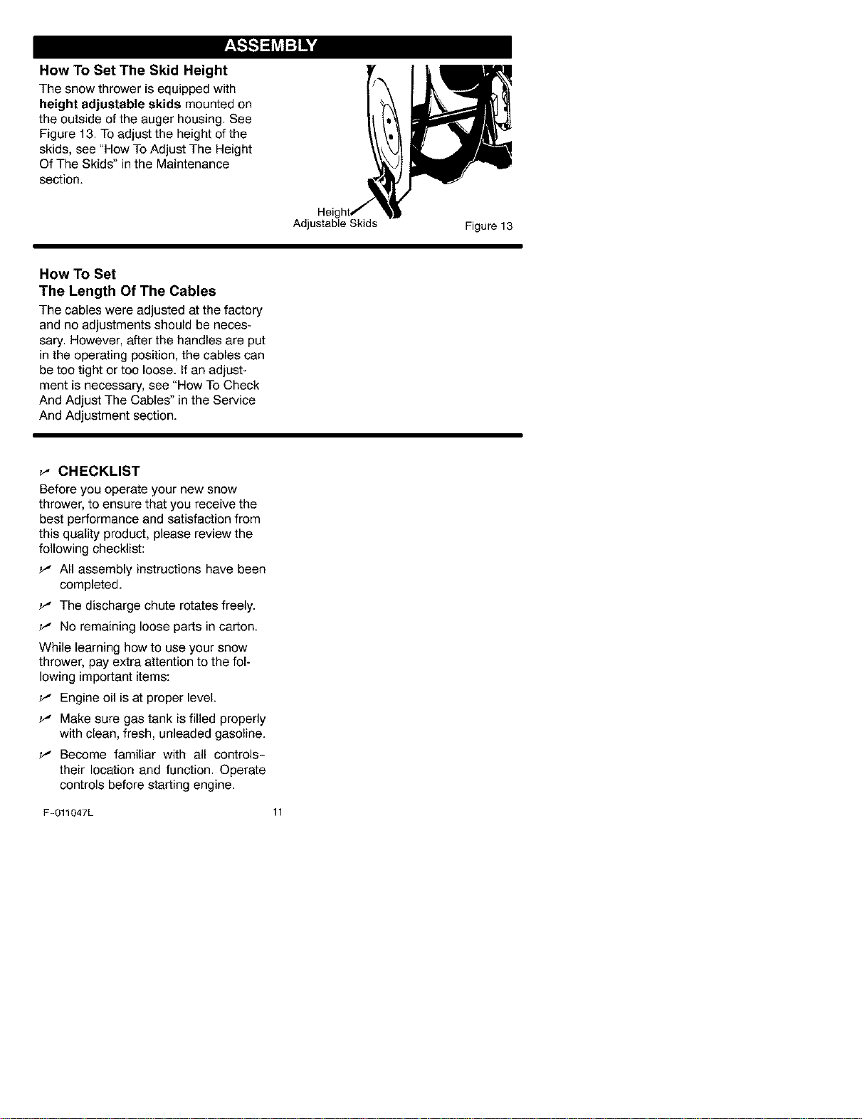
How To Set The Skid Height
The snow thrower is equipped with
height adjustable skids mounted on
the outside of the auger housing. See
Figure 13. To adjust the height of the
skids, see "How To Adjust The Height
Of The Skids" in the Maintenance
section.
Adjustable Skids
Figure 13
How To Set
The Length Of The Cables
The cables were adjusted at the factory
and no adjustments should be neces-
sary. However, after the handles are put
in the operating position, the cables can
be too tight or too loose. If an adjust-
ment is necessary, see "How To Check
And Adjust The Cables" in the Service
And Adjustment section.
_" CHECKLIST
Before you operate your new snow
thrower, to ensure that you receive the
best performance and satisfaction from
this quality product, please review the
following checklist:
_' All assembly instructions have been
completed.
v' The discharge chute rotates freely.
v" No remaining loose parts in carton.
While learning how to use your snow
thrower, pay extra attention to the fol-
lowingimportant items:
_' Engine oil is at proper level.
v' Make sure gas tank is filled properly
with clean, fresh, unleaded gasoline.
v' Become familiar with all controls-
their location and function. Operate
controls before starting engine.
F-011047L 11
[o]-.l_1:_±'1/ [o]_
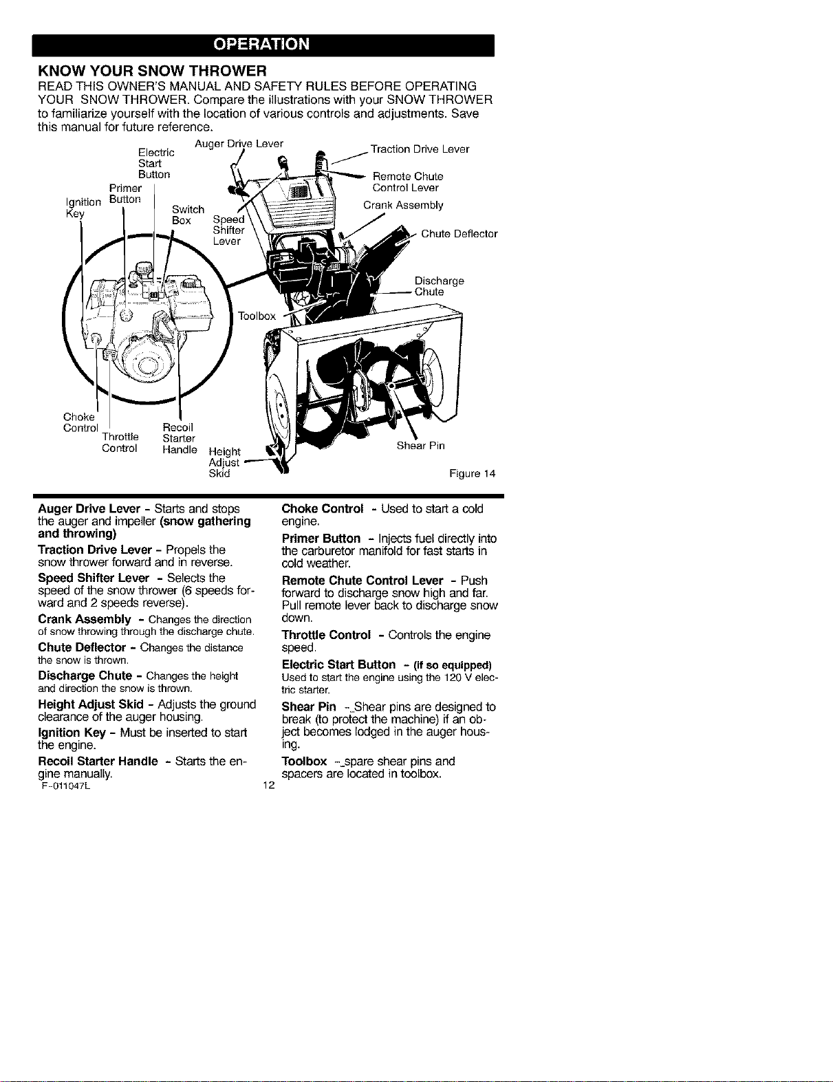
KNOW YOUR SNOW THROWER
READ THIS OWNER'S MANUAL AND SAFETY RULES BEFORE OPERATING
YOUR SNOW THROWER. Compare the illustrations with your SNOW THROWER
to familiarize yourself with the location of various controls and adjustments. Save
this manual for future reference.
Auger Drive Lever Traction Drive Lever
Electric
Start
Button Remote Chute
Primer Control Lever
Ignition Button
Switch Crank Assembly
Key Box
Chute Deflector
Discharge
Choke
Control Recoil
Throttle Starter
Control Handle Height
Skid
Shear Pin
Figure 14
Auger Drive Lever - Starts and stops
the auger and impeller (snow gathering
and throwing)
Traction Drive Lever - Propels the
snow thrower forward and in reverse.
Speed Shifter Lever - Selects the
speed of the snow thrower (6 speeds for-
ward and 2 speeds reverse).
Crank Assembly - Changesthe direction
of snowthrowingthroughthe dischargechute.
Chute Deflector - Changes the distance
the snow isthrown.
Discharge Chute - Changesthe heigl_
anddirectionthe snow isthrown.
Height Adjust Skid - Adjusts the ground
clearance of the auger housing.
Ignition Key - Must be inserted to start
the engine.
Recoil Starter Handle - Starts the en-
gine manually.
F-011047L
12
Choke Control - Used to start a cold
engine.
Primer Button - Injects fuel directly into
the carburetor manifold for fast starts in
cold weather.
Remote Chute Control Lever - Push
forward to discharge snow high and far.
Pull remote lever back to discharge snow
down.
Throttle Control - Controls the engine
speed.
Electric Start Button - (if so equipped)
Usedto startthe engine usingthe 120V elec-
tnc starter.
Shear Pin -=Shear pins are designed to
break (to protect the machine) ff an ob-
iect becomes lodged in the auger hous-
ing.
Toolbox -spare shear pins and
spacers are located in toolbox.
[o]-.l_1:_±'1/ [o]_
The operation of any snow thrower can
result in foreign objects being thrown
into the eyes, which can result in se-
vere eye damage. Always wear safety
glasses or eye shields while operating
the snow thrower.
We recommend standard safety
glasses or a wide vision safety mask for
over your glasses.
_ ARNING: Read Owner's
Manual before operating
machine. Never direct dis-
charge toward bystanders. Stop the
engine before unclogging discharge
chute or auger housing and before
leaving the machine.
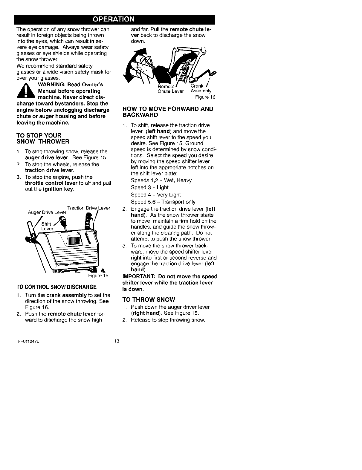
TO STOP YOUR
SNOW THROWER
1. To stop throwing snow, release the
auger drive lever. See Figure 15.
2. To stop the wheels, release the
traction drive lever.
3. To stop the engine, push the
throttle control lever to off and pull
out the ignition key.
Traction Drive Lever
Figure 15
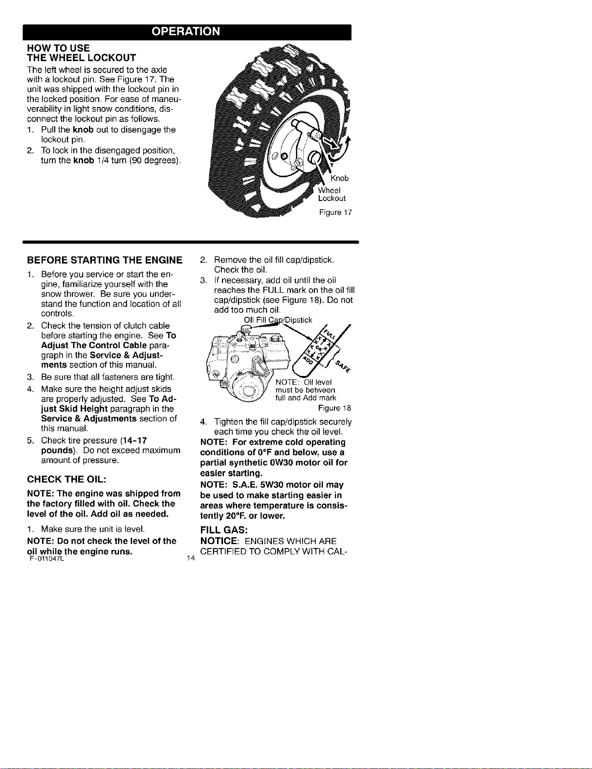
TOCONTROLSNOWDISCHARGE
1. Turn the crank assembly to set the
direction of the snow throwing. See
Figure 16.
2. Push the remote chute lever for-
ward to discharge the snow high
and far. Pull the remote chute le-
ver back to discharge the snow
down.
Chute Lever Assembly
Figure 16
HOW TO MOVE FORWARD AND
BACKWARD
1. TO shift, release the traction drive
lever (left hand) and move the
speed shift lever to the speed you
desire. See Figure 15. Ground
speed is determined by snow condi-
tions. Select the speed you desire
by moving the speed shifter lever
left into the appropriate notches on
the shift lever plate:
Speeds 1,2 - Wet, Heaw
Speed 3 - Light
Speed 4 - Very Light
Speed 5,6 - Transport only
2. Engage the traction drive lever (left
hand). As the snow thrower starts
to move, maintain a firm hold on the
handles, and guide the snow throw-
er along the clearing path. Do not
attempt to push the snow thrower.
3. To move the snow thrower back-
ward, move the speed shifter lever
right into first or second reverse and
engage the traction drive lever (left
hand).
IMPORTANT: Do not move the speed
shifter lever while the traction lever
is down.
TO THROW SNOW
1. Push down the auger driver lever
(right hand). See Figure 15.
2. Release to stop throwing snow.
F-011047L 13
[o]-.l_1:_±'1/ [o]_
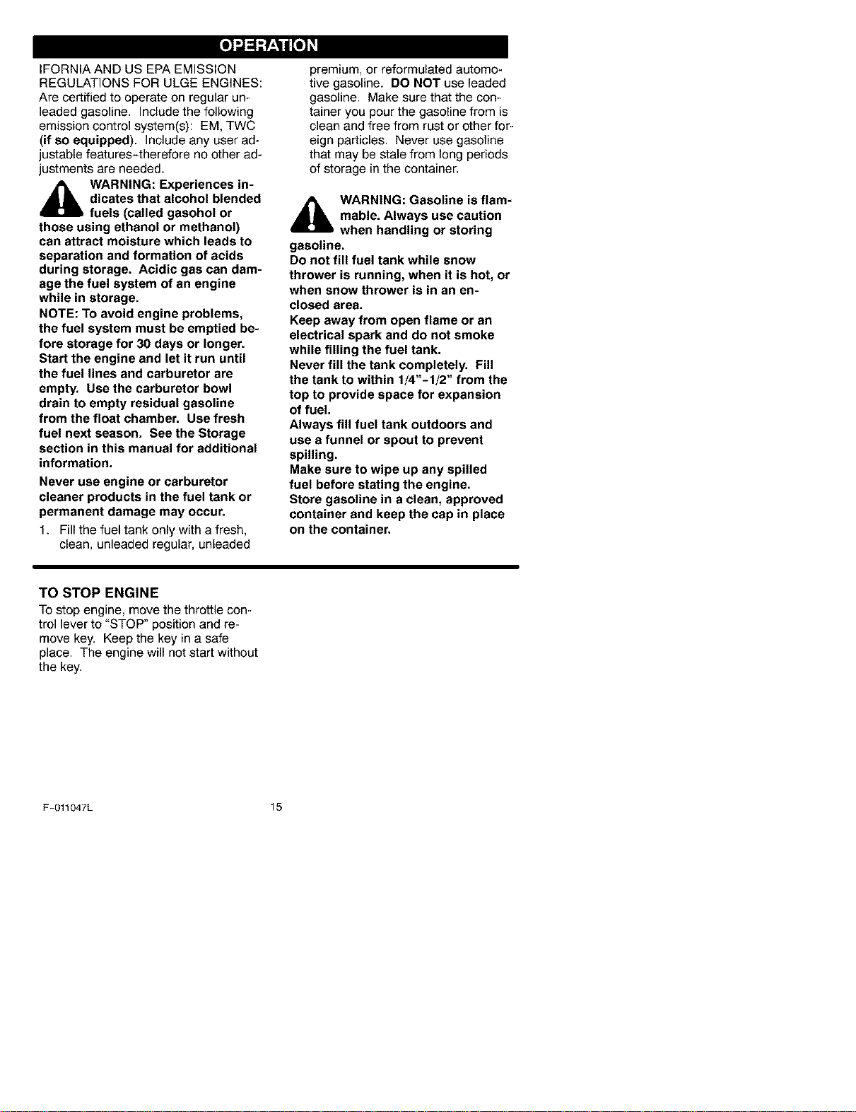
HOW TO USE
THE WHEEL LOCKOUT
The left wheel is secured to the axle
with a lockout pin. See Figure 17. The
unit was shipped with the lockout pin in
the locked position. For ease of maneu-
verability in light snow conditions, dis-
connect the lockout pin as follows.
1. Pull the knob out to disengage the
lockout pin.
2. To lock in the disengaged position,
turn the knob 1/4 turn (90 degrees).
Knob
Wheel
Lockout
Figu_ 17
BEFORE STARTING THE ENGINE
1. Before you service or start the en-
gine, familiarize yourself with the
snow thrower. Be sure you under-
stand the function and location of all
controls.
2. Check the tension of clutch cable
before starting the engine. See To
Adjust The Control Cable para-
graph in the Service & Adjust-
ments section of this manual.
3. Be sure that all fasteners are tight.
4. Make sure the height adjust skids
are properly adjusted. See To Ad-
just Skid Height paragraph in the
Service & Adjustments section of
this manual.
5. Check tire pressure (14-17
pounds). Do not exceed maximum
amount of pressure.
CHECK THE OIL:
NOTE: The engine was shipped from
the factory filled with oil. Check the
level of the oil. Add oil as needed.
1. Make sure the unit is level.
NOTE: Do not check the level of the
oil while the engine runs.
F-011047L
14
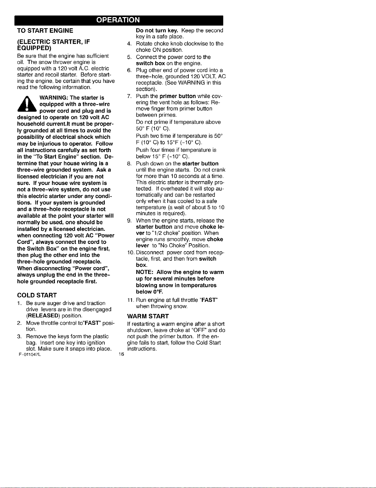
2. Remove the oil fill cap/dipstick.
Check the oil.
3. If necessary, add oil until the oil
reaches the FULL mark on the oil fill
cap/dipstick (see Figure 18). Do not
add too much oil.
_/Dipstick
Figure 18
4. Tighten the fill cap/dipstick securely
each time you check the oil level.
NOTE: For extreme cold operating
conditions of O°F and below, use a
partial synthetic OW3O motor oil for
easier starting.
NOTE: S.A.E. 5W30 motor oil may
be used to make starting easier in
areas where temperature is consis-
tently 2O°F. or lower.
FILL GAS:
NOTICE: ENGINES WHICH ARE
CERTIFIED TO COMPLY WITH CAL-
[o]-.l_1:_±'1/ [o]_
IFORNIA AND US EPA EMISSION
REGULATIONS FOR ULGE ENGINES:
Are certified to operate on regular un-
leaded gasoline. Includethe following
emission control system(s): EM, TWC
(if so equipped). Include any user ad-
justable features-therefore no other ad-
justments are needed.
_[b ARNING: Experiences in-
dicates that alcohol blended
fuels (called gasohol or
those using ethanol or methanol)
can attract moisture which leads to
separation and formation of acids
during storage. Acidic gas can dam-
age the fuel system of an engine
while in storage.
NOTE: To avoid engine problems,
the fuel system must be emptied be-
fore storage for 30 days or longer.
Start the engine and let it run until
the fuel lines and carburetor are
empty, Use the carburetor bowl
drain to empty residual gasoline
from the float chamber. Use fresh
fuel next season, See the Storage
section in this manual for additional
information,
Never use engine or carburetor
cleaner products in the fuel tank or
permanent damage may occur.
1. Fill the fuel tank only with a fresh,
clean, unleaded regular, unleaded
premium, or reformulated automo-
tive gasoline. DO NOT use leaded
gasoline. Make sure that the con-
tainer you pour the gasoline from is
clean and free from rust or other for-
eign particles. Never use gasoline
that may be stale from long periods
of storage in the container.
_lb ARNING: Gasoline is flam-
mable. Always use caution
when handling or storing
gasoline.
Do not fill fuel tank while snow
thrower is running, when it is hot, or
when snow thrower is in an en-
closed area,
Keep away from open flame or an
electrical spark and do not smoke
while filling the fuel tank,
Never fill the tank completely, Fill
the tank to within 1/4"-1/2" from the
top to provide space for expansion
of fuel,
Always fill fuel tank outdoors and
use a funnel or spout to prevent
spilling.
Make sure to wipe up any spilled
fuel before stating the engine,
Store gasoline in a clean, approved
container and keep the cap in place
on the container.
TO STOP ENGINE
To stop engine, move the throttle con-
trol lever to "STOP" position and re-
move key. Keep the key in a safe
place. The engine will not start without
the key.
F-011047L 15
[o]-.l_1:_±'1/ [o]_
TO START ENGINE
(ELECTRIC STARTER, IF
EQUIPPED)
Be sure that the engine has sufficient
oil. The snow thrower engine is
equipped with a 120 volt A.C. electric
starter and recoil starter. Before start-
ing the engine, be certain that you have
read the following information.
_lb WARNING: The starter is
equipped with a three-wire
power cord and plug and is
designed to operate on 120 volt AC
household current.It must be proper-
ly grounded at all times to avoid the
possibility of electrical shock which
may be injurious to operator. Follow
all instructions carefully as set forth
in the "To Start Engine" section. De-
termine that your house wiring is a
three-wire grounded system. Ask a
licensed electrician if you are not
sure. If your house wire system is
not a three-wire system, do not use
this electric starter under any condi-
tions. If your system is grounded
and a three-hole receptacle is not
available at the point your starter will
normally be used, one should be
installed by a licensed electrician.
when connecting 120 volt AC "Power
Cord", always connect the cord to
the Switch Box" on the engine first,
then plug the other end into the
three-hole grounded receptacle.
When disconnecting "Power cord",
always unplug the end in the three-
hole grounded receptacle first.
COLD START
1. Be sure auger drive and traction
drive levers are in the disengaged
(RELEASED) position.
2. Move throttle control to'FAST" posi-
tion.
3. Remove the keys form the plastic
bag. Insert one key into ignition
slot. Make sure it snaps into place.
F-011047L
16
Do not turn key. Keep the second
key in a safe place.
4. Rotate choke knob clockwise to the
choke ON position.
5. Connect the power cord to the
switch box on the engine.
6. Plug other end of power cord into a
three-hole, grounded 120 VOLT, AC
receptacle. (See WARNING in this
section).
7. Push the primer button while cov-
ering the vent hole as follows: Re-
move finger from primer button
between primes.
Do not prime if temperature above
50 ° F (10oC).
Push two time if temperature is 50°
F (10° C) to 15°F (-10 ° C).
Push four times if temperature is
below 15° F (-10 ° C).
8. Push down on the starter button
until the engine starts. Do not crank
for more than 10 seconds at a time.
This electric starter is thermally pro-
tected. If overheated it will stop au-
tomatically and can be restarted
only when it has cooled to a safe
temperature (a wait of about 5 to 10
minutes is required).
9. When the engine starts, release the
starter button and move choke le-
ver to "1/2 choke" position. When
engine runs smoothly, move choke
lever to "No Choke" Position.
10. Disconnect power cord from recep-
tacle, first, and then from switch
box.
NOTE: Allow the engine to warm
up for several minutes before
blowing snow in temperatures
below O°F.
11. Run engine at full throttle "FAST"
when throwing snow.
WARM START
If restarting a warm engine after a short
shutdown, leave choke at "OFF" and do
not push the primer button. If the en-
gine fails to start, follow the Cold Start
instructions.
[o]-.l_1:_±'1/ [o]_
TO START ENGINE
(RECOIL STARTER)
Be sure that the engine has sufficient
oil. The snow thrower engine is
equipped with a recoil starter. Before
starting the engine, be certain that you
have read the following information.
COLD START
1. Be sure auger drive and traction
drive levers are in the disengaged
(RELEASED) position.
2. Move throttle control to"FAST" posi-
tion.
3. Remove the keys form the plastic
bag. Insert one key into ignition
slot. Make sure it snaps into place.
Do not turn key. Keep the second
key in a safe place.
4. Rotate choke knob clockwise to the
choke ON position.
5. Push the primer button while cov-
ering the vent hole as follows: Re-
move finger from primer button
between primes.
Do not prime if temperature above
50° F (10° C).
Push two time if temperature is 50°
F (10° C) to 15°F (-10 ° C).
Push four times if temperature is
below 15° F (-10 ° C).
6. Pull the starter handle rapidly. Do
not allow the handle to snap back,
but allow it to rewind slowly while
keeping a firm hold on the starter
handle.
7. As the engine warms up, move
choke lever to "1/2 choke" position.
When engine runs smoothly, move
choke lever to "No Choke" Posi-
tion.
NOTE: Allow the engine to warm
up for several minutes before
blowing snow in temperatures
below 0°F.
8. Run engine at full throttle "FAST'
when throwing snow.
F-011047L
17
WARM START
If restarting a warm engine after a short
shutdown, leave choke at "OFF" and do
not push the primer button. If the en-
gine fails to start, follow the Cold Start
instructions.
FROZEN STARTER
Ifthe starter is frozen and will not turn
engine:
1. Pull as much rope out of the starter
as possible.
2. Release the starter handle and let it
snap back against the starter.
Ifthe engine still fails to start, repeat the
two previous steps until the engine
starts. Then continue with the direc-
tions for cold start.
To help prevent possible freeze-up of
recoil starter and engine controls, pro-
ceed as follows after each snow remov-
al job.
1. With the engine running, pull the
starter rope hard with a continuous
full arm stroke three or four times.
Pulling of starter rope will produce a
loud clattering sound. This is not
harmful to the engine or starter.
2. With the engine not running, wipe all
snow and moisture from the carbu-
retor cover in area of control levers.
Also move throttle control, choke
control, and starter handle several
times.
d_lb WARNING: Never run en-
gine indoors or in enclosed,
poorly ventilated areas. En-
gine exhaust contains CARBON
MONOXIDE, AN ODORLESS AND
DEADLY GAS. Keep hands, feet,
hair and loose clothing away from
any moving parts on engine and
snow thrower.
The temperature of muffler and
nearby areas may exceed 150°1=.
Avoid these areas.
DO NOT allow children or young
teenagers to operate or be near
snow thrower while it is operating.
[o]-.l_1:_±'1/ [o]_
_hb ARNING: Do not attempt
to remove any item that may
become lodged in auger
without taking the following precau-
tions:
• Release auger drive lever.
• Move throttle lever to stop posi-
tion.
• Remove (do not turn) ignition
key.
• Disconnect spark plug wire.
• Do not place your hands in the
auger or discharge chute. Use a
pry bar.
SNOW THROWING TIPS
1. For maximum snow thrower efficien-
cy in removing snow, adjust ground
speed, NEVER the throttle. Go
slower in deep, freezing or wet
snow. If the wheels slips, reduce
forward speed. The engine is de-
signed to deliver maximum perfor-
mance at full throttle and should be
run at this power setting at all times.
2. Most efficient snow throwing is ac-
complished when the snow is re-
moved immediately after if falls.
3. For complete snow removal, slightly
overlap each path previously taken.
4. The snow should be discharged
down wind whenever possible.
5. For normal usage, set the skids so
that the scraper bar is 1/8" above
the skids. For extremely hard-
packed snow surfaces, adjust the
skids upward so that the scraper
bar touches the ground.
6. On gravel or crushed rock surfaces,
set the skids at 1-1/4" below the
scraper bar. See To Adjust Skid
Height paragraph in the Service &
Adjustments section of this manu-
al. Rocks and gravel must not be
picked up and thrown by the ma-
chine.
7. After the snow throwing job has
been completed, allow the engine to
idle for a few minutes, which will
melt snow and accumulated ice off
the engine.
8. Clean the snow thrower thoroughly
after each use.
9. Remove ice and snow accumulation
and all debris from the entire snow
thrower, and flush with water (if pos-
sible) to remove all salt or other
chemicals. Wipe snow thrower dry.
F-011047L 18
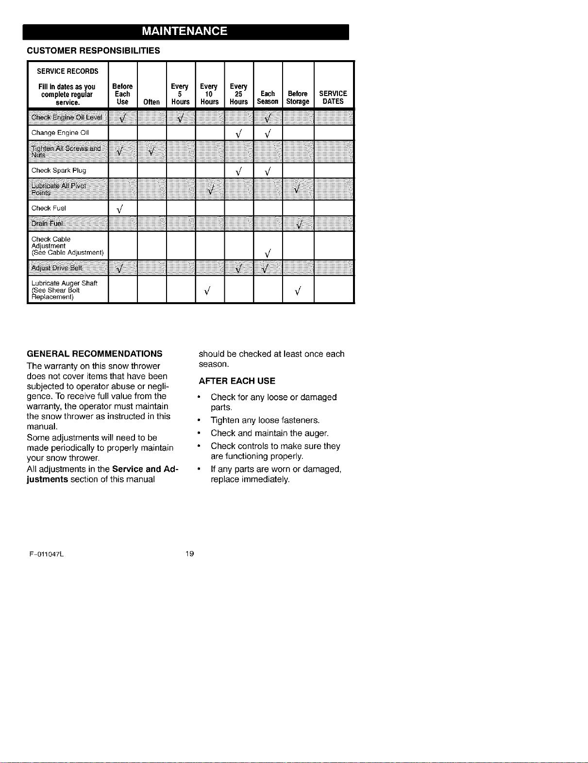
CUSTOMER RESPONSIBILITIES
SERVICERECORDS
Fillindatesasyou Before
completeregular Each
service. Usa Often
Change Engine Oil
_ ...........................::::::::::::::::::::::
Check Spark Plug
Check Fuel _/
Check Cable
Adjustment
See Cable Adjustment)
Lubricate Auger Shaft
See Shear Bolt
Replacement)
Every Every Every
5 10 25 Each Before SERVICE
Hours Hours Hours Season Storage DATES
iiiiiiiiiiiiiiiiiiiiiiiiiiiiiiiiiiiiiiiiiiiiiiiiiiiiiiiiiiiiiii ili!i!;!
,/ ,/
iiiiiiiiiiiiiiiiiiiiiiiiiiiiiiiiiiiiiiiiiiiiiiiiiiiiiiiiiii'ii'ii i ii!!i!
,/ ,/
iiiiiiiiiiiiiiiiiiiiiiiiiiiiiiiiiiiiiiiiiiiiiiiiiiiiiiiiiii'ii'ii i ii !i!
,/
,/
,/
iiiiiiiiiiiiiiiiiiiiiiiiiiiiiiiiiiiiiiiiiiiiiiiiiiiiiiiiiiiiiij i i!i!;!
GENERAL RECOMMENDATIONS
The warranty on this snow thrower
does not cover items that have been
subjected to operator abuse or negli-
gence. To receive full value from the
warranty, the operator must maintain
the snow thrower as instructed in this
manual.
Some adjustments will need to be
made periodically to properly maintain
your snow thrower.
All adjustments in the Service and Ad-
justments section of this manual
should be checked atleast once each
season.
AFTER EACH USE
Check for any loose or damaged
parts.
Tighten any loose fasteners.
Check and maintain the auger.
Check controls to make sure they
are functioning properly.
If any parts are worn or damaged,
replace immediately.
F-011047L 19
PRODUCT SPECIFICATIONS
HORSEPOWER 11 HP
DISPLACEMENT 21.82 cu, in.
GASOLINE 4 quarts
CAPACITY (unleaded)
OIL CAPACITY 5W30
(20 oz capacity)
SPARK PLUG: Champion RJt 9LM
(Gap ,030 in.) or
equivalent
VALVE CLEARANCE: Intake: ,010 In,
Exhaust: ,010 In,
SNOW THROWER
AS REQUIRED
The following adjustment should be
preformed more than once each sea-
son.
1. Auger drive belt should be adjusted
after the first 2 to 4 hours of use,
again about mid-season and twice
each season thereafter (See to Ad-
just Belts paragraph in the Ser-
vice and Adjustment section).
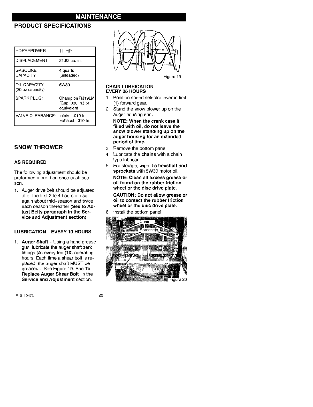
LUBRICATION - EVERY 10 HOURS
1. Auger Shaft - Using a hand grease
gun, lubricate the auger shaft zerk
fittings (A) every ten (10) operating
hours. Each time a shear bolt is re-
placed, the auger shaft MUST be
greased. See Figure 19. See To
Replace Auger Shear Bolt in the
Service and Adjustment section.
Figure 19
CHAIN LUBRICATION
EVERY 25 HOURS
1. Position speed selector lever in first
(1) forward gear.
2. Stand the snow blower up on the
auger housing end.
NOTE: When the crank case if
filled with oil, do not leave the
snow blower standing up on the
auger housing for an extended
period of time.
3. Remove the bottom panel.
4. Lubricate the chains with a chain
type lubricant.
5. For storage, wipe the hexshaft and
sprockets with 5W30 motor oil.
NOTE: Clean all excess grease or
oil found on the rubber friction
wheel or the disc drive plate.
CAUTION: Do not allow grease or
oil to contact the rubber friction
wheel or the disc drive plate.
6. Install the bottom panel.
Figure 20
F-011047L 20
AUGER GEAR BOX
The auger gear box is lubricated at the
factory and should not require addition-
al lubrication. Iffor some reason the
lubricant should leak out, have auger
gear case checked by a competent re-
pairman.
ENGINE
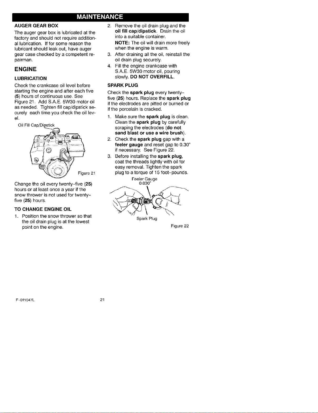
LUBRICATION
Check the crankcase oil level before
starting the engine and after each five
(5) hours of continuous use. See
Figure 21. Add S.A.E. 5W30 motor oil
as needed. Tighten fill cap/dipstick se-
curely each time you check the oil lev-
el.
Oil Fill Cap/Dipstick
Figure 21
Change the oil every twenty-five (25)
hours or at least once a year if the
snow thrower is not used for twenty-
five (25) hours.
TO CHANGE ENGINE OIL
1. Position the snow thrower so that
the oil drain plug is at the lowest
point on the engine.
2. Remove the oil drain plug and the
oil fill cap/dipstick. Drain the oil
into a suitable container.
NOTE: The oil will drain more freely
when the engine is warm.
3. After draining all the oil, reinstall the
oil drain plug securely.
4. Fill the engine crankcase with
S.A.E. 5W30 motor oil, pouring
slowly. DO NOT OVERFILL.
SPARK PLUG
Check the spark plug every twenty-
five (25) hours. Replace the spark plug
if the electrodes are pitted or burned or
if the porcelain is cracked.
1. Make sure the spark plug is clean.
Clean the spark plug by carefully
scraping the electrodes (do not
sand blast or use a wire brush).
2. Check the spark plug gap with a
feeler gauge and reset gap to 0.30"
if necessary. See Figure 22.
3. Before installing the spark plug,
coat the threads lightly with oil for
easy removal. Tighten the spark
plug to a torque of 15 foot-pounds.
Feeler Gauge
0.030"
Spark Plug
Figure 22
F-011047L 21
_lb ARNING: Always discon-
nect the spark plug wire and
place it where it cannot
make contact with spark plug to pre-
vent accidental starting when mak-
ing any adjustments or repairs.
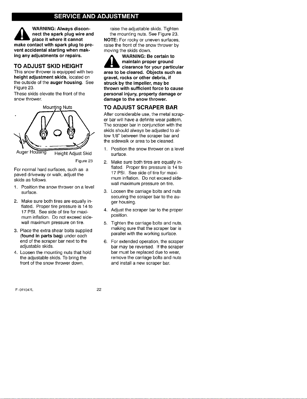
TO ADJUST SKID HEIGHT
This snow thrower is equipped with two
height adjustment skids, located on
the outside of the auger housing. See
Figure 23.
These skids elevate the front of the
snow thrower.
Nuts
O
Auger F
Height Adjust Skid
Figure23
For normal hard surfaces, such as a
paved driveway or walk, adjust the
skids as follows.
1. Position the snow thrower on a level
surface.
2. Make sure both tires are equally in-
flated. Proper tire pressure is 14to
17 PSI. See side of tire for maxi-
mum inflation. Do not exceed side-
wall maximum pressure on tire.
3. Place the extra shear bolts supplied
(found in parts bag) under each
end of the scraper bar next to the
adjustable skids.
4. Loosen the mounting nuts that hold
the adjustable skids. To bring the
front of the snow thrower down,
raise the adjustable skids. Tighten
the mounting nuts. See Figure 23.
NOTE: For rocky or uneven surfaces,
raise the front of the snow thrower by
moving the skids down.
_ WARNING: Be certain to
maintain proper ground
clearance for your particular
area to be cleared. Objects such as
gravel, rocks or other debris, if
struck by the impeller, may be
thrown with sufficient force to cause
personal injury, property damage or
damage to the snow thrower.
TO ADJUST SCRAPER BAR
After considerable use, the metal scrap-
er bar will have a definite wear pattern.
The scraper bar in conjunction with the
skids should always be adjusted to al-
low 1/8" between the scraper bar and
the sidewalk or area to be cleaned.
1. Position the snow thrower on a level
surface.
2,
3,
4.
5.
6.
Make sure both tires are equally in-
flated. Proper tire pressure is 14to
17 PSI. See side of tire for maxi-
mum inflation. Do not exceed side-
wall maximum pressure on tire.
Loosen the carriage bolts and nuts
securing the scraper bar to the au-
ger housing.
Adjust the scraper bar to the proper
position.
Tighten the carriage bolts and nuts,
making sure that the scraper bar is
parallel with the working surface.
For extended operation, the scraper
bar may be reversed. If the scraper
bar must be replaced due to wear,
remove the carriage bolts and nuts
and install a new scraper bar.
F-011047L 22
BELT ADJUSTMENT
Traction Drive Belt
The traction drive belt has constant
spring pressure and does not require
an adjustment. If the traction drive belt
is slipping, replace the belt. See "How
To Replace The Belts" in the Mainte-
nance section.
Auger Drive Belt
Ifyour snow blower will not discharge
snow, check the control cable adjust-
ment. If it is correct, then check the
condition of the auger drive belt. If it is
damaged or loose, replace it (see Belt
Replacement in this section of the
manual).
1. Disconnect spark plug wire.
2. Remove screw from belt cover,
Remove belt cover (see Figure 24).
Figure 24
3. Loosen nut on auger idler pulley
and move auger idler pulley towards
belt about 1/8 inch (3 ram) (see
Figure 27).
4. Tighten nut.
F-011047L
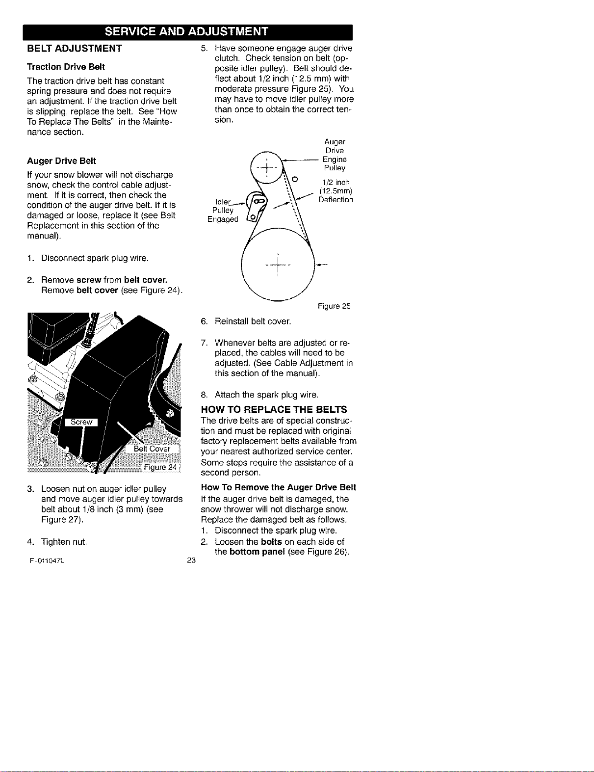
5. Have someone engage auger drive
clutch. Check tension on belt (op-
posite idler pulley). Belt should de-
flect about 1/2 inch (12.5 mm) with
moderate pressure Figure 25). You
may have to move idler pulley more
than once to obtain the correct ten-
sion.
Auger
Drive
l "_-- Engine
--_ _ Pulley
J i_ O 1/2 inch
,._ \_.j (12.5mm)
Idler_,.._('/_ /', _-"_ Deflection
P°"°Y1o, "
Engaged ___
Figure25
6. Reinstall belt cover.
7. Whenever belts are adjusted or re-
placed, the cables will need to be
adjusted. (See Cable Adjustment in
this section of the manual).
23
8. Attach the spark plug wire.
HOW TO REPLACE THE BELTS
The drive belts are of special construc-
tion and must be replaced with original
factory replacement belts available from
your nearest authorized service center.
Some steps require the assistance of a
second person.
How To Remove the Auger Drive Belt
Ifthe auger drive belt is damaged, the
snow thrower will not discharge snow.
Replace the damaged belt as follows.
1. Disconnect the spark plug wire.
2. Loosen the bolts on each side of
the bottom panel (see Figure 26).
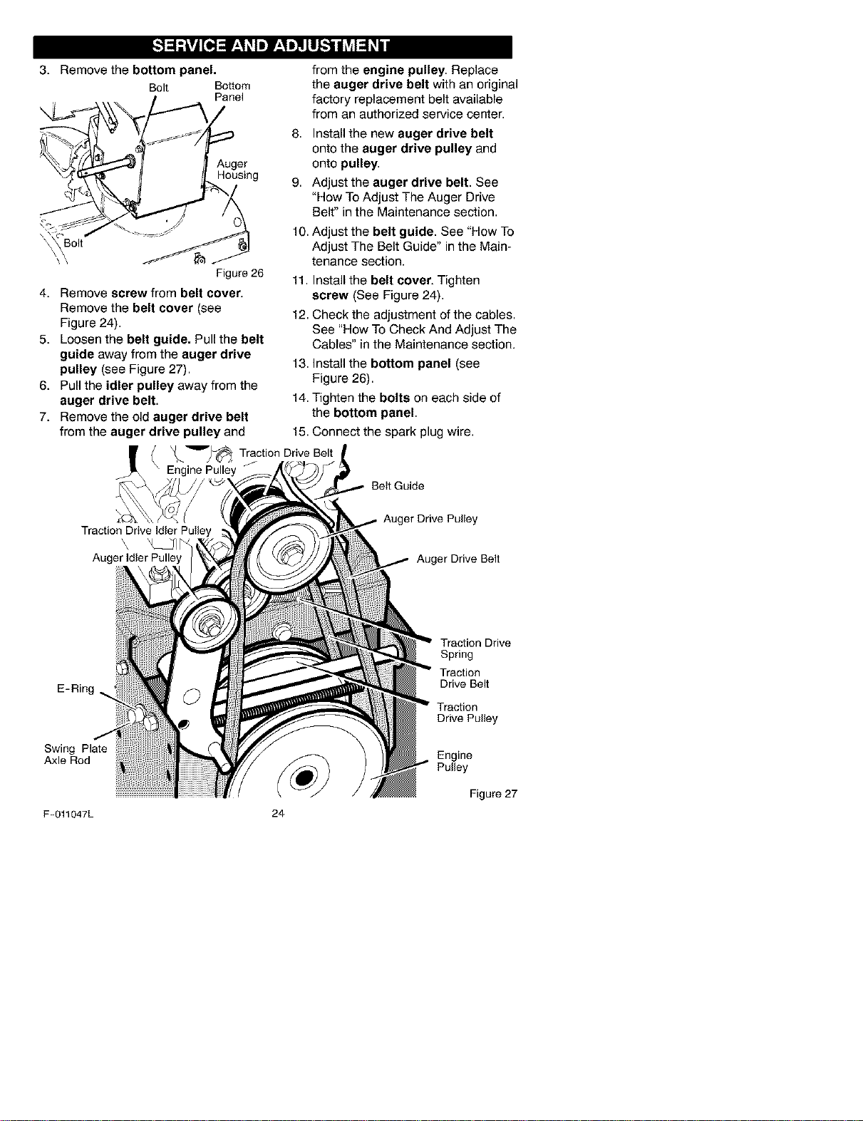
3. Remove the bottom panel.
Bolt Bottom
Panel
from the engine pulley. Replace
the auger drive belt with an original
factory replacement belt available
from an authorized service center.
Auger
Housing
8. Install the new auger drive belt
onto the auger drive pulley and
onto pulley.
9. Adjust the auger drive belt. See
"How To Adjust The Auger Drive
Belt" in the Maintenance section.
Figure 26
4. Remove screw from belt cover.
Remove the belt cover (see
Figure 24).
5. Loosen the belt guide. Pull the belt
guide away from the auger drive
pulley (see Figure 27).
6. Pull the idler pulley away from the
auger drive belt.
7. Remove the old auger drive belt
10. Adjust the belt guide. See "How To
Adjust The Belt Guide" in the Main-
tenance section.
11. Install the belt cover. Tighten
screw (See Figure 24).
12. Check the adjustment of the cables.
See "How To Check And Adjust The
Cables" in the Maintenance section.
13. Install the bottom panel (see
Figure 26).
14. Tighten the bolts on each side of
the bottom panel.
from the auger drive pulley and 15. Connect the spark plug wire.
X__'_'_ Traction Drive Belt
Engine Pulley
Beit Guide
Auger Drive Pulley
'\ _CJl/_
Auger Idler Pulley Auger Drive Belt
E-Ring
Swing Plate
Axle Rod
Traction Drive
Spring
Traction
Drive Belt
Traction
Drive Pulley
Engine
Pulley
Figure 27
F-011047L 24
How To Remove
The Traction Drive Belt
Ifthe snow thrower will not move for-
ward, check the traction drive belt for
wear or damage. If the traction drive
belt is worn or damaged, replace the
belt as follows.
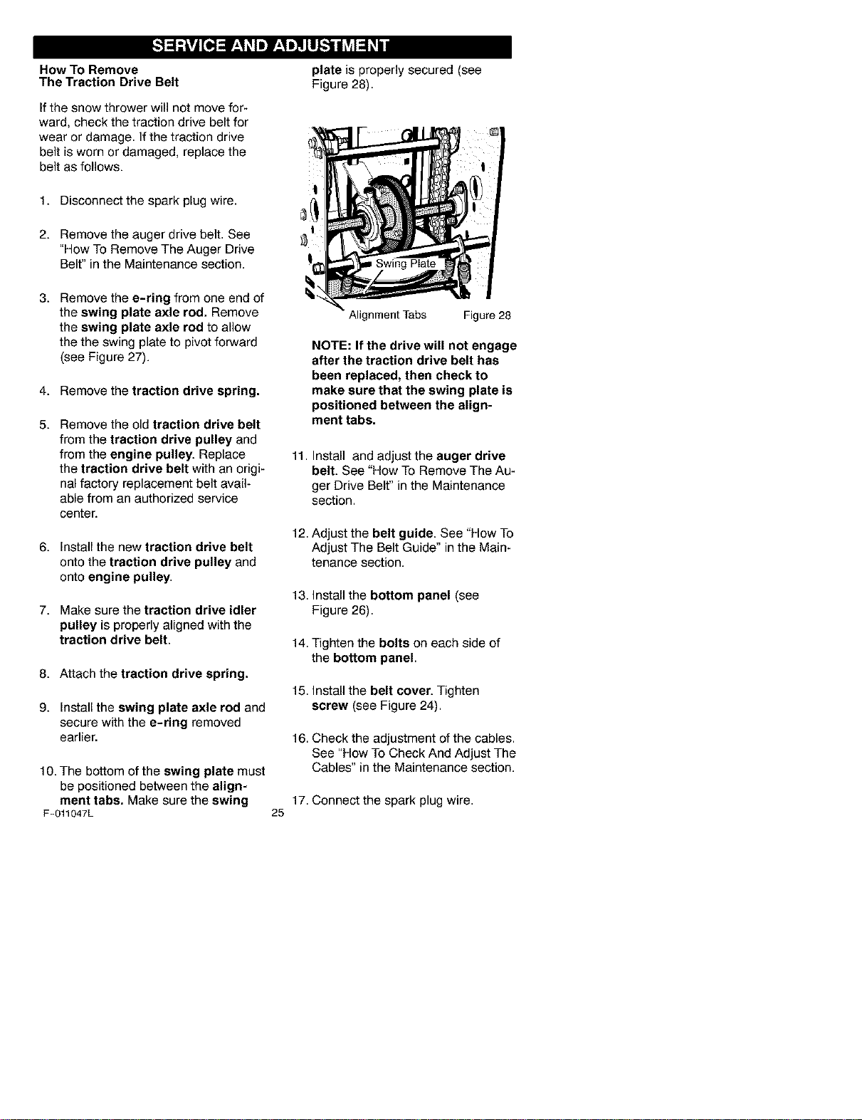
plate is properly secured (see
Figure 28).
1. Disconnect the spark plug wire.
2. Remove the auger drive belt. See
"How To Remove The Auger Drive
Belt" in the Maintenance section.
I
3. Remove the e-ring from one end of
the swing plate axle rod. Remove
the swing plate axle rod to allow
the the swing plate to pivot forward
(see Figure 27).
4. Remove the traction drive spring.
5. Remove the old traction drive belt
from the traction drive pulley and
from the engine pulley. Replace
the traction drive belt with an origi-
nal factory replacement belt avail-
able from an authorized service
center.
6. Install the new traction drive belt
onto the traction drive pulley and
onto engine pulley.
7. Make sure the traction drive idler
pulley is properly aligned with the
traction drive belt.
8. Attach the traction drive spring.
9. Install the swing plate axle rod and
secure with the e-ring removed
earlier.
10. The bottom of the swing plate must
be positioned between the align-
ment tabs. Make sure the swing
F-011047L
Alignment Tabs Figure 28
NOTE: If the drive will not engage
after the traction drive belt has
been replaced, then check to
make sure that the swing plate is
positioned between the align-
ment tabs.
25
11.
Install and adjust the auger drive
belt. See "How To Remove The Au-
ger Drive Belt" in the Maintenance
section.
12. Adjust the belt guide. See "How To
Adjust The Belt Guide" in the Main-
tenance section.
13.Installthe bottom panel (see
Figure26).
14. Tighten the bolts on each side of
the bottom panel.
15. Install the belt cover. Tighten
screw (see Figure 24).
16. Check the adjustment of the cables.
See "How To Check And Adjust The
Cables" in the Maintenance section.
17. Connect the spark plug wire.
BELT GUIDE ADJUSTMENT
1. Remove spark plug wire.
2. Have someone engage auger drive.
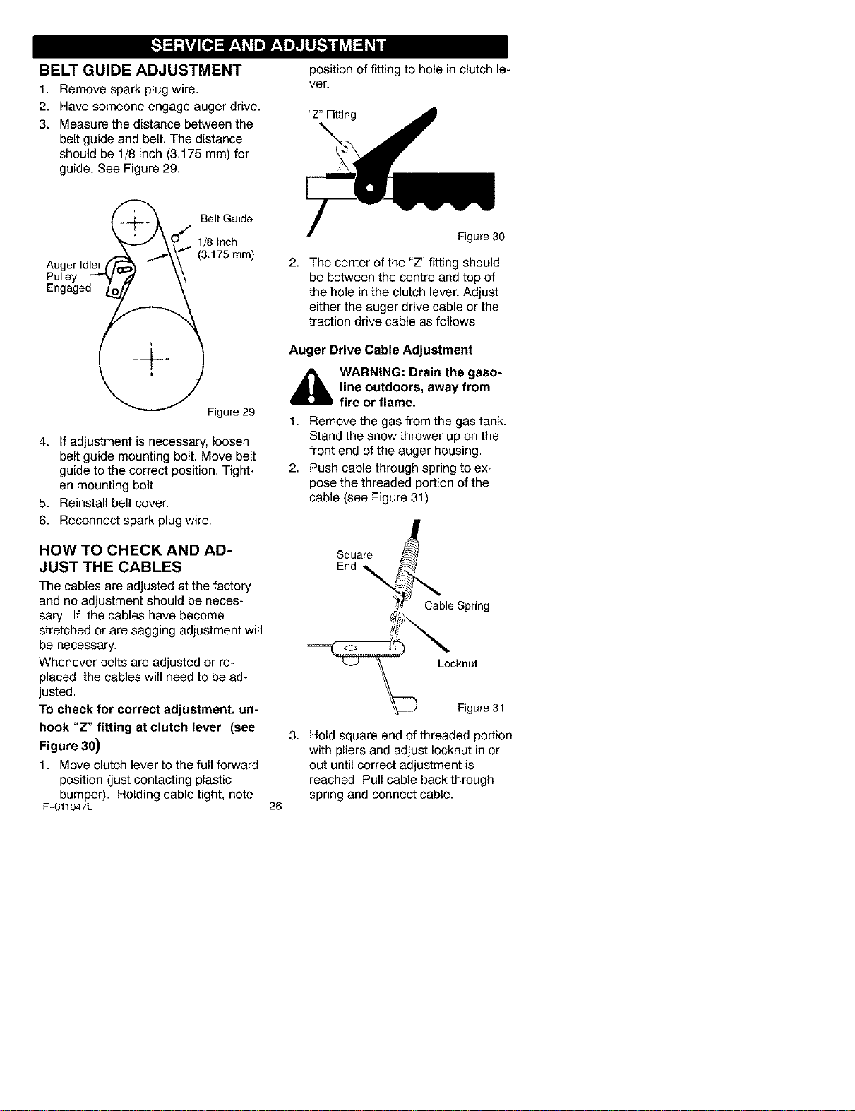
3. Measure the distance between the
belt guide and belt. The distance
should be 1/8 inch (3.175 ram) for
guide. See Figure 29.
position of fitting to hole in clutch le-
ver.
"Z" Fitting
Auger Idler
Pulley
Engaged
Belt Guide
1/8 Inch
(3.175 ram)
Figure29
4. If adjustment is necessary, loosen
belt guide mounting bolt. Move belt
guide to the correct position. Tight-
en mounting bolt.
5. Reinstall belt cover.
6. Reconnect spark plug wire.
HOW TO CHECK AND AD-
JUST THE CABLES
The cables are adjusted at the factory
and no adjustment should be neces-
sary. If the cables have become
stretched or are sagging adjustment will
be necessary.
Whenever belts are adjusted or re-
placed, the cables will need to be ad-
justed.
To check for correct adjustment, un-
hook "Z" fitting at clutch lever (see
Figure 30)
1. Move clutch lever to the full forward
position (just contacting plastic
bumper). Holding cable tight, note
F-011047L
Figure 30
2. The center of the "Z" fitting should
be between the centre and top of
the hole in the clutch lever. Adjust
either the auger drive cable or the
traction drive cable as follows.
Auger Drive Cable Adjustment
_ ARNING: Drain the gaso-
line outdoors, away from
fire or flame.
1. Remove the gas from the gas tank.
Stand the snow thrower up on the
front end of the auger housing.
2. Push cable through spring to ex-
pose the threaded portion of the
cable (see Figure 31).
Square
End
Cable Spring
Locknut
Figure 31
26
3. Hold square end of threaded portion
with pliers and adjust Iocknut in or
out until correct adjustment is
reached. Pull cable back through
spring and connect cable.
TRACTION DRIVE CABLE ADJUSTMENT
_lb WARNING: Drainthe gaso- 5. Pushthe bottomofthetraction
line outdoors, away from
fire or flame, justment bracket untilthe"Z"
1. Remove the gas from the gas tank.
Stand the snow thrower up on the
front end of the auger housing.
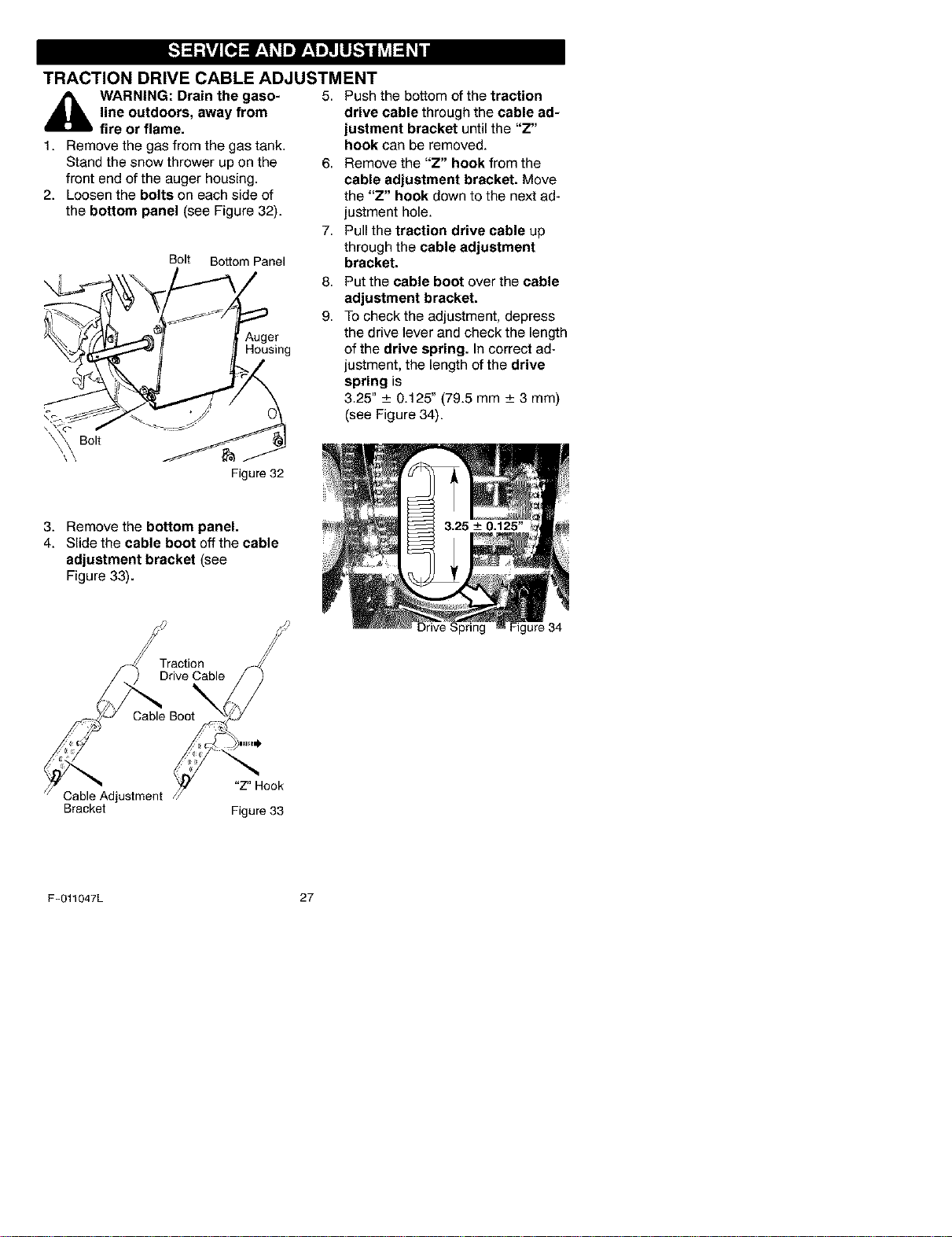
2. Loosen the bolts on each side of
the bottom panel (see Figure 32).
Bolt Bottom Panel
Auger
Housing
\ \ Bolt _/._J
Figure32
drive cable through the cable ad-
hook can be removed.
6. Remove the "Z" hook from the
cable adjustment bracket. Move
the "Z" hook down to the next ad-
justment hole.
7. Pull the traction drive cable up
through the cable adjustment
bracket.
8. Put the cable boot over the cable
adjustment bracket.
9. To check the adjustment, depress
the drive lever and check the length
of the drive spring. In correct ad-
justment, the length of the drive
spring is
3.25" _+0.125" (79.5 mm _+3 mm)
(see Figure 34).
3. Remove the bottom panel.
4. Slide the cable boot off the cable
adjustment bracket (see
Figure 33).
Cable Boo
i 9'""")
?
Cable Adjustment /_I "Z" Hook
Bracket Figure33
Drive Spring Figure 34
F-011047L 27
HOW TO ADJUST OR REPLACE
THE FRICTION WHEEL
How To Check The Friction Wheel
Ifthe snow thrower will not move for-
ward, check the traction drive belt, the
traction drive cable or the friction wheel.
Ifthe friction wheel is worn or damaged,
it must be replaced. See "How To Re-
place the Friction Wheel" in this section.
Ifthe friction wheel is not worn or dam-
aged, check as follows.
1. Remove the gas from the gas tank.
Stand the snow thrower up on the
front end of the auger housing
(see Figure 35).
,_ WARNING: Drain the gaso-
line outdoors, away from
fire or flame.
2. Disconnect the spark plug wire.
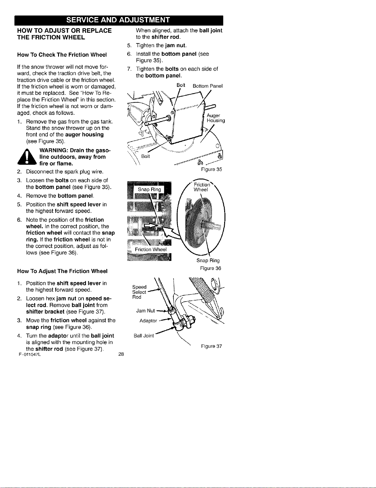
3. Loosen the bolts on each side of
the bottom panel (see Figure 35).
4. Remove the bottom panel.
5. Position the shift speed lever in
the highest forward speed.
6. Note the position of the friction
wheel. In the correct position, the
friction wheel will contact the snap
ring. If the friction wheel is not in
the correct position, adjust as fol-
lows (see Figure 36).
How To Adjust The Friction Wheel
1. Position the shift speed lever in
the highest forward speed.
2. Loosen hex jam nut on speed se-
lect rod. Remove ball joint from
shifter bracket (see Figure 37).
3. Move the friction wheel against the
snap ring (see Figure 36).
4. Turn the adaptor until the ball joint
is aligned with the mounting hole in
the shifter rod (see Figure 37).
F-O11047L
When aligned, attach the ball joint
to the shifter rod.
5. Tighten the jam nut.
6. Install the bottom panel (see
Figure 35).
7. Tighten the bolts on each side of
the bottom panel.
Bolt Bottom Panel
Auger
Housing
Snap Ring
Figure35
28
BallJoint /
\
Snap Ring
Figure 36
Figure 37
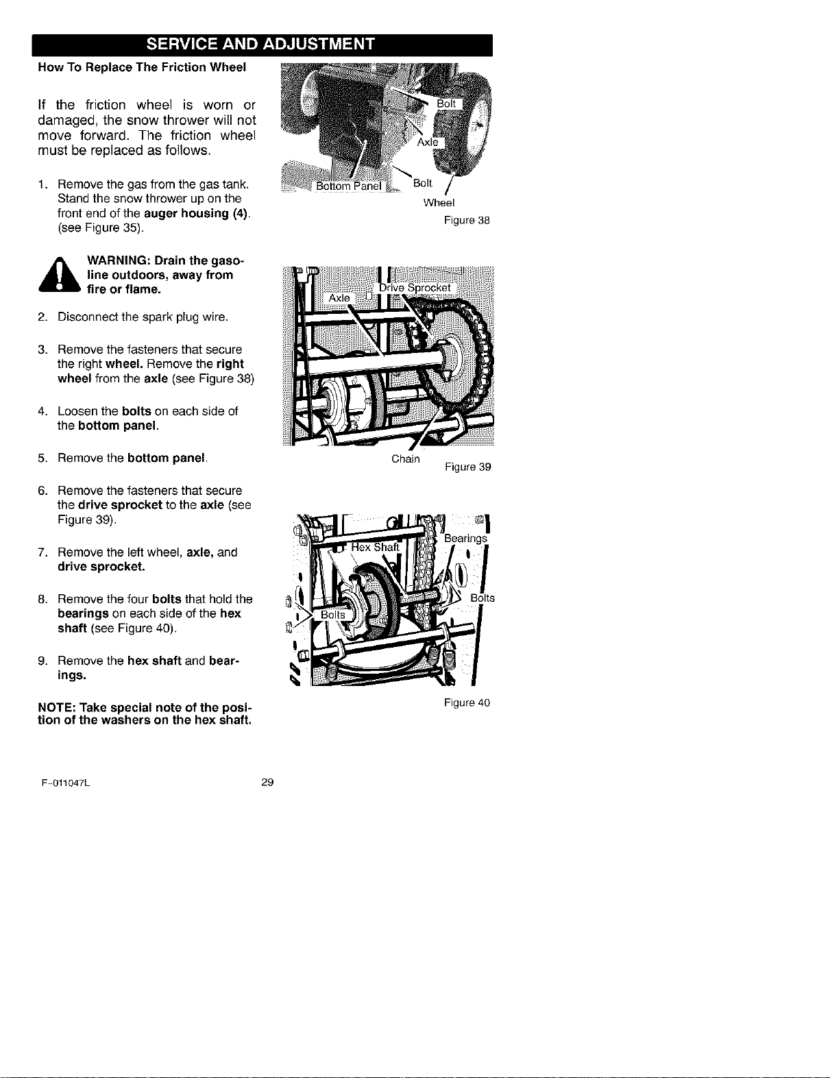
How To Replace The Friction Wheel
If the friction wheel is worn or
damaged, the snow thrower will not
move forward. The friction wheel
must be replaced as follows.
1. Remove the gas from the gas tank.
Stand the snow thrower up on the
front end of the auger housing (4).
(see Figure 35).
_hb ARNING: Drain the gaso-
line outdoors, away from
fire or flame.
2. Disconnect the spark plug wire.
3. Remove the fasteners that secure
the right wheel. Remove the right
wheel from the axle (see Figure 38)
4. Loosen the bolts on each side of
the bottom panel.
5. Remove the bottom panel.
6. Remove the fasteners that secure
the drive sprocket to the axle (see
Figure 39).
7. Remove the left wheel, axle, and
drive sprocket.
8. Remove the four bolts that hold the
bearings on each side of the hex
shaft (see Figure 40).
9. Remove the hex shaft and bear-
ings.
NOTE: Take special note of the posi-
tion of the washers on the hex shaft.
Bolt
Chain
Wheel
Figure 38
Figure 39
Bolts
Figure 40
F-011047L 29
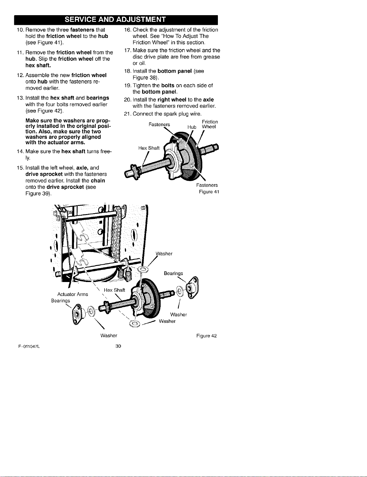
10. Remove the three fasteners that
hold the friction wheel to the hub
(see Figure 41).
11. Remove the friction wheel from the
hub. Slip the friction wheel off the
hex shaft.
12. Assemble the new friction wheel
onto hub with the fasteners re-
moved earlier.
13. Install the hex shaft and bearings
with the four bolts removed earlier
(see Figure 42).
Make sure the washers are prop-
erly installed in the original posi-
tion. Also, make sure the two
washers are properly aligned
with the actuator arms.
14. Make sure the hex shaft turns free-
ly.
15. Install the left wheel, axle, and
drive sprocket with the fasteners
removed earlier. Install the chain
onto the drive sprocket (see
Figure 39).
16. Check the adjustment of the friction
wheel. See "How To Adjust The
Friction Wheel" in this section.
17. Make sure the friction wheel and the
disc drive plate are free from grease
or oil.
18. Install the bottom panel (see
Figure 38).
19. Tighten the bolts on each side of
the bottom panel.
20. Install the right wheel to the axle
with the fasteners removed earlier.
21.
Connect the spark plug wire.
Friction
Fasteners
Hub Wheel
Hex Shaft
Fasteners
Figure 41
Actuator Arms
Bearings
\
Washer
Bearings
1
Washer
Washer
Figure 42
F-O11047L 30
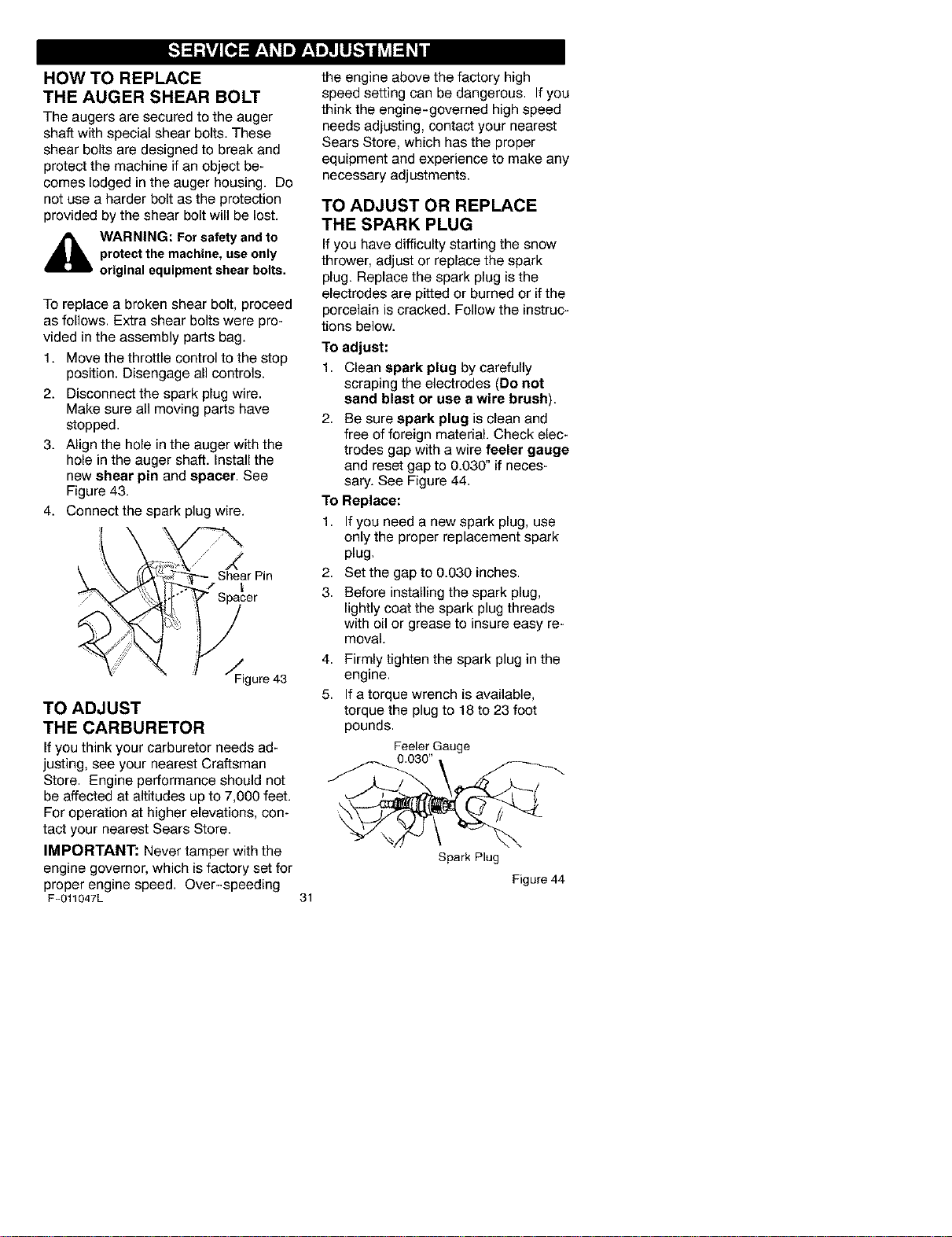
HOW TO REPLACE
THE AUGER SHEAR BOLT
The augers are secured to the auger
shaft with special shear bolts. These
shear bolts are designed to break and
protect the machine if an object be-
comes lodged in the auger housing. Do
not use a harder bolt as the protection
provided by the shear bolt will be lost.
_hb WARNING: For safety andto
protect the machine, useonly
original equipment shear bolts.
To replace a broken shear bolt, proceed
as follows. Extra shear bolts were pro-
vided in the assembly parts bag.
1. Move the throttle control to the stop
position. Disengage all controls.
2. Disconnect the spark plug wire.
Make sure all moving parts have
stopped.
3. Align the hole in the auger with the
hole in the auger shaft. Install the
new shear pin and spacer. See
Figure 43.
4. Connect the spark plug wire.
/ •
_ She_arPin
Figure43
TO ADJUST
THE CARBURETOR
Ifyou think your carburetor needs ad-
justing, see your nearest Craftsman
Store. Engine performance should not
be affected at altitudes up to 7,000 feet.
For operation at higher elevations, con-
tact your nearest Sears Store.
IMPORTANT: Never tamper with the
engine governor, which is factory set for
proper engine speed. Over-speeding
F-011047L
the engine above the factory high
speed setting can be dangerous. If you
think the engine-governed high speed
needs adjusting, contact your nearest
Sears Store, which has the proper
equipment and experience to make any
necessary adjustments.
TO ADJUST OR REPLACE
THE SPARK PLUG
If you have difficultystarting the snow
thrower, adjust or replacethe spark
plug. Replacethe spark plug isthe
electrodes are pitted or burned or ifthe
porcelainis cracked. Follow the instruc-
tions below.
To adjust:
1. Clean spark plug by carefully
scraping the electrodes (Do not
sand blast or use a wire brush).
2. Be sure spark plug is clean and
free of foreign material. Check elec-
trodes gap with a wire feeler gauge
and reset gap to 0.030" if neces-
sary. See Figure 44.
To Replace:
1. If you need a new spark plug, use
only the proper replacement spark
plug.
2. Set the gap to 0.030 inches.
3. Before installing the spark plug,
lightly coat the spark plug threads
with oil or grease to insure easy re-
moval.
4. Firmly tighten the spark plug in the
engine.
5. If a torque wrench is available,
torque the plug to 18 to 23 foot
pounds.
Feeler Gauge
31
Spark Plug
Figure 44
_lb ARNING: Never store your
snow thrower indoors or in
an enclosed, poorly venti-
lated area. If gasoline remains in the
tank, fumes may reach an open
flame, spark or pilot light from a fur-
nace, water heater, clothes dryer,
cigarette, etc.
NOTE: To prevent engine damage (if
snow thrower is not used for more than
30 days) follow the steps below.
SNOW THROWER
1. Thoroughly clean the snow thrower.
2. Lubricate all lubrication points. See
the Maintenance section.
3. Be sure that all nuts, bolts and
screws are securely fastened. In-
spect all visible moving parts for
damage, breakage and wear. Re-
place if necessary.
4. Touch up all rusted or chipped paint
surfaces; sand lightly before paint-
ing.
5. Cover the bare metal parts of the
blower housing auger and the im-
peller with rust preventative, such
as a spray lubricant.
NOTE: A yearly checkup or tune-up by
a Sears service center is a good way of
ensuring that your snow thrower will
provide maximum performance for the
next season.
ENGINE
_blL ARNING: Drain the gaso-
line outdoors, away from
fire or flame.
Gasoline must be removed or treated to
prevent gum deposits from forming in
the fuel tank, filter, hose, and carburetor
during storage. Also, during storage al-
cohol blended gasoline that uses etha-
nol or methanol (sometimes called
gasohol) attracts water. It acts on the
gasoline to form acids which damage
the engine.
F-011047L
1,
2.
3,
4,
5.
TO remove gasoline, run the engine
until the fuel tank is empty and the
engine stops.
If you do not remove the gasoline,
use fuel stabilizer supplied with unit
or purchase Craftsman Fuel Stabi-
lizer No. 3550. Add fuel stabilizer to
any gasoline left in the tank to mini-
mize gum deposits and acids. If the
fuel tank is almost empty, mix stabi-
lizer with fresh gasoline in a sepa-
rate container and add some to the
fuel tank.
Always follow the instruction on the
stabilizer container. After the stabi-
lizer is added to the fuel tank, run
the engine at least ten minutes to
allow the mixture to reach the car-
buretor.
Change the engine oil.
Lubricate the piston/cylinder area.
First, remove the spark plug and
squirt a few drops of clean engine
oil into the spark plug hole. Next,
cover the spark plug hole with a rag
to absorb oil spray. Then, pull two or
three times on the recoil starter rope
to rotate the engine. Finally, install
the spark plug and attach the spark
plug wire.
32
OTHER
1. If possible, store your snow thrower
indoors and cover it to give protec-
tion from dust and dirt.
2. If the machine must be stored out-
doors, block up the snow thrower to
be sure the entire machine is off the
ground.
3. Cover the snow thrower with a suit-
able protective cover that does not
retain moisture. Do not use plastic.
IMPORTANT: Never cover snow
thrower while engine and exhaust areas
are still warm.
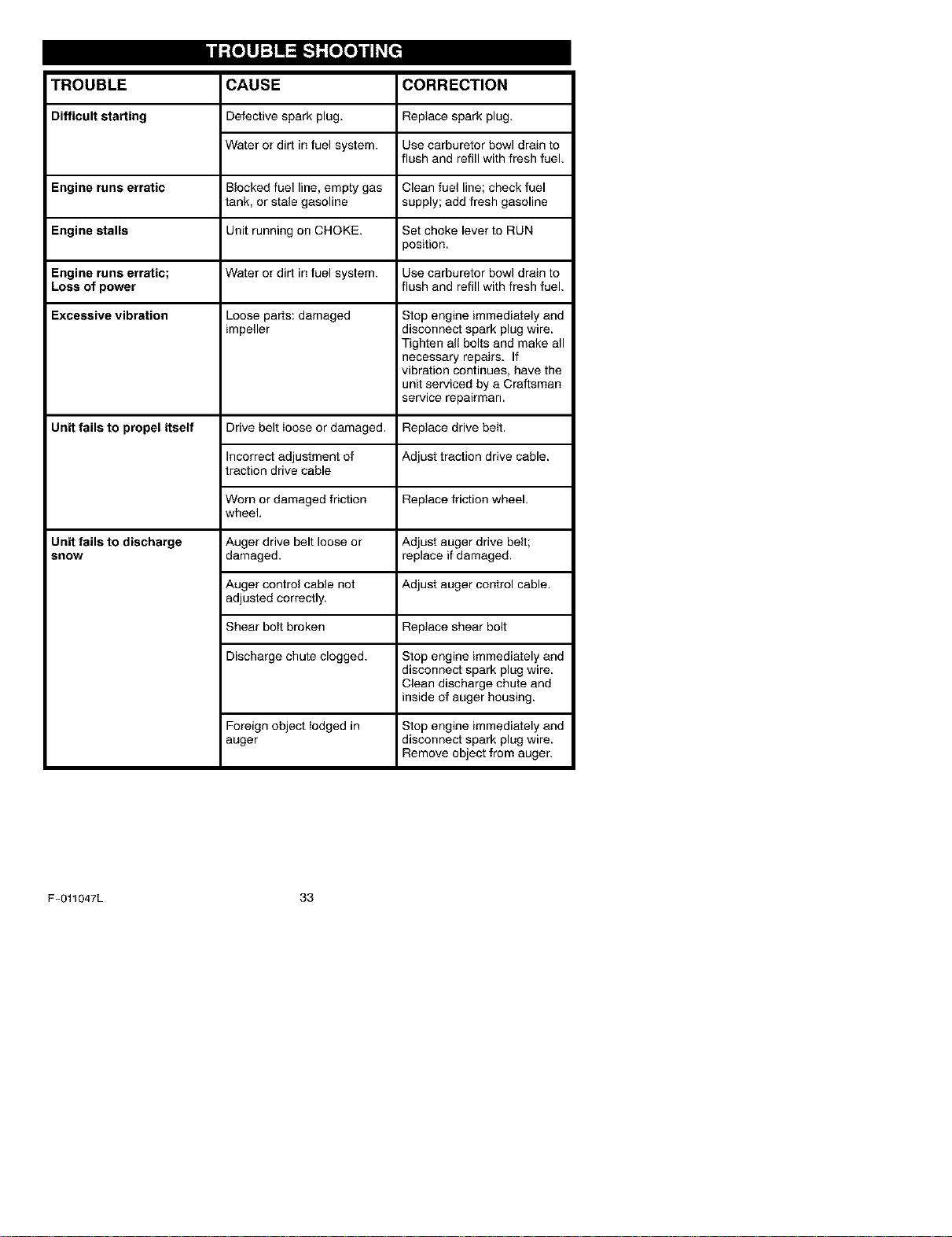
TROUBLE CORRECTION
Difficult starting
CAUSE
Defectivespark plug.
Wateror dirt in fuel system.
Replace spark plug.
Use carburetor bowl drain to
flush and refill with fresh fuel.
Engine runs erratic Blocked fuel line, empty gas Clean fuel line; check fuel
tank, or stale gasoline supply; add fresh gasoline
Engine stalls Unit running on CHOKE. Set choke lever to RUN
position.
Engine runs erratic; Water or dirt in fuel system. Use carburetor bowl drain to
Loss of power flush and refill with fresh fuel.
Excessive vibration Loose parts: damaged Stop engine immediately and
impeller disconnect spark plug wire.
Tighten all bolts and make all
necessary repairs. If
vibration continues, have the
unit serviced by a Craftsman
service repairman.
Unit fails to propel itself Drive belt ioose or damaged.
Incorrect adjustment of
traction drive cable
Worn or damaged friction
wheel,
Auger drive belt loose or
damaged.
Replace drive belt.
Adjust traction drive cable.
Unit fails to discharge
snow
Replace friction wheel.
Adjust auger drive belt;
replace if damaged.
Auger control cable not Adjust auger control cable.
adjusted correctly.
Shear boit broken Replace shear bolt
Discharge chute clogged. Stop engine immediately and
disconnect spark plug wire.
Clean discharge chute and
inside of auger housing.
Foreign object lodged in Stop engine immediately and
auger disconnect spark plug wire.
Remove object from auger.
F-011047L 33
SEARS, ROEBUCK AND CO.
Federal and California Emission Control Systems Limited Warranty
Small Off-Road Engines
CALIFORNIA & US EPA EMISSION
CONTROL WARRANTY STATEMENT
The U. S. Environmental Protection Agency
("EPA"), the California Air Resources Board
("CARB") and Sears, Roebuck and Co. are
pleased to explain the Federal and California
Emission Control Systems Warranty on your
new small oft-road engine. In California, new
1995 and later smali oft-road engines must be
designed, built and equipped to meet the
State's stringent anti-smog standards. In oth-
er states, new 1997 and later model year en-
gines must be designed, built and equipped, at
the time of sale, to meet the U.S. EPA regula-
tions for small non-road engines. Sears, Roe-
buck and Co. will warrant the emission control
system on your small oft-road engine for the
periods of time listed below, provided there
has been no abuse, neglect, unapproved mod-
ification, or improper maintenance of your
small oft-road engine.
Your emission control system may include
parts such as the carburetor, ignition system
and exhaust system. Also included may be the
compression release system and other emis-
sion-related assemblies.
Where a warrantable condition exists, Sears,
Roebuck and Co. will repair your small off-
road engine at no cost to you for diagnosis,
parts and labor.
MANUFACTURER'S EMISSION
CONTROL SYSTEM WARRANTY
COVERAGE
Emission control systems on 1995 and later
model year California small oft-road engines
are warranted for two years as hereinafter
noted. In other states, 1997 and later model
year engines are also warranted for two years.
If, during such warranty period, any emission-
related part on your engine is defective in ma-
terials or workmanship, the part will be
repaired or replaced by Sears, Roebuck and
Co.
OWNER'S WARRANTY
RESPONSIBILITIES
As the small oft-road engine owner, you are
responsible for the performance of the re-
F-011047L
quired maintenance listed in your Owner's
Manual, but Sears, Roebuck and Co. will not
deny warranty solely due to the lack of receipts
or for your failure to provide written evidence
of the performance of all scheduled mainte-
nance.
As the small oft-road engine owner, you
should, however, be aware that Sears, Roe-
buck and Co. may deny you warranty cover-
age if your small oft-road engine or a part
thereof has failed due to abuse, neglect, im-
proper maintenance or unapproved modifica-
tions.
You are responsible for presenting your small
oft-road engine to a Sears, Roebuck and Co.
Authorized Service Outlet as soon as a prob-
lem exists. The warranty repairs should be
completed in a reasonable amount of time, not
to exceed 30 days.
Warranty service can be arranged by contact-
ing either a Sears, Roebuck and Co. Autho-
rized Service Outlet, or by contacting Sears,
Roebuck and Co. at 1-800-473-7247.
34
IMPORTANT NOTE
Esta This warranty statement explains your
rights and obligations under the Emission
Control System Warranty ("ECS Warranty")
which is provided to you by Sears, Roebuck
and Co. pursuant to California law. See also
the Sears, Roebuck and Co. Limited Warran-
ties for Sears, Roebuck and Co. which is en-
closed therewith on a separate sheet and also
is provided to you by Sears, Roebuck and Co.
The ECS Warranty applies only to the emis-
sion control system of your new engine. To the
extent that there is any conflict in terms be-
tween the ECS Warranty and the Sears, Roe-
buck and Co. Warranty, the ECS Warranty
shall apply except in any circumstances in
which the Sears, Roebuck and Co. Warranty
may provide a Iongerwarranty period. Both the
ECS Warranty and the Sears, Roebuck and
Co. Warranty describe important rights and
obligations with respect to your new engine.
Warranty service can only be performed by a
Sears, Roebuck and Co. Authorized Service
Outlet. At the time of requesting warranty ser-
vice, evidence must be presented of the date
of sale to the original purchaser. The purchas-
ershallpayanychargesformakingservice
callsand/orfortransportingtheproductsto
andfromtheplacewheretheinspectionand/
orwarrantyworkisperformed.Thepurchaser
shallberesponsibleforanydamageorlossin-
curredinconnectionwiththetransportationof
anyengineoranypart(s)thereofsubmittedfor
inspectionand/orwarrantywork.
Ifyouhaveanyquestionsregardingyourwar-
rantyrightsandresponsibilities,youshould
contactSears,Roebuckand Oo.at
1-800-473-7247.
EMISSION CONTROL SYSTEM
WARRANTY
Emission Control System Warranty ("ECS
Warranty") for 1995 and later model year Cali-
fornia small off-road engines (for other states,
1997 and later model year engines):
A. APPLICABILITY: This warranty shall apply
to 1995 and later model year California small
off-road engines (for other states, 1997 and
later model year engines). The ECS Warranty
Period shall begin on the date the new engine
or equipment is delivered to its original, end-
use purchaser, and shall continue for 24 con-
secutive months thereafter.
B. GENERAL EMISSIONS WARRANTY
COVERAGE: Sears, Roebuck and Co. war-
rants to the original, end-use purchaser of the
new engine or equipment and to each subse-
quent purchaser that each of its small off- road
engines is:
1. Designed, built and equipped so as to con-
form with all applicable regulations adopted by
the Air Resources Board pursuant to its au-
thority in Chapters 1 and 2, Part 5, Division 26
of the Health and Safety Code, and
2. Free from defects in materials and work-
manship which, at any time during the ECS
Warranty Period, will cause awarranted emis-
sions-related part to fail to be identical in all
material respects to the part as described in
the engine manufacturer's application forcer[i-
fication.
C. The ECS Warranty only pertains to emis-
sions-related parts on your engine, as follows:
1. Any warranted, emissions-related parts
which are not scheduled for replacement as
required maintenance in the Owner's Manual
shall be warranted for the ECS Warranty Peri-
od. If any such part fails during the ECS War-
ranty Period, it shall be repaired or replaced by
F-011047L
35
Sears, Roebuck and Co. according to Subsec-
tion 4 below. Any such part repaired or re-
placed under the ECS Warranty shall be
warranted for any remainder of the ECS War-
ranty Period.
2. Any warranted, emissions-related part
which is scheduled only for regular inspection
as specified in the Owner's Manual shall be
warranted for the ECS Warranty Period. A
statement in such written instructions to the ef-
fect of "repair or replace as necessary", shall
not reduce the ECS Warranty Period. Any
such part repaired or replaced under the ECS
Warranty shall be warranted for the remainder
of the ECS Warranty Period.
3. Any warranted, emissions-related part
which is scheduled for replacement as re-
quired maintenance in the Owner's Manual,
shall be warranted for the period of time prior
to the first scheduled replacement point for
that part. Ifthe part fails prior to the first sched-
uled replacement, the part shall be repaired or
replaced by Sears, Roebuck and Co. accord-
ing to Subsection 4 below. Any such emis-
sions-related part repaired or replaced under
the ECS Warranty, shall be warranted for the
remainder of the ECS Warranty Period prior to
the first scheduled replacement point for such
emissions-related part.
4. Repair or replacement of any warranted,
emissions-related part under this ECS War-
ranty shall be performed at no charge to the
owner at a Sears, Roebuck and Co. Autho-
rized Service Outlet.
5. The owner shall not be charged for diagnos-
tic labor which leads to the determination that
a part covered by the ECS Warranty is in fact
defective, provided that such diagnostic work
is performed at a Sears, Roebuck and Co. Au-
thorized Service Outlet.
6. Sears, Roebuck and Co. shall be liable for
damages to other original engine components
or approved modifications proximately caused
by a failure under warranty of an emission- re-
lated part covered by the ECS Warranty.
7 Throughout the ECS Warranty Period,
Sears, Roebuck and Co. shall maintain a sup-
ply of warranted emission-related parts suffi-
cient to meet the expected demand for such
emission-related parts.
8. Any Sears, Roebuck and Co. authorized
and approved emission-related replacement
part may be used in the performance of any
ECS Warranty maintenance or repair and will
be provided without charge to the owner. Such
useshallnotreduceSears,RoebuckandCo.
ECSWarrantyobligations.
9.Unapprovedadd-onormodifiedpartsmay
notbeusedtomodifyorrepairaSears,Roe-
buckandCo.engine.SuchusevoidsthisECS
Warrantyandshallbesufficientgroundsfor
disallowinganECSWarrantyclaim.Sears,
RoebuckandCo.shallnotbeliablehereunder
forfailuresofanywarrantedpartsofaSears,
RoebuckandCo.enginecausedbytheuseof
suchanunapprovedadd-onormodifiedpart.
EMISSION-RELATED PARTS
INCLUDE THE FOLLOWING:
1. Carburetor Assembly and its Internal Com-
ponents
a) Fuel filter
b) Carburetor gaskets
c) Intake pipe
2. Air Cleaner Assembly
a) Air filter element
3. Ignition System, including:
a) Spark plug
b) Ignition module
c) Flywheel assembly
4. Catalytic Muffler (if so equipped)
a) Muffler gasket (if so equipped)
b) Exhaust manifold (if so equipped)
5. Crankcase Breather Assembly and its
Components
a) Breather connection tube
10/22/99 EPA/CARB
Sears, Roebuck and Co., Hoffman Estates, IL 60179 U.S.A.
F-011047L 36
GARANTiA ...................
REGLAS DE SEGURIDAD ......
SiMBOLOS INTERNACIONALES
ENSAMBLAJE ................
OPERACI6N ..................
64 MANTENIMIENTO ............. 82
64 SERV|CIO YAJUSTES ......... 85
ALMACENAMIENTO ........... 95
67 TABLA DE LOC.ALIZACI(_N Y
69 REPARACION DE AVERiAS 96
75 PEDIDO DE PIEZAS/SERVICIO .. 100
[c%! i P_I
GARANTiA LIMITADA DE DOS AI;IOS PARA EL QUITANIEVES CRAFTSMAN
Durante dos argosa partir de la fecha de compra, siempre que a este quitanieves Craftsman se le
d_ mantenimiento, lubricaci6n y afinamiento de acuerdo con las instrucciones de operaci6n y man-
tenimiento presentadas en et manual del propietario, Craftsman reparar&, sin cargo alguno, cual
quier defecto en material y mano de obra.
Si este quitanieves Craftsman es usado con prop6sitos comerciales o de arrendamiento, esta ga
rantia ser& v&lida sotamente por 90 dias a partir de la fecha de compra.
Esta garantia no cubre 1osiguiente:
Elementos dedesgaste normal, tales como bujias, correas detransmisi6n y pasadores de segu
ridad.
Reparaciones necesarias debido alabuso onegligenciadel operador, incluyendovarillas dobla
dos y otras reparaciones necesarias porfalta del mantenimiento ala unidad segOnIorecomen
dado en las instrucciones contenidas en el manual det propietario.
EL SERVIClO DE GARANTiA SE PUEDE OBTENER LLEVANDO EL QUlTANIEVES AL CEN-
TRO/DEPARTAMENTO DESERVICIO CRAFTSMAN MAS CERCANO EN LOS ESTADOS UNI-
DOS. ESTA GARANTiA ES VALIDA SOLO CUANDO ESTE PRODUCTO ES USADO EN LOS
ESTADOS UNIDOS.
Esta garantia le otorga derechos legales especificos, y asimismo es posible que tenga otros dere
chos los cuales varian de un estado a otro.
Sears, Roebuck and Co., D817WA, Hoffman Estates, IL 60179
,_ Presteatenci6nae, stesimbolo, leindicaprecaucionesdeseguridadimportantes. Sig-
nifica--!!!ATENClON!!! !!!ESTE ALERTA!H Se trata de su seguridad.
Las emanaciones de escape producidas pot este
motor y ciertos componentes de esta maquina con-
tienen quimicos reconocidos por el Estado de Cali-
fornia como carcinogenos, tambien pueden produ-
cir defectos en los reci_n nacidos o causar otros da-
_os al sistema reproductivo.
Los bornes, terminales y accesorios relacionados
con la bateria contienen plomo y compuestos del
plomo, ademas de sustancias quimicas que el Esta-
do de California reconoce qae estos compuestos
pueden causar c&ncer y defectos como carcinoge-
nas, ademas estas sustancias pueden producir da-
_os congenitos, a los bebes y adem&s de otros da-
_os al sistema reproductivo humano. DEBE LAVAR-
SE MUY BIEN LAS MANOS DESPUES DE MANIPU-
LAR ESTOS COMPONENTES.
F-011047L 37
ADVERTENCIA:
Siempre desconecte
el cable de la bujia y
coloquelo alejado de _sta
para prevenir un arranque
accidental durante la prepa-
raci6n mantenimiento o al-
macenamiento del quitanie-
ves.
IMPORTANTE: Para prevenir
lesiones, las normas de seguri-
dad exigen controles en launidad
que s61o puedan set manejados
en presencia del operador. Su
quitanieves estA equipado con
dichos controlss. Pot ningt'Jn mo-
tivo intente pasar por alto la fun-
ci6n del control en presencia del
operador.
CAPACITACION
1. Lea atentamente las instrucciones sobre
operaci6n y servicio que aparecen en el
manual. Familiaricese completamente
con los controles y el uso adecuado de la
unidad. Aprenda a detener el quitanieves
y a desenganchar rapidamente los contro-
les.
2. Nunca permita a niSos operar el quitanie-
yes y mantengalos fuera del alcance del
mismo mientras 6ste se encuentra en
operaci6n. Nunca permita que adultos
operen el quitanieves sin Ia instrucci6n
apropiada. No Ileve pasajeros.
3. Mantenga el Area libre de personas, espe-
cialmente niSos pequeflos y mascotas.
4. Tenga cuidado para evitar resbalarse o
caerse, especialmente cuando est_ retro-
cediendo.
PREPARACION
1. Inspeccione completamente el Area don-
de usara el quitanieves y retire todos los
felpudos, trineos, tablas, alambres y otros
objetos que puedan entorpecer su trabajo.
2. Desenganche todos los embragues antes
de arrancar el motor.
3. No opere el quitanieves sin vestir ropa de
invierno adecuada para trabajar afuera.
Vista calzado que le de buena estabilidad
en superficies resbalosas.
4. Tenga cuidado con el combustible; es su-
mamente inflamable.
(a) Use un contenedor aprobado para
combustible.
(b) Nunca quite la tapa del tanque de ni
aflada combustible si el motor est_
en marcha o esta caliente.
(c) Llene el tanque de combustible al aire
libre y con mucho cuidado. Nunca lie-
ne ei tanque en un recinto cerrado.
(d) Coloque nuevamente la tapa del tan-
que y compruebe que quede segura,
limpie el combustible derramado.
(e) Nunca almacene combustible o el qui-
tanieves con combustible en el tan-
que dentro de un recinto cerrado
donde los vapores de este pudieran
alcanzar alguna llama desprotegida o
una chispa.
(f) Revise la reserva de combustible en
el tanque antes de cada uso, dejando
algt_n espacio para la expansi6n del
F-011047L
1. No opere esta mAquina siesta tomando
drogas o medicinas que puedan causar
somnolencia o afectar su habilidad para
operar esta unidad de manera segura.
2. No opere esta unidad si por motivos emo-
cionales o fisicos se le dificulta manejarla
con seguridad.
3. No coloque las manos ni los pies cerca o
debajo de piezas giratorias. Mantengase
siempre a una distancia prudente de la
abertura de descarga.
4. Tenga mucho cuidado cuando al operar la
unidad pase o cruce caminos, aceras o
calles de grava. Mantengase alerta a pelf
gros ocultos o trAfico.
5. Si golpea alg[in objeto, pare el motor, des-
conecte el cable de la bujia, inspeccione
completamente el quitanieves pot si hu-
biera algAn daSo, y repArelo antes de vol-
vet a arrancar ei motor y operar el
quitanieves.
6. Si la unidad comienza a vibrar fuera de Io
normal, pare el motor y revise la maquina
inmediatamente para encontrar la causa.
Generalmente, la vibraci6n es una adver-
tencia de problemas.
7. Pare el motor cuando deje la posici6n de
operaci6n, antes de desobstruir el aloja-
miento de la barrena/propulsor o el canal
de descarga, y cuando efectAe cualquier
reparaci6n, ajuste o inspecci6n a la uni-
dad.
combustible que se produce por el
calor del motor y/o del sol.
5. Para todas las unidades con motores de
arranque el6ctrico, utilice cables de exten-
si6n certificados por CSA/UL. Use sola-
mente con un tomacorrientes que haya
sido instalado de acuerdo alas normas
estipuladas por las autoridades de inspec-
ci6n locales.
6. Ajuste la altura del quitanieves para pasar
sobre superficies de grava o piedra tritura-
da.
7. Nunca trate de hacer ajustes a la unidad
mientras el motor est_ en marcha (excep-
to cuando esto sea especfficamente reco-
mendado por el fabricante).
8. Permita que el motor y el quitanieves se
ajusten a las temperaturas exteriores an-
tes de comenzar el trabajo.
9. Use siempre gafas de seguridad o protec-
totes para los ojos durante la operaci6n
del quitanieves o mientras hace algt3n
ajuste o reparaci6n al mismo, para prote-
get sus ojos de objetos que puedan ser
lanzados pot et quitanieves.
OPERACION
38
8. Cuandolimpie,repareoinspeccionela
unidad,asegt3resedequelabarrena/pro-
pulsorytodaslaspartesm6vilesseha-
yahdetenido.Desconecteelcabledela
bujiaymantengaloalejadodeestapara
evitarunarranqueaccidental.
9. Tometodaslasprecaucionesposiblesal
dejarelquitanievesdesatendido.Desen-
gancheIabarrena/propulsor,pareelmo-
tor,yretirelaIlave.
10.Nohagaarrancarelmotorenrecintosce-
rrados,exceptoalarranoaryparatrans-
portarelquitanieveshaciaadentroo
haciaafueradelrecinto.Abralaspuertas
quedanalexterior;lasemisionesdeles-
capesonpeligrosas(contienenMONOXl-
DODECARBONO,unGASINODOROy
MORTAL).
11.NouseelquitanievesparalimpiarAreas
deterrenosinclinadas.Tengamuchocui-
dadoalcambiardedirecci6n.Nointente
limpiarpendientesmuypronunciadas.
12.NuncaopereelquitanievessinqueIos
resguardos,placasuotrosdispositivosde
seguridadseencuentrenensulugar.
13.Nuncaopereelquitanievescercadees-
caparatesdevidrio,autom6viles,vidrie-
ras,sitiosdecarga/descarga,ysimilares
sinelajusteapropiadodelangulodedes-
cargadenieve.MantengaalosniSosy
mascotasalejadosdelAreaqueestades-
pejando.
14.Nosobrecarguelacapacidaddelamaqui-
naalintentarlimpiarnieveaunaveloci-
daddemasiadorapid&
15.Nuncaopereelquitanievesaaltasveloci-
dadesdetransportesobresuperficiesres-
balosas.Mirehaciaarrasytengacuidado
alretroceder.
16.Nuncadescarguedirectamentehaciaper-
sonasquevayanpasandonipermitaa
nadiefrentealquitanieves.
17.Desenganchelafuerzamotrizalabarre-
na/propulsorcuandoelquitanievessea
trasportadaonoest6enuso.
18.Utilicet3nicamenteaditamentosyaceeso-
dosaprobadosporelfabricantedelquita-
nieves(talescomocadenasparalas
ruedas,juegosdearranqueeI6ctrico,
etc.).
19.Nuncaopereelquitanievessinbuenavisi-
bilidadoiluminaci6n.Asegt_resesiempre
detenetbuenaestabilidad, y sujete con
firmeza el mango de la unidad. Camine;
nunca corra.
20. No intente alcanzar lugares dificiles. Ase-
gtSrese siempre de mantener buen equili-
brio y traecidn.
21. No trate de usar ei quitanieves para des-
pejar tejados.
MANTENIMIENTO Y
ALMACENAMIENTO
1, Revise con frecuenoia los pernos de se-
guro y otros pernos para asegurar que
estan bien apretados y que el equipo se
encuentra en buenas y seguras condicio-
nes de funcionamiento.
2. Nunca guarde el quitanieves con combus-
tible en el tanque dentro de un recinto
donde hubieran fuentes de ignici6n tales
como calentadores de agua y estufas, se-
cadoras de ropa y similares. Permita que
el motor se enfrle antes de almacenar la
unidad en cualquier recinto.
3. En el manual del operador encontrarA in-
formaci6n detallada e importante acerca
de c6mo guardar el quitanieves por un
tiempo prolongado.
4. Mantenga o reemplaee las etiquetas de
seguridad e instrucciones a medida que
estas se vayan despegando de Ia unidad.
5. Mantenga el quitanieves en marcha unos
cuantos minutos despues de despejar la
nieve para evitar que se congele la barre-
na/propulsor.
_lb ADVERTENClA: Este quitanieves
es para uso en aceras, entradas
de auto y otras superficies de te-
rreno planas. Se debe tenet cuidado al
usar el quitanieves en superficies inclina-
das. NO USE EL QUITANIEVES EN SU-
PERFICIES SOBRE EL NIVEL DEL SUELO
tales como techos de residencias, de ga-
rajes, porches u otras estructuras o cons-
trucciones similares.
F-011047L 39
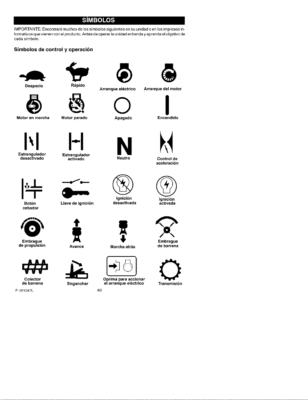
B'_t] KtI-']
IMPORTANTE: Encontrara muchos de los simbolos siguientes en su unidad o en los impresos in-
formativos que vienen con el producto. Antes de operar la unidad entienda y aprenda el objetivo de
cada simbolo.
Simbolos de control y operacion
Despacio Rapido
Arranque el_ctrico Arranque del motor
@ o I
Motor en marcha Motor parado Apagado Encendido
H N
Estrangulador Estrangulador
desactivado activado Neutro Control de
aceleracion
Boton Llave de ignicion
cebador
Embrague
de propulsion
Colector
de barrena
F-011047L
® @
Ignicion Ignicion
desactivada activada
Avance Marcha atras de barrena
O_onar 0
Enganchar el arranque electrico Transmision
40
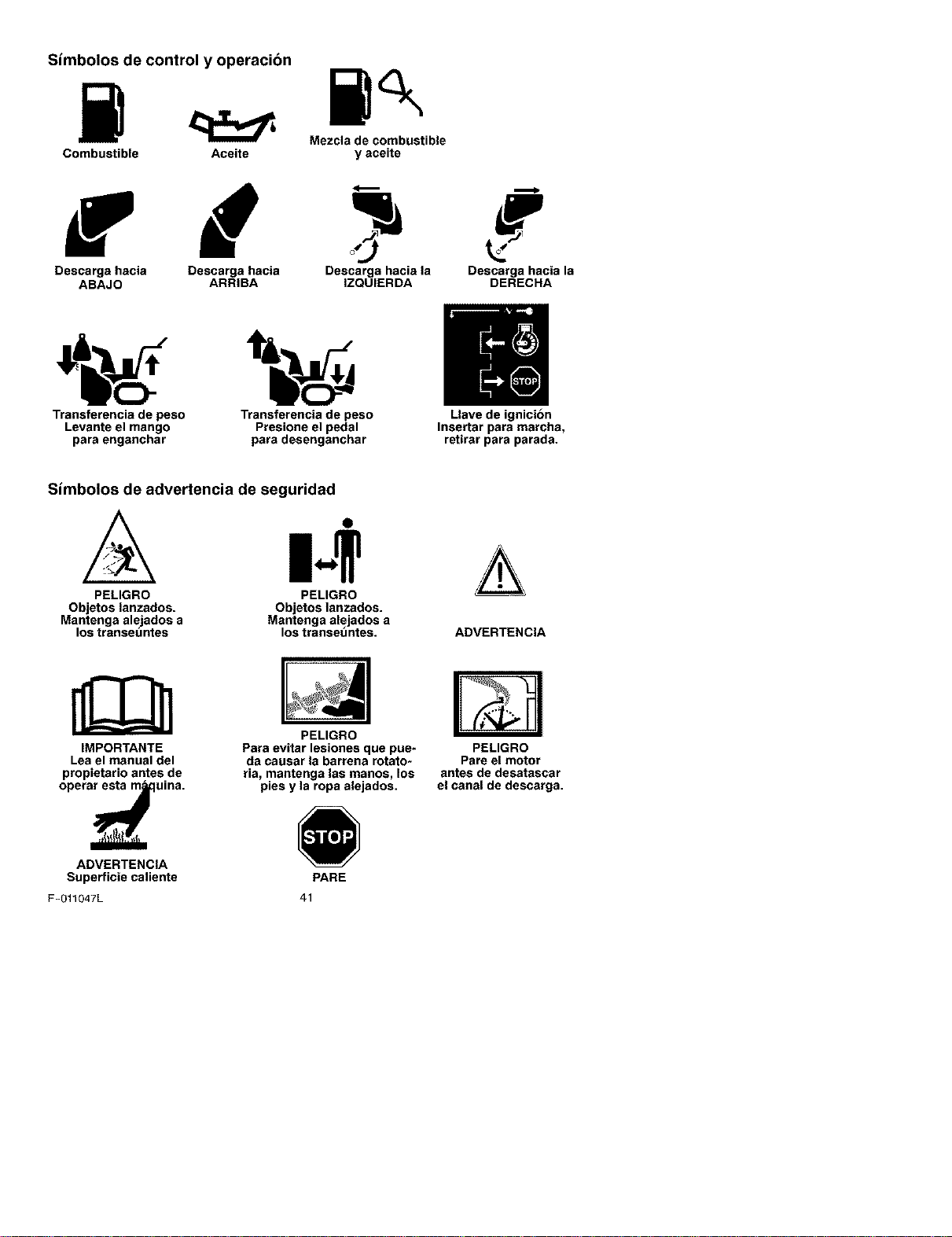
Simbolos de control y operacion
Mezcla de combustible
Combustible Aceite y aceite
Descarga hacia Descarga hacia Descarga hacia la Descarga hacia la
ABAJO ARRIBA IZQUIERDA DERECHA
i' o]
Transterencia de peso Transterencia de peso Llave de ignicibn
Levante el mango Presione el pedal Insertar para marcha,
para enganchar para desenganchar retirar para parada.
Simbolos de advertencia de seguridad
PELIGRO
Objetos lanzados.
Mantenga alejados a
los transauntes
PELIGRO
Objetos lanzados.
Mantenga alejados a
los transet_ntes. ADVERTENCIA
IMPORTANTE
Lea el manual del
propietario antes de
opera_uina.
ADVERTENCIA
Superficie caliente
F-O11047L
PELIGRO
Para evitar lesiones que pue-
da causar la barrena rotato-
ria, mantenga las manos, los
pies y la ropa alejados.
41
PARE
PELIGRO
Pare el motor
antes de desatascar
el canal de descarga.
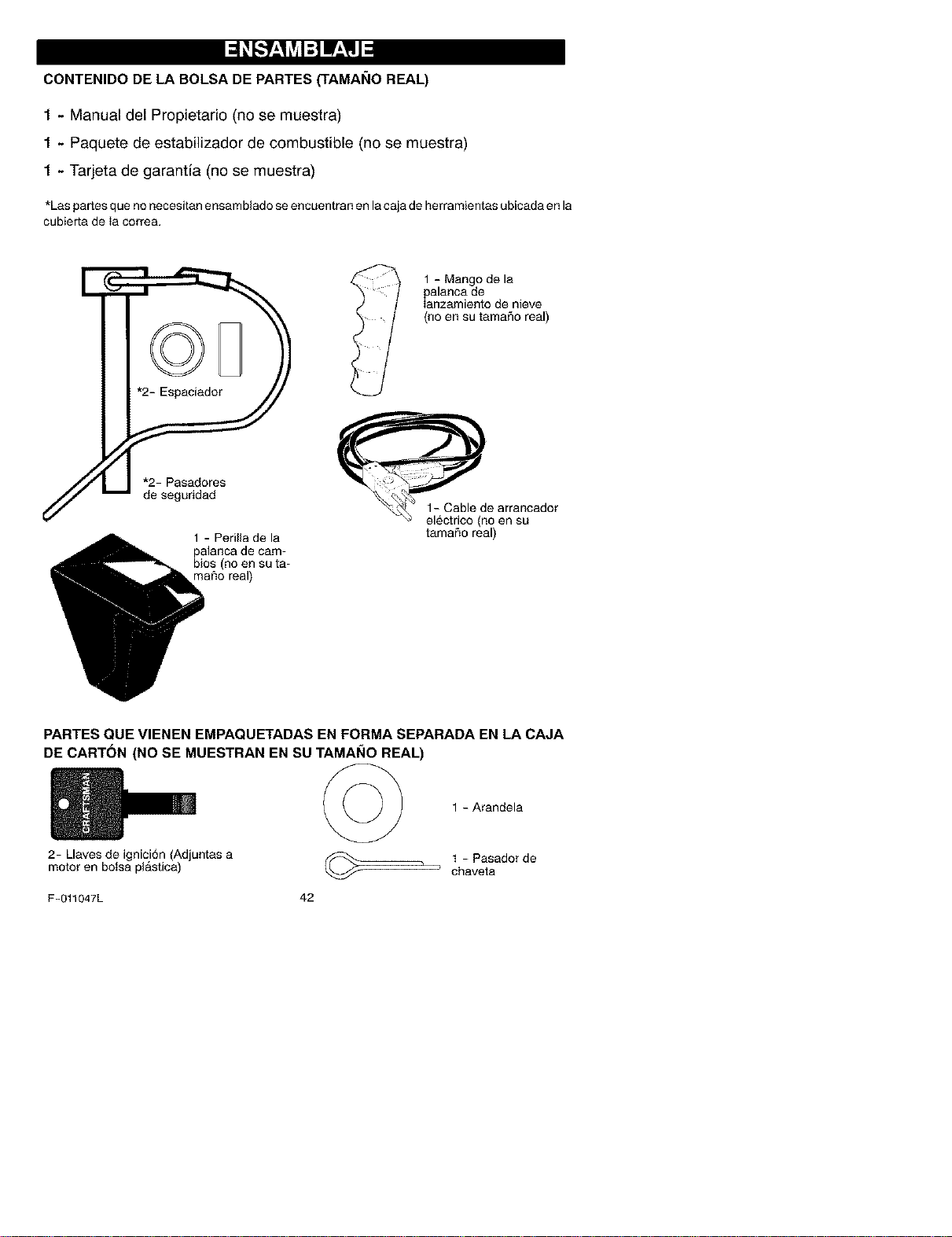
CONTENIDO DE LA BOLSA DE PARTES ('FAMANO REAL)
1 - Manual del Propietario (no se muestra)
1 - Paquete de estabilizador de combustible (no se muestra)
1 - Tarjeta de garantia (no se muestra)
*Las partesque no necesitanensambladeseencuentran enlacajade herramientasubicadaenla
cubierta de ia correa.
1 - Perilla de la
palanca de cam-
bios (no en su ta-
"naRo real)
1 - Mango de la
palanca de
Ianzamiento de nieve
(no en su tamaSo real)
tamaRo real)
PARTES QUE VIENEN EMPAQUETADAS EN FORMA SEPARADA EN LA CAJA
DE CARTON (NO SE MUESTRAN EN SU TAMAI_IO REAL)
2- Llaves de ignici6n (Adjuntas a
motor en botsa plastica)
1 - Arandela
1 - Pasadordechaveta
F-011047L 42
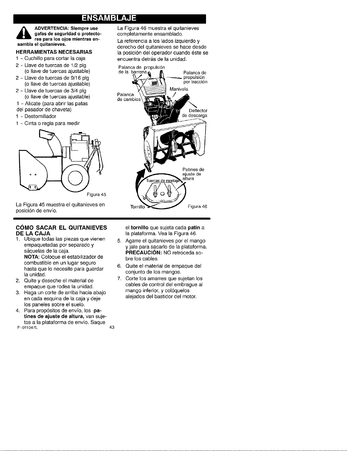
_lb DVERTENCIA: Siempre use
gafas de seguridad o protecto-
res para los ojos mientras en-
sambla el quitanieves.
HERRAMIENTAS NECESARIAS
1 - Cuchillo para cortar la caja
2 - Llave de tuercas de 1/2 pig
(o Ilave de tuercas ajustable)
2 - Llave de tuercas de 9/16 pig
(o Ilave de tuercas ajustable)
2 - Llave de tuercas de 3/4 pig
(o Ilave de tuercas ajustable)
1 - Alicate (para abrir las patas
del pasador de chaveta)
1 - Destornillador
1 - Cinta o regla para medir
Figura 45
La Figura 45 muestra el quitanieves en
posiciSn de envio.
La Figura 46 muestra el quitanieves
completamente ensamblado.
La referencia a los lados izquierdo y
derecho del quitanieves se hace desde
la posiciSn del operador cuando este se
encuentra detr&s de la unidad.
Palancade propulsiSn
de la barrena Palanca de
_.X _y, _lg_ pot tracci6n
_-_ Manivela
Palanca _ /s _
de cambios_.
_ded [_eflector
, escarga
Patines de
ajuste de
altura
Torni Figura 46
COMO SACAR EL QUITANIEVES
DE LA CAJA
1. Ubique todas las piezas que vienen 5.
empaquetadas por separado y
s&quelas de la caja.
NOTA: Coloque el estabilizador de
combustible en un lugar seguro 6.
hasta que Io necesite para guardar
la unidad.
2. Quite y deseche el material de 7.
empaque que rodea la unidad.
3. Haga un corte de arriba hacia abajo
en cada esquina de la caja y deje
los paneles sobre el suelo.
4. Para prop6sitos de envio, los ps-
tines de sjuste de altura, van suje-
tos a la plataforma de envio. Saque
F-011047L 43
el tornillo que sujeta cada pstin a
la plataforma. Vea la Figura 46.
Agarre el quitanieves per el mango
y jale para sacarlo de la plataforma.
PRECAUCION: NO retroceda so-
bre los cables.
Quite el material de empaque del
conjunto de los mangos.
Corte los amarres que sujetan los
cables de control del embrague al
mango inferior, y col6quelos
alejados del bastidor del motor.
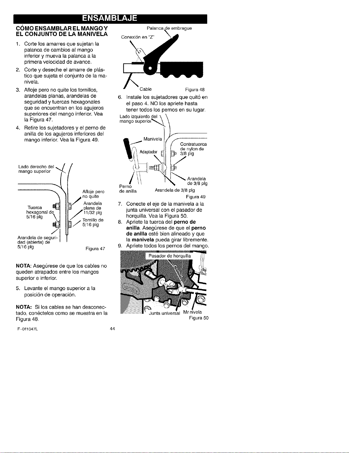
COMO ENSAMBLAR EL MANGOY
EL CONJUNTO DE LA MANIVELA
1. Corte los amarres que sujetan la
palanca de cambios al mango
inferior y mueva la palanca a la
primera velocidad de avance.
2. Corte y deseche el amarre de pl&s-
tico que sujeta el conjunto de la ma-
nivela.
3. Afloje pero no quite los tornillos,
arandelas planas, arandelas de
seguridad y tuercas hexagonales
que se encuentran en los agujeros
superiores del mango inferior. Vea
la Figura 47.
4. Retire los sujetadores y el perno de
anilla de los agujeros inferiores del
mango inferior. Vea la Figura 49.
Conexi6n en "Z"
Cable Figura48
6. Instale los sujetadores que quit5 en
el paso 4. NO los apriete hasta
tener todos los pernos en su lugar.
Lado izquierdo del
mango superiol_
Contratuerca
de nylon de
3/8 pig
mango superior
Tuerca
5/16 pig
Arandela de seguri-
dad (abierta) de
5/16 pig
Afloje pero
no quite
Arandela
• Tornillo de
5/16 pig
Figura 47
Arandela
Pemo de 3/8 pig
de anilla Arandela de 3/8 pig
Figura 49
7. Conecte el eje de la manivela a la
junta universal con el pasador de
horquilla. Vea la Figura 50.
8. Apriete la tuerca del perno de
anilla. AsegQrese de que el perno
de anilla este bien alineado y que
la manivela pueda girar libremente.
9. Apriete todos los pernos del mango.
NOTA: AsegQrese de que los cables no
queden atrapados entre los mangos
superior e inferior.
5. Levante el mango superior a la
posici6n de operaci6n.
NOTA: Si los cables se han desconec-
tado, conectelos come se muestra en la
Figura 48.
F-011047L
44
Junta universal
Figura 50
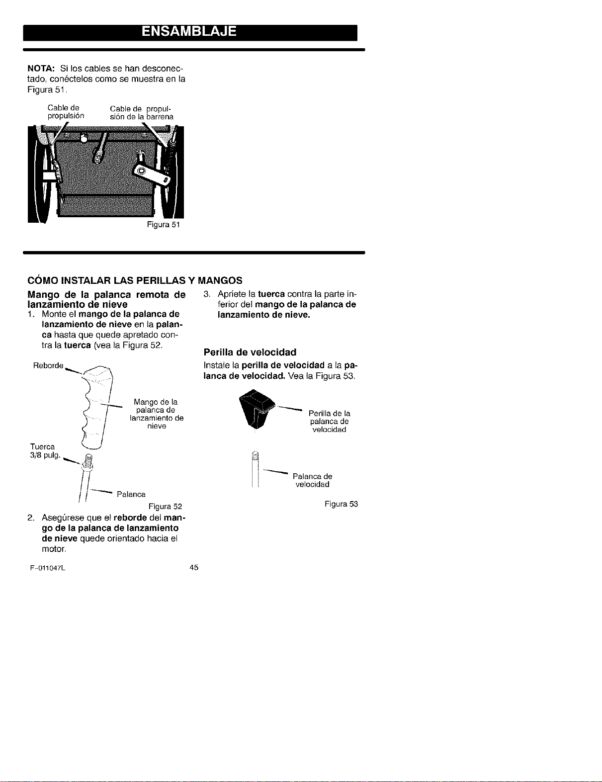
NOTA: Si los cables se han desconec-
tado, conectelos come se muestra en la
Figura 51.
Cable de Cable de propul-
propulsi6n si6n de la barrena
Figura 51
COMO INSTALAR LAS PERILLAS Y MANGOS
Mango de la palanca remota de
lanzamiento de nieve
1. Monte el mango de la palanca de
lanzamiento de nieve en la palan-
ca hasta que quede apretado con-
tra la tuerca (vea la Figura 52.
Reborde _..
Tuerca
3/8 pulg.
Mango de la
palanca de
Ianzamiento de
nieve
//_"" Palanca
Figura 52
2. AsegQrese que el reborde del man-
go de la palanea de lanzamiento
de nieve quede orientado hacia el
motor.
3. Apdete la tuerca contra la parte in-
ferior del mango de la palanca de
lanzamiento de nieve.
Perilla de velocidad
Instale la perilla de velocidad a la pa-
lanca de velocidad. Vea la Figura 53.
_'-"_ erillade la
palanca de
vetocidad
_ _ Palanca de
velocidad
Figura 53
F-011047L 45
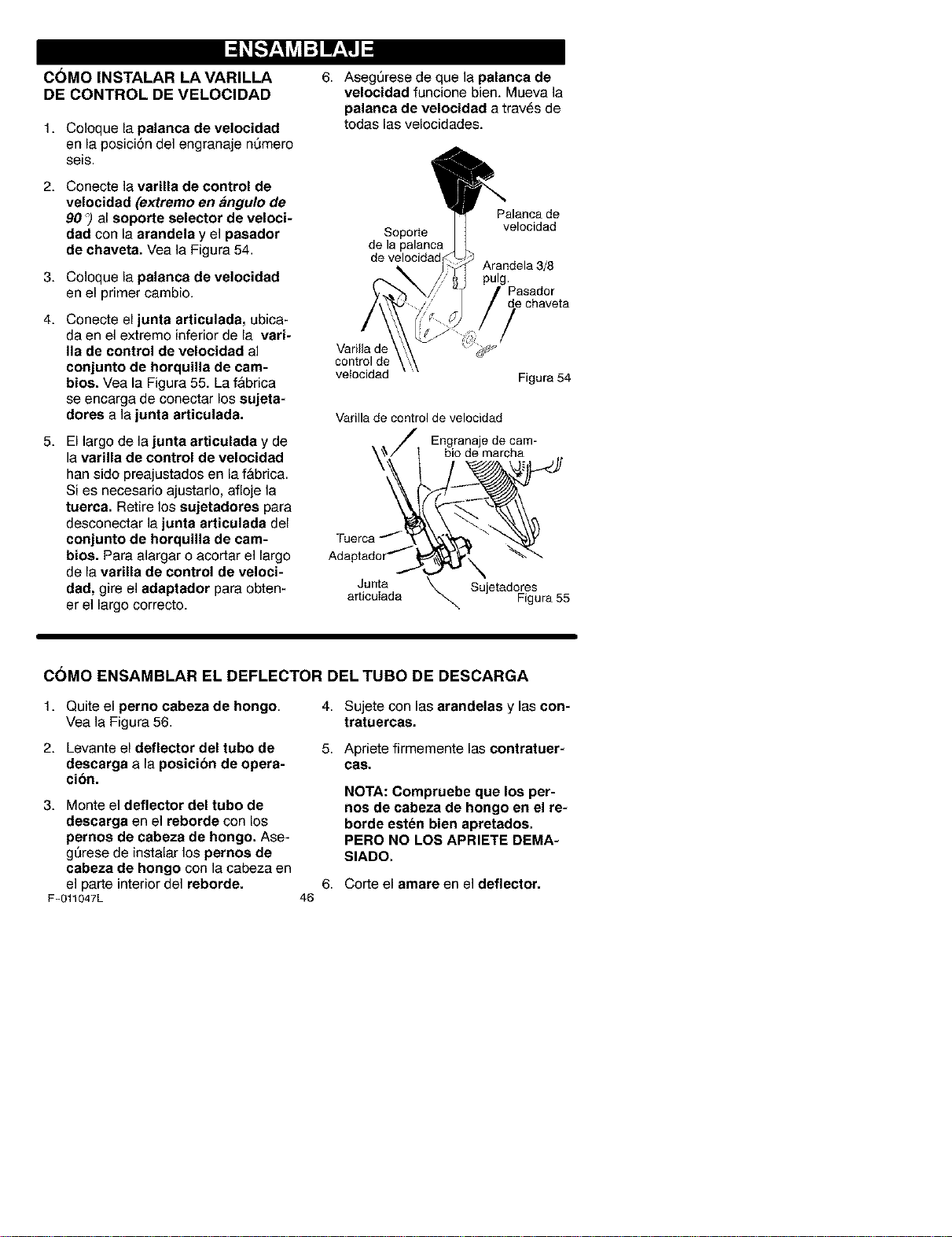
COMO INSTALAR LA VARILLA
DE CONTROL DE VELOCIDAD
1. Coloque la palanca de velocidad
en la posici6n del engranaje nQmero
seis.
2. Conecte la varilla de control de
velocidad (extremo en ,_ngulo de
90 _)al soporte selector de veloci-
dad con la arandela y el pasador
de chaveta. Vea la Figura 54.
3. Coloque la palanca de velocidad
en el primer cambio.
4. Conecte el junta articulada, ubica-
da en el extreme inferior de la vari-
lie de control de velocidad al
conjunto de horquilla de cam-
bios. Vea la Figure 55. La f&brica
se encarga de conectar los sujeta-
dores ala junta articulada.
5. El largo de la junta articulada y de
la varilla de control de velocidad
han side preajustados en lafabrica.
Si es necesario ajustarlo, afloje la
tuerca. Retire los sujetadores para
desconectar la junta articulada del
conjunto de horquilla de cam-
bios. Para alargar o acortar el largo
de la varilla de control de veloci-
dad, gire el adaptador para obten-
er el largo correcto.
6. Aseg_rese de que la palanca de
velocidad funcione bien. Mueva la
palanca de velocidad a tray,s de
todas las velocidades.
Palanca de
Soporte velocidad
de la palanca
Arandela 3/8
pulg.
Pasador
de chaveta
Varilla de
control de
vetocidad
Figure 54
Varilla de control de velocidad
Engranaje de cam-
bio de marcha
Adaptador _ ',
Junta _ SujetadoresarticuIada Figure 55
C(_MO ENSAMBLAR EL DEFLECTOR DEL TUBO DE DESCARGA
1. Quite el perno cabeza de hongo. 4.
Yea la Figura 56.
5.
2. Levante el deflector del tubo de
descarga ala posicion de opera-
cion.
3. Monte el deflector del tubo de
descarge en el reborde con los
pernos de cabeza de hongo. Ase-
gSrese de instalar los pernos de
cabeza de hongo con la cabeza en
el parte interior del reborde.
F-011047L
6,
46
Sujetecon lasarandelas y las con-
tratuercas.
Apriete firmemente las contratuer-
ces.
NOTA: Compruebe que los per-
nos de cabeza de hongo en el re-
borde esten bien apretados.
PERO NO LOS APRIETE DEMA-
SIADO.
Corte el amare en el deflector.
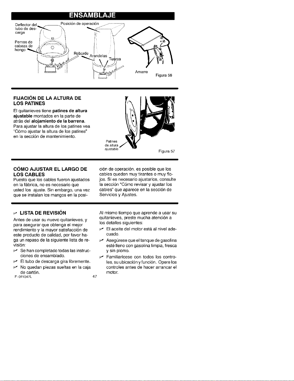
Deflectordel Posici6ndeoperaci6n
tubodedes-/_-_.--_
Pernosde/ _ /:
cabeza de
hongo _S O _
___--_ Reborde /
_J Arandelas ,
Amarre
Figura 56
FIJACION DE LA ALTURA DE
LOS PATINES
El quitanieves tiene patines de altura
ajustable montados en la parte de
atr&s del alojamiento de la barrena.
Para ajustar la altura de los patines vea
"C6mo ajustar la altura de los patines"
en la secci6n de mantenimiento.
Patines
de altura
ajustable
Figura 57
C()MO AJUSTAR EL LARGO DE
LOS CABLES
Puesto que los cables fueron ajustados
en la f&brica, no es necesario que
usted los ajuste. Sin embargo, una vez
que se instalan los mangos en la posi-
ci6n de operaci6n, es posible que los
cables queden muy tirantes o muy flo-
jos. Si es necesario ajustarlos, consulte
la secci6n "C6mo revisar y ajustar los
cables" que aparece en la secci6n de
Servicios y Ajustes.
_" LISTA DE REVISION
Antes de usar su nuevo quitanieves, y
para asegurar que obtenga el mejor
rendimiento y la mayor satisfacci6n de
este producto de calidad, per favor ha-
ga un repaso de la siguiente lista de re-
visi6n:
w' Se han completado todas las instruc-
ciones de ensamblado.
w' El tubo de descarga gira libremente.
w' No quedan piezas sueltas en la caja
de cart6n.
F-011047L
47
AI mismo tiempo que aprende a usar su
quitanieves, preste mucha atenci6n a
los detalles siguientes:
w' El aceite del motor esta al nivel ade-
cuado.
w' AsegQrese que el tanque de gasolina
este Ileno con gasolina limpia, fresca
y sin plomo.
_-" Familiaricese con todos los centre-
les, su ubicaci6n y funci6n. Opere los
controles antes de hacer arrancar el
motor.
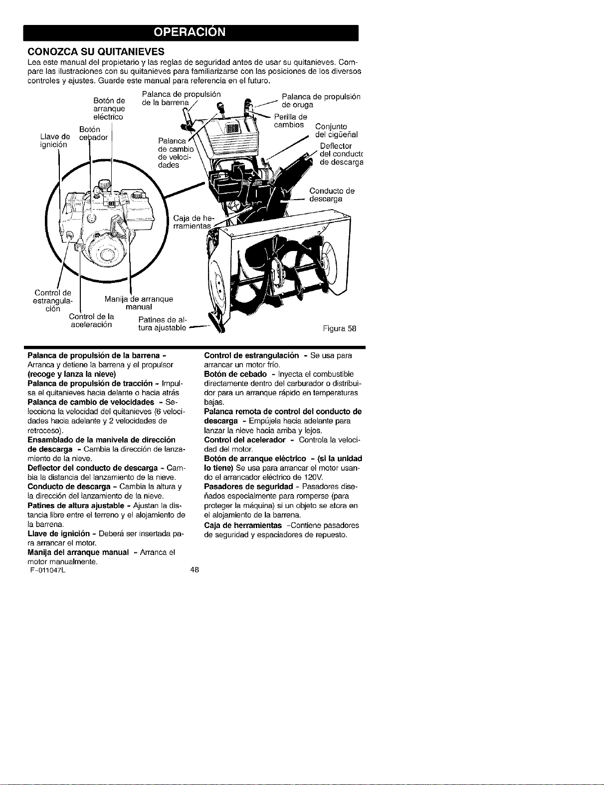
CONOZCA SU QUITANIEVES
Leaeste manual del propietarioy las reglas de seguridad antes de usarsu quitanieves. Com-
pare las ilustraciones con suquitanieves para familiarizarse con lasposiciones de los diversos
oontroles y ajustes. Guarde este manual para referenciaen et futuro.
Palanca de propulsi6n Palanca de propulsi6n
Bot6n de de la barrena / de oruga
arranque
el6ctrico
Bot6n cambios Conjunto
Llave de del cig_eSal
ignici6n Deflector
(
Control de
estra_ngula-
clon
Control de la
aceteraci6n
de cambic
de veloci-
dades de descarga
Manija de arranque
manual
Conducto de
Patines de al-
tura aj Figura 58
Palanca de propulsion de la bar_ena -
Arranca y detiene la barrena y el propulsor
(recoge y lanza la nieve)
Palanca de propulsion de traccibn - Impul-
sa el quitanieves hacia delante o hacia atrAs
Palanca de cambio de velocidades - Se-
Iecciona la velocidad del quitanieves (6 veloci-
dades hacia adelante y 2 velocidades de
retroceso).
Ensamblado de la manivela de direccion
de descarga - Carnbia la direcci6n de Ianza-
mier_o de la nieve.
Deflector del conducto de descarga - Cam-
bia la distancia del lanzamiento de la nieve.
Conducto de descarga - Cambia la altura y
ia direcci6n del ianzamiento de la nieve.
Patines de altura ajustable - Ajustan la dis-
tancia libre entre el terreno y el alojamiento de
la barren&
Llave de ignici6n - Debera ser insertada pa-
ra arranoar el motor,
Manija del arranque manual - Arranca el
motor manualmente.
F-011047L
Control de estrangulacion - Se usa para
arrancar un motor fr_o.
Bot6n de ¢ebado - Inyecta el combustible
directamente dentro del carburador o distribui-
dor para un arranque rApido en temperaturas
bajas.
Palanca remota de control del conducto de
descarga - Ernpt_jela hacia adelante para
lanzar la nieve hacia arriba y lejos.
Control del acelerador - Controla ia veloci-
dad del motor.
Botbn de arranque electrico - (si la unidad
Io tiene) Se usa para arrancar el motor usan-
do el arrancador el@ctdcode 120V,
Pasadores de seguridad - Pasadores dise-
r_adosespecialmente para romperse (para
proteger la maquina) si un objeto se atora en
el alojamiento de la barren&
Caja de herramientas -Contiene pasadores
de seguridad y espaciadores de repuesto.
48
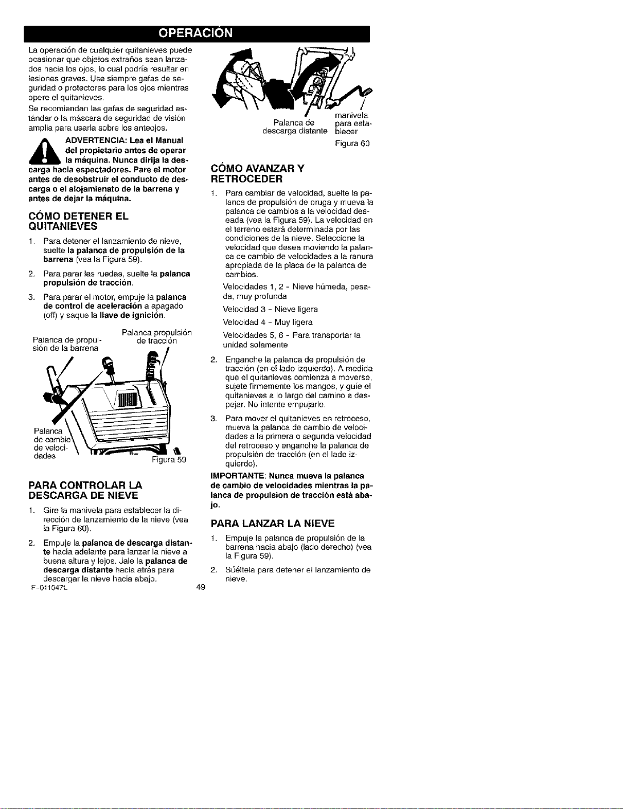
Laoperaci6ndecualquierquitanievespuede
ocasionarqueobjetosextrai_osseanlanza-
doshacialosojos,Iocualpodrfaresultaren
Iesionesgraves.Usesiempregafasdese-
guridadoprotectoresparalosojosmientras
opereelquitanieves.
Serecomiendanlasgafasdeseguridades-
tg=ndarolamascaradeseguridaddevisi6n
ampliaparausarlasobrelosanteojos.
_i ADVERTENCIA: Lea el Manual
del propietario antes de operar
la maquina. Nunca dirija la des-
carga hacia espectadores. Pare el motor
antes de desobstruir el conducto de des-
carga o el alojamienato de la barrena y
antes de dejar la maquina.
C()MO DETENER EL
QUITANIEVES
1. Para detener el lanzamiento de nieve,
suelte la palanca de propulsion de la
barrena (yea la Figura 59).
2. Para parar las ruedas, suelte ia palanca
propolsibn de traccion.
3. Para parar el motor, empuje la palanca
de control de aceleracion a apagado
(off) y saque la Ilave de ignicion.
Palanca de propul-
si6n de la barrena
Palanca propulsi6n
de tracci6n
Palanoa
de veloci-
dades Figura 59
PARA CONTROLAR LA
DESCARGA DE NIEVE
1. Gire la manivela para establecer la di-
recci6n de lanzamiento de la nieve (vea
Ia Figura 60).
2. Empuje la palanca de descarga distan-
te hacia adelante para Ianzar la nieve a
buena altura y lejos. Jale la palanca de
descarga distante hacia atr_s para
descargar la nieve hacia abajo.
F-011047L
Palanca de para esta-
descarga distante blecer
Figura 60
49
COMO AVANZAR Y
RETROCEDER
1. Para cambiar de velocidad, suelte la pa-
lanca de propulsi6n de oruga y mueva la
palanca de cambios a la velocidad des-
eada (vea la Figura 59). La velocidad en
el terreno estar_ determinada pot las
condiciones de la nieve. Seleccione la
velocidad que desea moviendo la palan-
ca de cambio de veloeidades a la ranura
apropiada de la placa de Ia palanca de
cambios.
Velocidades 1,2 - Nieve h[imeda, pesa-
da> muy profunda
VeIocidad 3 - Nieve ligera
Velocidad 4 - Muy ligera
Velocidades 5, 6 - Para transportar ia
unidad solamente
Enganche la palanca de propulsi6n de
tracci6n (en el lado izquierdo). A medida
que el quitanieves comienza a moverse,
sujete firmemente los mangos, y gufe el
quitanieves a Io largo del camino a des-
pejar. No intente empujarlo.
3. Para mover el quitanieves en retroceso,
mueva la palanca de cambio de veloci-
dades a la primera o segunda velocidad
del retroceso y enganche la palanca de
propulsi6n de tracci6n (en el lado iz-
quierdo).
IMPORTANTE: Nunca mueva la palanca
de cambio de velocidades mientras la pa-
lanca de propulsion de traccibn esta aba-
jo.
PARA LANZAR LA NIEVE
1. Empuje la palanca de propulsi6n de la
barrena haeia abajo (lado derecho) (yea
la Figura 59).
2. SL_61telapara detener el lanzamiento de
nieve.
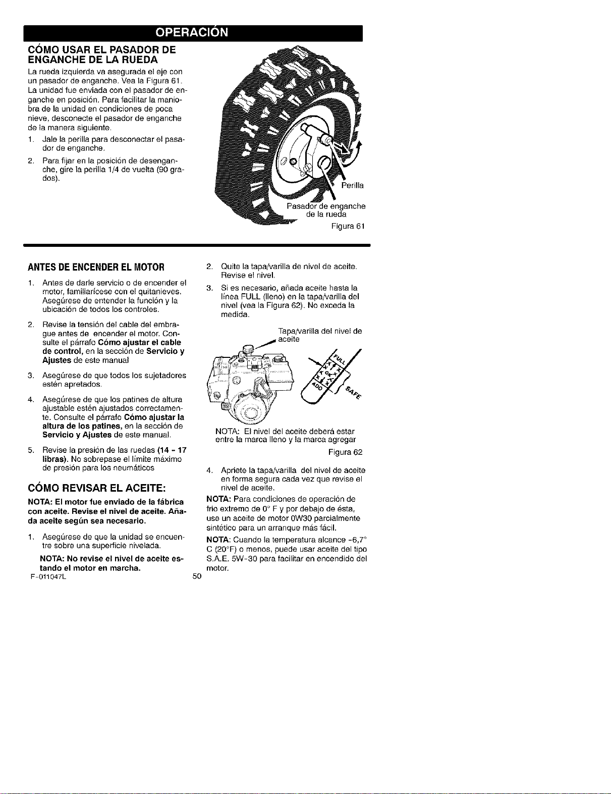
COMO USAR EL PASADOR DE
ENGANCHE DE LA RUEDA
La rueda izquierda va asegurada el eje con
un pasador de enganche. Vea la Figura 61.
La unidad rue enviada con el pasador de en-
ganche en posici6n. Para facilitar la manio-
bra de la unidad en condiciones de poca
nieve, desconecte el pasador de enganche
de ia manera siguiente.
1. Jale la perilla para desconectar ei pasa-
dor de enganche.
2. Para fijar en la posici6n de desengan-
che, gire la perilla 1/4 de vueita (90 gra-
dos).
Perilla
Pasador de enganche
de la rueda
Figura 61
ANTESDEENCENDERELMOTOR
1. Antes de darle servicio o de encender el
motor, famiIiar[cese con el quitanieves.
Asegt_rese de entender la funci6n y la
ubicaci6n de todos los controles.
2. Revise la tensi6n del cable del embra-
gue antes de encender el motor. Con-
suite el parrafo Como ajustar el cable
de control, en la secci6n de Servicio y
Ajustes de este manual
3. Asegt_rese de que todos los sujetadores
esten apretados.
4. AsegL_rese de que los patines de altura
ajustable esten ajustados correctamen-
re. Consulte el parrafo Como ajustar la
altura de los patines, en lasecci6n de
Servicio y Ajustes de este manual
5. Revise la presi6n de las ruedas (14 - 17
libras). No sobrepase el llmite m_ximo
de presi6n para los neumAticos
C()MO REVISAR EL ACEITE:
NOTA: El motor fue enviado de la f_brica
con aceite. Revise el nivel de aceite. A_a-
da aceite segt_n sea necesario.
1. Asegt_rese de que la unidad se encuen-
tre sobre una superficie niveIada.
NOTA: No revise el nivel de aceite es-
tando el motor en marcha.
F-011047L
2. Quite la tapa/varilla de nivel de aceite.
Revise el nivel.
3. Si es necesario, aflada aceite hasta la
I[nea FULL (lleno) en la tapa/varilla del
nivel (vea la Figura 62). No exceda Ia
medida.
Tapa/variila det nivet de
j aceite
5O
NOTA: El nivel del aceite debera estar
entre la marca Ileno y Ia marca agregar
Figura 62
4. Apriete la tapa/varilla del nivel de aceite
en forma segura oada vez que revise el
nivel de aceite.
NOTA: Para condiciones de operaci6n de
frio extremo de 0° F y pot debajo de esta,
use un aceite de motor 0W30 parcialmente
sintetico para un arranque mAs facil.
NOT,&: Cuando la temperatura alcance -6,7 °
C (20°F) o rnenos, puede usar aceite del tipo
S.A.E. 5W-30 para facilitar en encendido del
motor.
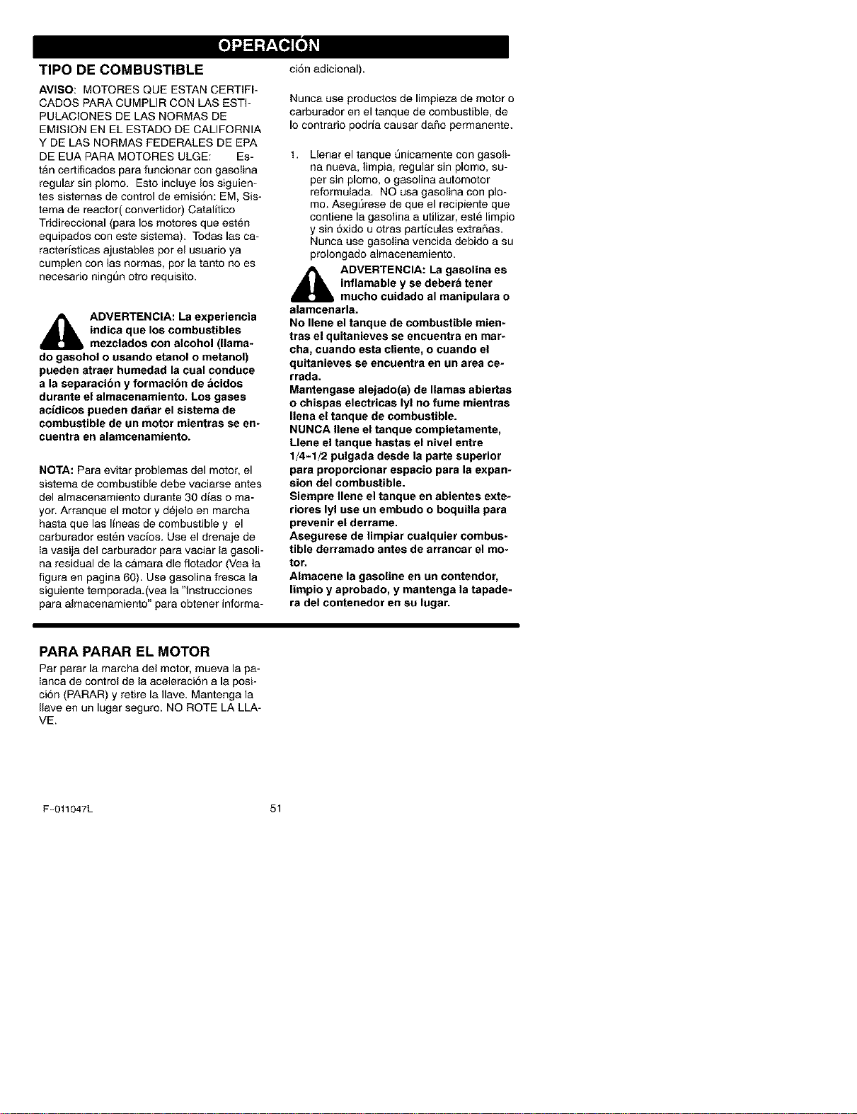
TIPO DE COMBUSTIBLE
AVISO: MOTORES QUE ESTAN CERTIFI-
CADOS PARA CUMPLIR CON LAS ESTF
PULACIONES DE LAS NORMAS DE
EMISION EN EL ESTADO DE CALIFORNIA
Y DE LAS NORMAS FEDERALES DE EPA
DE EUA PARA MOTORES ULGE: Es-
tg=ncertificados para funcionar con gasoIina
regular sin plomo. Esto incluye los siguien-
tes sistemas de control de emisi6n: EM, Sis-
tema de reactor(convertidor) Catalitico
Tridireccional (para los motores que esten
equipados con este sistema). Todas las ca-
racteristicas ajustables por el usuario ya
cumplen con las normas, pot la tanto no es
necesario ning_n otro requisito.
_ DVERTENCIA: La experiencia
indica que los combustibles
mezclados con alcohol (llama-
do gasohol o usando etanol o metanol)
pueden atraer humedad la cual conduce
a la separacion y formacion de _cidos
durante el almacenamiento. Los gases
acidicos pueden da_ar el sistema de
combustible de un motor mientras se en-
cuentra en alamcenamiento.
NOTA: Para evitar problemas del motor, el
sistema de combustible debe vaciarse antes
del almacenamiento durante 30 dias o ma-
yor. Arranque el motor y dejelo en marcha
hasta que las lineas de combustible y el
carburador esten vacios. Use el drenaje de
Ia vasija del carburador para vaciar la gasoli-
na residual de la camara die fiotador (Vea la
figura en pagina 60). Use gasolina fresca la
siguiente temporada.(vea la "lnstrucciones
para almacenamiento" para obtener informa-
ci6n adicional).
Nunca use productos de limpieza de motor o
carburador en el tanque de combustible, de
Io contrario podria causar daflo permanente.
1. Llenar el tanque t3nicamente con gasoli-
na nueva, limpia, regular sin plomo, su-
per sin plomo, o gasolina automotor
reformulada. NO usa gasolina con plo-
mo. AsegSrese de que el recipiente que
contiene la gasolina a utilizar, est@ limpio
y sin 6xido u otras particulas extrar_as.
Nunca use gasoiina vencida debido a su
prolongado almacenamiento.
_ DVERTENGIA: La gasolina es
inflamable y se debera tener
muoho cuidado al manipulara o
alamcenarla.
No Ilene el tanque de combustible mien-
tras el quitanieves se encuentra en mar-
cha, cuando esta cliente, o cuando el
quitanieves se encuentra en un area ce-
rrada.
Mantengase alejado(a) de llamas abiertas
o chispas electricas lyl no fume mientras
Ilena el tanque de combustible.
NUNCA liens el tanque completamente,
Llene el tanque hastas el nivel entre
1/4-1/2 pulgada desde la parte superior
para proporcionar espacio para la expan-
sion del combustible.
Siemprs Ilene el tanque en abientes exte-
riores lyl use un embudo o boquilla para
prevenir el derrame.
Asegurese de limpiar cualquier combus-
tible derramado antes de arrancar el mo-
tor.
Almacene la gasoline en un contendor,
limpio y aprobado, y mantenga la tapade-
ra del contenedor en su lugar.
PARA PARAR EL MOTOR
Par parar la marcha del motor, mueva la pa-
Ianca de control de la aceleraci6n a la posi-
ci6n (PARAR) y retire la Ilave. Mantenga la
Ilave en un lugar seguro. NO ROTE LA LLA-
VE.
F-011047L 51
PARA ARRANCAR EL MOTOR
(arrancador eldctrico)
Asegt3rese de que el motor tenga suficiente
acelte. El motor de el quitanieves esta equi-
patio con un arrancador electrico de 120 vot-
tios corrlente altema y arrancador de
retroceso. Antes de arranoar el motor, ase-
gSrese de haber leido la informaci6n si-
guiente:
_hb ADVERTENCIA: Este arranca-
dor esta equipado con un cable
de alimentacion trifilar y esta
disef_ado para operar en corriente alterna
domiciliar de 120 voltios. Debera estar
conectado a tierra de manera adecuada
en todo momento para evitar la posibili-
dad de un choque electrico, el cual po-
dria causar heridas al operador. Siga las
instrucciones cuidadosamente de la ma-
hera en que se detallan en la seccion
"Para arranca el motor." Verifique que el
alambrado de su casa sea trifilar con po-
lo a tierra. Pregunte a un electricista au-
torizado si no se encuentra seguro. Si el
sistema de alambrado de su casa no es
un sistema trifllar, no use el arrancador
electrico bajo ninguna condicion. Si su
sistema tiene polo a tierra y no se en-
cuentra disponible un receptaculo trifilar
en el punto en que su arrancador sera
usado normalmente, se debe instalar uno
por un electricista autorizado. AI conec-
tar el cable de alimentacion electrioa de
corriente alterna de 120 voltios, siempre
conecte el cable a la caja de interrupto-
res en el motor primero, luego enchufe el
otto extremo en el receptaculo trifilar con
polo a tierra. AI desconectar el cable de
alimentacion electrica, siempre des en-
chufe el extremo en el receptaculo con
polo a tierra primero.
ARRANQUE EN FRIO
1. Asegt_rese de que las palancas de pro-
pulsi6n del barreno y de propulsi6n de
oruga estAn en la posici6n desengan-
chada "SU ELTA" (RELEASED).
2. Mueva el control de la aceleraci6n a la
posici6n (RAPIDO).
3. Remueva las Ilaves de la botsa plastic&
Inserte una IIave en la ranura de ignl-
F-011047L
52
ci6n. NO ROTE LA LLAVE. Mantenga la
segunda Ilave en un lugar seguro.
4. Rote la manecilla de estrangulaci6n a la
posici6n estrangulaci6n 'q-OTAL"
(FULL).
5. Conecte el cable de alimentaci6n electri-
ca a la oaja de interruptores en el motor.
6. Enchufe el otro extremo del cable de ali-
mentaci6n electrica en un recept_culo
trifilar de t 20 voltios y corriente altema
con polo a tierra.
10.
Empuje el bot6n cebo mientras cubre el
agujero de ventilaci6n de la manera si-
guiente: (Remueva el dedo deI bot6n ce-
bo entre cebados).
No efectSe el cebado si la temperatura
est sobre 50° R
Dos veces si la temperatura esta entre
50°F to 15°R
Cuatro veces si la temperatura se en-
cuentra por debajo de 15°R
Empuje el bot6n del arrancador hacia
abajo hasta que el motor arranque. No
intentar el arranque por mas de 10 ser-
gundos a la vez. Este arrancador el_ctri-
co estA protegido termalmente. Si se
sobre calienta se detendra automatica-
mente y puede set arranoado nueva-
mente s61o cuando se ha enfriado hasta
una temperatura segura (se requiere
una espera de 5 a 10 minutos aproxima-
damente).
Cuando el motor arranque, suelte el bo-
tan de arranque y ponga la palanca del
ahogador en la posici6n "1/2 ahogador".
Cuando el motor este trabajando unifor-
memente, meueva la palanca del ahoga-
dora la posici6n "no ahogador".
Desconecte el cable de alimentaci6n
electrica desde el receptaculo primero y
luego desde la caja de interruptores en
ei motor.
NOTA: deje que el motor se caliente por
algunos minutos antes de sopIar nieve, en
temperaturas inferiores a - 18°C (0°F).
11. Opere el motor a toda velocidad (R_,PI-
DO) cuando este lanzando nieve.
ARRANQUE EN CALIENTE
Siesta arrancando un motor caliente des-
pues de un apag6n corto, deje el estrangula-
dot en "APAGADO" (OFF) y no pulse el
bot6n cebo.

PARA ENCENDER EL MOTOR
(retroceso manual)
Cerci6rese de que el motor tiene suficiente
aceite. Antes de encender el motor, asegt_re-
se de leer toda Ia informaci6n siguiente:
ARRANQUE EN FRIO
1. Asegt_rese de que las palancas de pro-
pulsi6n del barreno y de propulsi6n de
oruga estAn en la posici6n desenganche
"SUELTA" (RELEASED).
2. Mueva el control de la aceleraci6n a la
posici6n (RAPIDO).
3. Introduzca la Ilave en la ranura del en-
cendido y asergt)rese de que calce bien.
NO LA HAGA GIRAR. Coloque Ia Ilave
adicional proporcionada en un lugar se-
guro.
4. Rote la manecilla de estrangulaci6n a la
posici6n estrangulaci6n "TOTAL"
(FULL).
5. Empuje el bot6n cebo mientras cubre el
agujero de ventilaci6n de la manera si-
guiente: (Remueva el dedo del bot6n ce-
bo entre cebados).
No efectt3e el cebado si la temperatura
esta sobre 50"R
Dos veces si la temperatura estA entre
50°F hasta15°R
Cuatro veces si la temperatura se
encuentra por debajo de15°R
6. Jale la maniveIa del arranque con un
movimiento seguro y rApido. No deje
que la inercia del encendido hale la
cuerda del arranque con violencia. Per-
mira que vuelva a enrollarse suavemen-
te mientras sostiene ia manivela.
7. Mientras el motor se va calentando,
mueva la palanca de ahogador a la posi-
ci6n de "1/2 ahogador". Cuando el mo-
tor este funcionando uniformemente,
mueva la paIanca del ahogador a la po-
sici6n de "No ahogador'.
NOTA: deje que el motor se caliente pot
algunos minutos antes de soplar nieve, en
temperaturas inferiores a - 18°C (0¢'F).
8. Opere el motor a toda velocidad (RAPI-
DO) al remover nieve.
F-011047L
53
ARRANQUE EN CALIENTE
Si esta arrancando un motor caliente des-
pues de un apag6n corto, deje el estrangula-
dor en "APAGADO" (OFF) y no pulse el
bot6n cebo.
ARRANQUE CONGELADO
Si el arrancador est_ congelado y no arranca
el motor:
1. Hale tanta Iongiatud de cuerda del arran-
cador como sea posible.
2. Suelte la manija del arrancador y d6jela
enrollarse de nuevo contra el arranca-
dot.
Si el motor todavia no arranca, repita estos
pasos hasta que Iogre encnederlo.
Para ayudar a evitar la posibilidad de conge-
lamiento del arrancador de retroceso y los
controles del motor, proceda de la manera
siguiente despues de cada trabajo de remo-
ci6n de nieve.
Con el motor en marcha, hale la cuerda
de arranque energicamente con un alar-
gamiento de brazo continuo tres o cua-
tro veces. El halado de la cuerda de
arranque producirA un sonido de repi-
queteo fuerte. Esto no causa daflo ni al
motor ni al arranoador.
Con el motor parado, limpie toda la nie-
ve y humedad de Ia cubierta del carbu-
rador en el Area de las palancas de
control. Asimismo, mueve el control de
aceleraci6n, control de estrangulaci6n, y
manija del arrancador varias veces y de-
je el estrangulador en la posici6n, "TO-
TAL" (FULL) y la palanca de aceleraci6n
el la posici6n (RAPIDO).
l_ ADVERTENCIA: Nuncs encien-
da el motor de la unidad en re-
cintos cerrados o con poca
ventilacion. Las emanaciones del escape
del motor contienen MONOXIDO DE
CARBONO, UN GAS INOLORO Y MOR-
TAL. Mantenga las manos, pies, cabello y
ropa suelta alejados de cualquier parte
en moviento del motor y de la unidad.
La temperaturs del silenciador y las
areas cercanas a _ste pueden alcanzar
temperaturas de hasta 150 grados F. No
toque estas &reas. NO permita que ni_os
o jovenes utilicen la unidad ni que se en-
cuentren cerca de esta cuando esta fun-
cionando.
_ DVERTENCIA: No intente qui-
tar ningt_n objeto que se haya
atorado en la barrena sin tomar
as precauciones siguientes:
Suelte las palancas de propulsion de
la barrena y de propulsion de traccibn.
Mueva la palanca de control de la ace-
leracion a la posicion parar.
Remueva (no rote) la Ilave de ignicion.
Dssconecte el alambre de la bujia.
No coloque las manos en la barrena o
conducto de descarga. Use una barra
de apalancamiento.
PISTAS SOBRE LANZAMIENTO
DE NIEVE
1. Para mayor eficiencia de lanzamiento de
nieve durante la remoci6n de la misma,
ajuste la velocidad en el terreno, NUN-
CA Ia aceleraciSn, Avance lentamente
en nieve profunda, congelada, o hSme-
da. Si la oruga desliza, reduzca la velo-
cidad hacia adelante. El motor esta
diser_ado para brindar un rendimiento
m_ximo bajo aceleraci6n total y debe
ser operado en este valor de potencia
en todo momento.
2. El lanzamiento de nieve es mas efixcen-
te si Ia remoci6n de la misma se efectt_a
inmediatamente despues de su caida.
3. Para una remociSn completa de la nieve,
traslape ligeramente carla camino adop-
tado previamente. En nieve profunda,
superponga los barridos entre si para
evitar sobrecargar Ia maquina.
4. La nieve debeda set descargada en la
direcciSn del viento siempre que sea po-
sible.
5. Para uso normal, posioione las correde-
ras de apoyo de manera tal que la barra
raspadora se encuentre 1/8 de pulgada
sobre las correderas de apoyo. Para su-
perficies de nieve dura extremadamente
compacta, ajuste las correderas de apo-
yo hacia arriba de manera que la barra
raspadora haga contacto con el terreno.
6. En superficies de grava o roca triturada,
posicione las correderas de apoyo a
1-1/4 pulgadas por debaio de la barra
raspadora (Vea el parrafo "C6mo ajustar
la altura de las correderas de apoyo" en
la pAgina 55). Las rocas y grava no de-
berAn set recogidas y lanzadas pot la
maquina.
7, Despu6s de que se haya completado el
lanzamiento de nieve, permita que el
motor se encuentre en reposo por unos
cuantos minutos, Io cuaI derretirA Ia nie-
ve y hielo acumulado del motor.
8. Efect_e una limpieza completa de el qui-
tanieves luego de cada uso.
9. Remueva la acumulaciSn de hielo y nie-
ve y todo material extraflo heterogeneo
de el quitanieves en su totalidad, y lave
con agua (si fuese posible) para remo-
ver toda sal u otras substancias qu[mi-
cas. Seque el quitanieves.
F-011047L 54
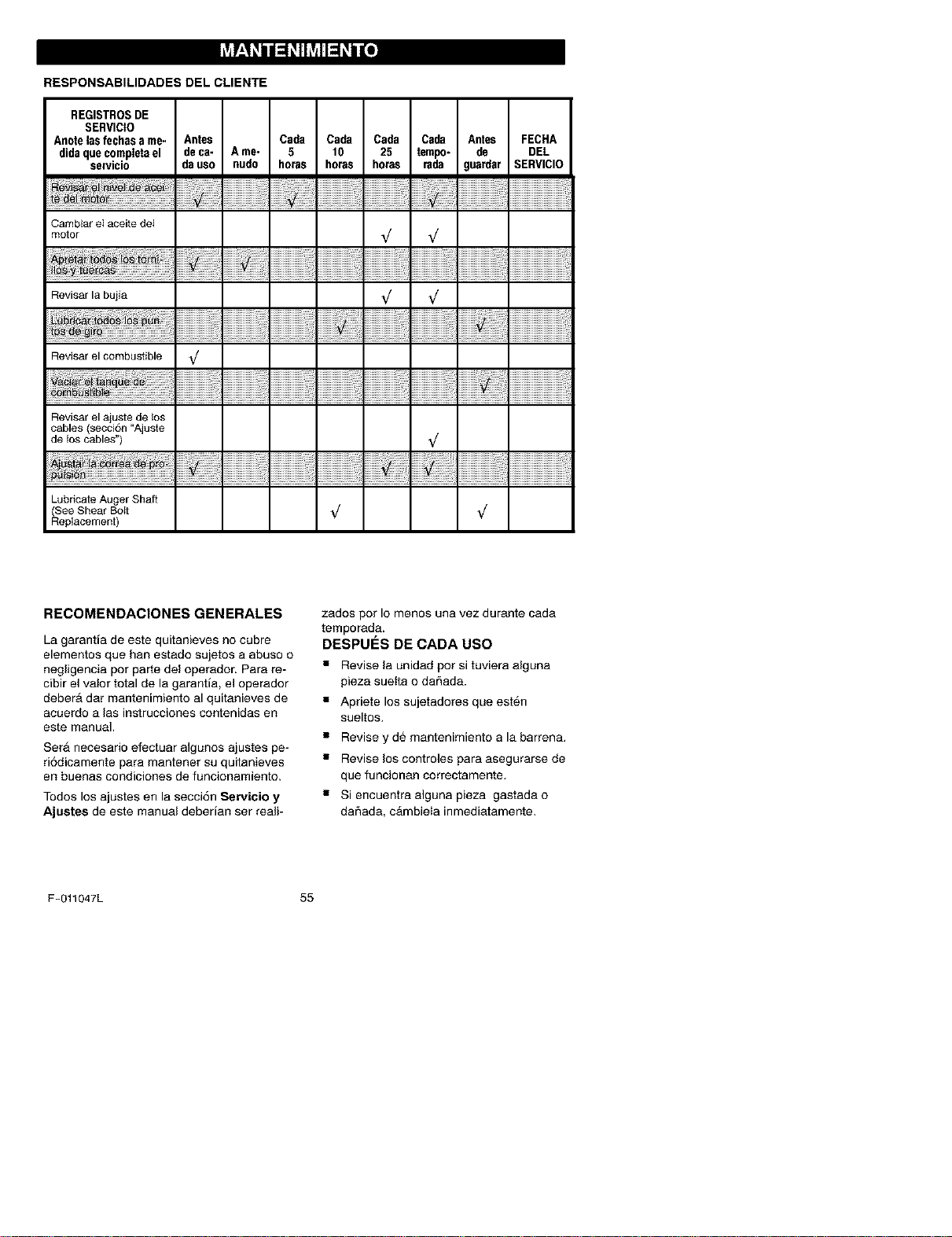
RESPONSABILIDADES DEL CLIENTE
REGISTROSDE
SERVICIO
Anotelas fechsssme- Antes Cada Cada Cada Csda Antes FECHA
didaque completsel deca- A me- 5 10 25 tempo- de DEL
servicio da uso nudo horas horas horas rada guardar SERVICIO
Cambiar eI aceitedel
motor
Revisar la bujia
to_ _!! ..............................................................................
Revisar el combustible %/
. ::
_t!_! ............................................................................
Revisar el ajuste de los
cables (secci6n "Ajuste
de los cables")
i!i!i!i!i!i!i!i!i!i!i!i!i!i!i!i!i!iiii'ii'il_ii_i!i_ii!i!i!i!i!i!i!i!i!i!i!i!i!i!i!i!i!i!iiii'ii'ii_ii_i!
LubricateAugerShaft
See Shear Bolt _/
Replacement)
V
V
V
V
V
V
!i!i!i!i!i!i!i!i!i!i!i!i!i!i!i!i!i!i!i!i!i!i!i!i!i!i!i!iiiiiiii_i
!i!i!i!i!i!i!i!i!i!i!i!i!i!i!i!i!i!i!i!i!i!i!i!i!i!i!i!iiiiiiii_i
!i!i!i!i!i!i!i!i!i!i!i!i!i!i!i!i!i!i!i!i!i!i!i!i!i!i!i!_i_i_iii_i
!i!i!i!i!i!i!i!i!i!i!i!i!i!i!i!i!i!i!i!i!i!i!i!i!i!i!i!iiiiiiii_i
RECOMENDACIONESGENERALES
La garant[a de este quitanieves no cubre
elementos que han estado sujetos a abuso o
negligencia pot parte del operador. Para re-
cibir el valor total de la garantia, el operador
deberA dar mantenimiento al quitanieves de
acuerdo a las instrucciones contenidas ell
este manual.
Ser_ necesario efectuar algunos ajustes pe-
ri6dicamente para mantener su quitanieves
en buenas condiciones de funcionamiento.
Todos los ajustes en la secci6n Servicio y
Ajustes de este manual deberian ser reali-
zados por Io menos una vez durante cada
temporada.
DESPUES DE CADA USO
• Revise la unidad pot si tuviera alguna
pieza suetta o da_ada.
• Apriete los sujetadores que est6n
sueltos.
• Revise y de mantenimiento a la barrena.
• Revise los controles para asegurarse de
que funcionan correctamente.
• Si encuentra alguna pieza gastada o
daSada, cAmbiela inmediatamente.
F-011047L 55
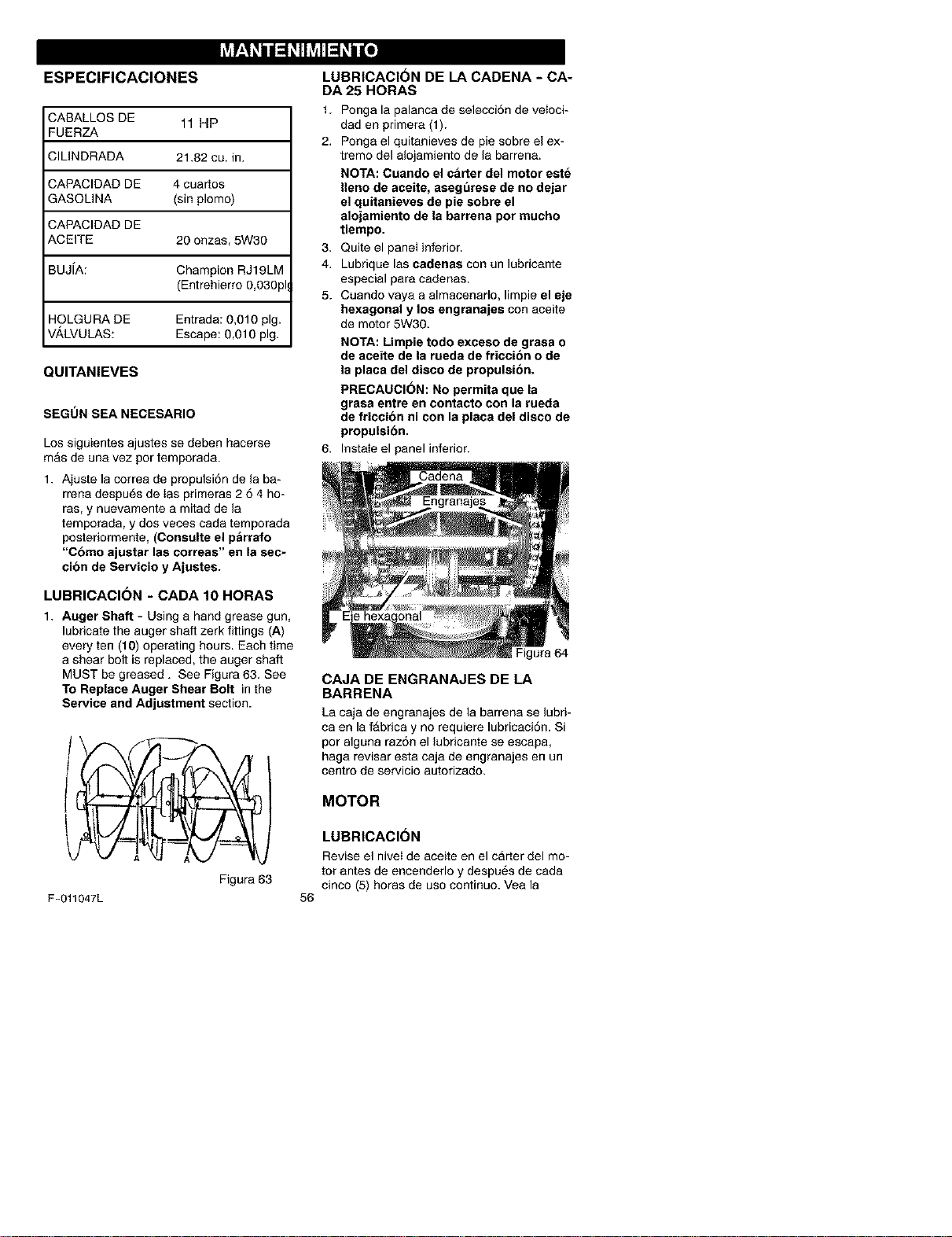
I_VJr-4_ii_ _1hVJIl__it_o]
ESPECIFICACIONES
CABALLOS DE 11 HP
FUERZA
CILINDRADA 21.82 cu. in.
CAPACIDAD DE 4 cuartos
GASOLINA (sin plomo)
CAPACIDAD DE
ACEITE 20 onzas, 5W30
BUJiA: Champion RJ19LM
(Entrehierro 0,030pk
HOLGURA DE Entrada: 0,010 pig.
V_,LVULAS: Escape: 0,010 pig.
QUITANIEVES
SEGUN SEA NECESARIO
Los siguientes ajustes se deben hacerse
mAs de una vez por temporada.
1. Ajuste la correa de propulsi6n de la ba-
rrena despu6s de Ias primeras 2 6 4 ho-
ras, y nuevamente a mitad de la
temporada, y dos veces cada temporada
posteriormente, (Consulte el p_rrafo
"Chino ajustar las correas" en la sec-
cion de Servicio y Ajustes.
LUBRICACI6N - CADA 10 HORAS
1. Auger Shaft - Using a hand grease gun,
lubricate the auger shaft zerk fittings (A)
every ten (10) operating hours. Each time
a shear bolt is replaced, the auger shaft
MUST be greased. See Figura 63. See
To Replace Auger Shear Bolt in the
Service and Adjustment section.
Figura 63
F-O11047L
56
LUBRICACI6N DE LA CADENA - CA-
DA 25 HORAS
1. Ponga la palanca de selecci6n de veloci-
dad en primera (1).
2. Ponga el quitanieves de pie sobre el ex-
tremo del alojamiento de la barrena.
NOTA: Cuando el c_rter del motor este
Ileno de aceite, asegurese de no dejar
el quitanieves de pie sobre el
alojamiento de la barrena por mucho
tiempo.
3. Quite el panel inferior.
4. Lubrique las cadenas con un lubricante
especial para cadenas.
5. Cuando vaya a almacenarlo, limpie el eje
hexagonal y los engranajes con aceite
de motor 5W30.
NOTA: Limpie todo exceso de grasa o
de aceite de la rueda de friccion o de
la placa del disco de propulsion.
PRECAUCI(_N: No permita que la
grasa entre en contacto con la rueda
de friccion ni con la placa del disco de
propulsibn.
InstaIe el panel inferior.
Figura 64
CAJA DE ENGRANAJESDELA
BARRENA
La caja de engranajes de la barrena se lubri-
ca en la fAbrica y no requiere lubricaci6n. Si
por alguna raz6n el lubricante se escapa,
haga revisar esta caja de engranajes en un
centro de servicio autorizado.
MOTOR
LUBRICACION
Revise el nivet de aceite en el carter del mo-
tor antes de encenderlo y despues de cada
cinco (5) horas de uso continuo. Vea la
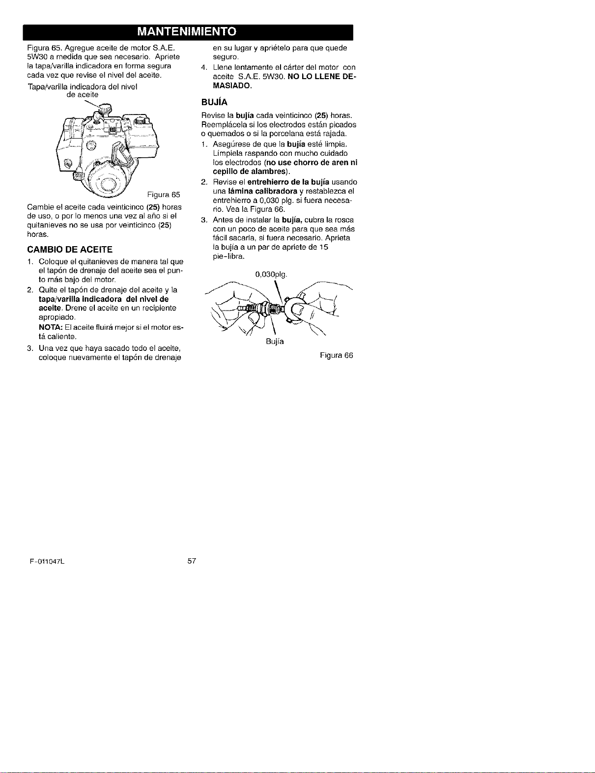
Figura65.AgregueaceitedemotorS.A.E.
5W30amedidaqueseanecesario.Apriete
Iatapa!varillaindicadoraenformasegura
cadavezquereviseelniveldelaceite.
Tapa/varillaindicadoradelnivel
deaceite
Figura65
Cambieelaceitecadaveinticinco(25)horas
deuso,opotIomenosunavezalaSosiel
quitanievesnoseusapotveinticinco(25)
horas.
CAMBIO DE ACEITE
1. Coloque el quitanieves de manera tal que
el tap6n de drenaje del aceite sea ei pun-
to mAs bajo del motor.
2. Quite el tap6n de drenaje del aceite y la
tapa/varilla indicadora del nivel de
aceite. Drene el aceite en un recipiente
apropiado.
NOTA: El aceite fluira mejor si el motor es-
tA caliente.
3. Una vez que haya sacado todo el aceite,
coloque nuevamente el tap6n de drenaje
en su lugar y apri@teto para que quede
seguro.
4. Llene lentamente el carter del motor con
aceite S.A.E. 5W30. NO LO LLENE DE.
MASIADO.
BUJiA
Revise la bujia cada veinticinco (25) horas.
Reemplacela si los electrodos est_n picados
o quemados o si Ia porcelana est_ rajada.
t. Asegt_rese de que la bujia este limpia.
Limpiela raspando con mucho cuidado
ios electrodos (no use ehorro de aren ni
eepillo de alambres).
2. Revise el entrehierro de la bujia usando
una lamina calibradora y restablezca el
entrehierro a 0,030 pig. si fuera necesa-
rio. Vea la Figura 66.
3. Antes de instalar la bujia, cubra la rosca
con un poco de aceite para que sea m_s
facil sacarla, si fuera necesario. Aprieta
Ia bujia a un par de apriete de 15
pie-libra.
0,030pig.
Bujia
Figura 66
F-011047L 57
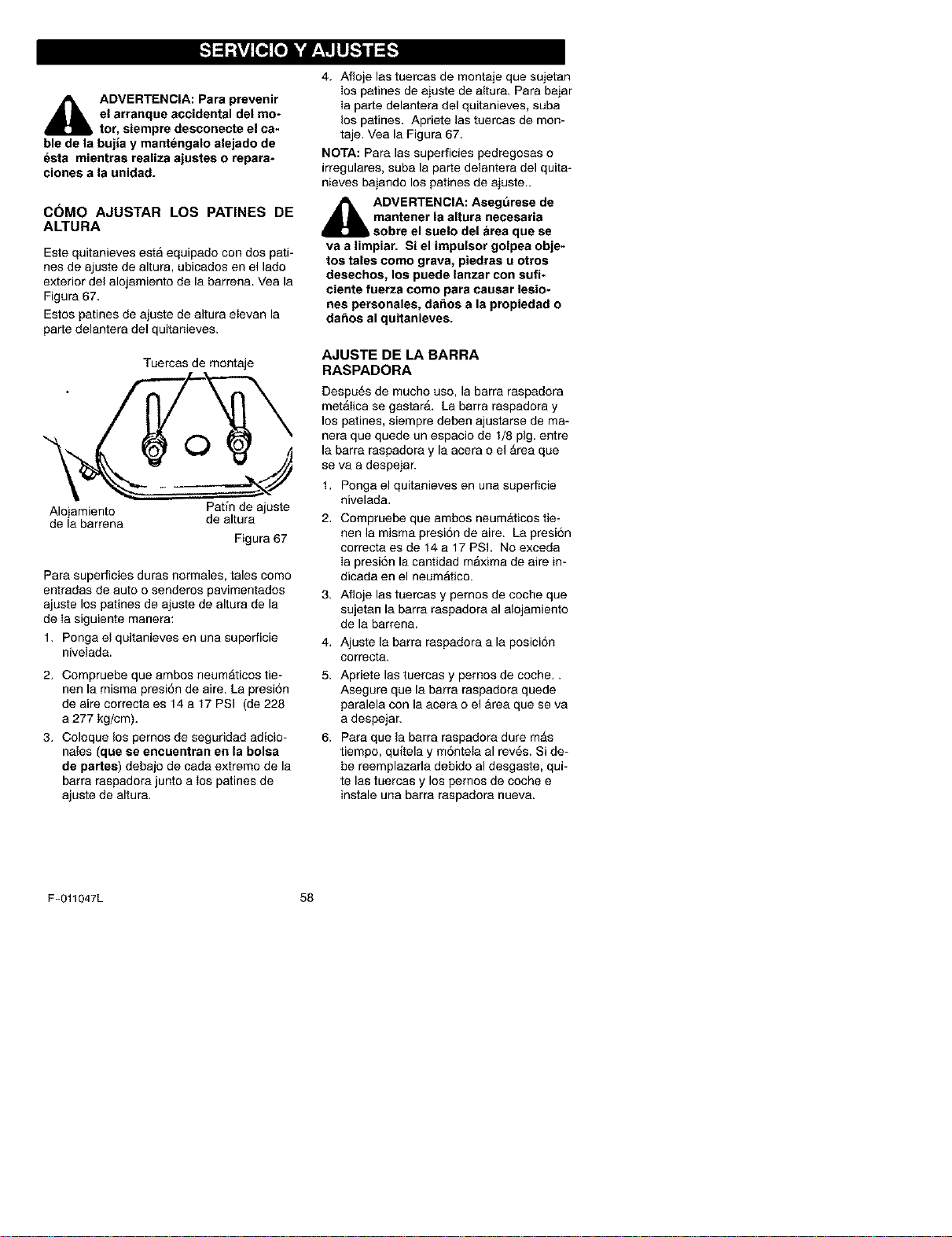
_lb ADVERTENCiA: Para prevenir
el arranque accidental del mo-
tor, siempre desconecte el ca-
ble de la bujia y mantengalo alejado de
esta mientras realiza ajustes o repara-
ciones a la unidad.
C6MO AJUSTAR LOS PATINES DE
ALTURA
Este quitanieves esta equipado con dos pati-
nes de ajuste de altura, ubicados en el lado
exterior del alojamiento de la barren& Vea la
Figura 67.
Estos patines de aiuste de altura eIevan la
parte delantera del quitanieves.
Tuercas de montaje
O
Alojamiento Pafin de ajuste
de la barrena de altura
Figura 67
Para superficies duras normales, tales como
entradas de auto o senderos pavimentados
ajuste los patines de ajuste de altura de la
de Ia siguiente manera:
1. Ponga el quitanieves en una superficie
nivelada.
2. Compruebe que ambos neumAticos tie-
nen la misma presi6n de aire. La presi6n
de aire correcta es 14 a 17 PSI (de 228
a 277 kg/cm).
3. Coloque los pernos de seguridad adicio-
nales (que se encuentran en la bolsa
de partes) debajo de cada extremo de la
barra raspadora junto a los patines de
ajuste de altura.
4. Afloje las tuercas de montaje que sujetan
los patines de ajuste de altura. Para bajar
Ia parte delantera del quitanieves, suba
los patines. Apriete las tuercas de mon-
taje. Vea la Figura 67.
NOTA: Para las superficies pedregosas o
irregulares, suba la parte delantera del quita-
nieves bajando los patines de ajuste..
_1= DVERTENCIA: Asegurese de
mantener la altura necesaria
sobre el suelo del Area que se
va a limpiar. Si el impulsor golpea obje-
tos tales como grava, piedras u otros
desechos, los puede lanzar con sufi-
ciente fuerza como para causar lesio-
nes personales, da_os a la propiedad o
dafms al quitanieves.
AJUSTEDELABARRA
RASPADORA
Despu6s de mucho uso, la barra raspadora
met_Iica se gastar& La barra raspadora y
los patines, siempre deben ajustarse de ma-
nera que quede un espacio de 1/8 pig. entre
la barra raspadora y la acera o el Area que
se va a despejar.
1. Ponga el quitanieves en una superficie
nivelada.
Compruebe que ambos neumAticos tie-
nen la misma presi6n de aire. La presi6n
correcta es de 14 a 17 PSI. No exceda
Ia presi6n la cantidad maxima de aire in-
dicada en el neumAtico.
3. Afloje las tuercas y pernos de coche que
sujetan la barra raspadora al alojamiento
de la barrena.
4. Ajuste la barra raspadora a la posici6n
oorreota.
5. Apriete las tuercas y pernos de coche..
Asegure que la barra raspadora quede
paralela con la acera o el Area que se va
a despejar.
6. Para que la barra raspadora dure mAs
tiempo, quflela y m6ntela al rev6s. Si de-
be reemplazarla debido al desgaste, qui-
te las tuercas y los pemos de coche e
instale una barra raspadora nueva.
F-011047L 58
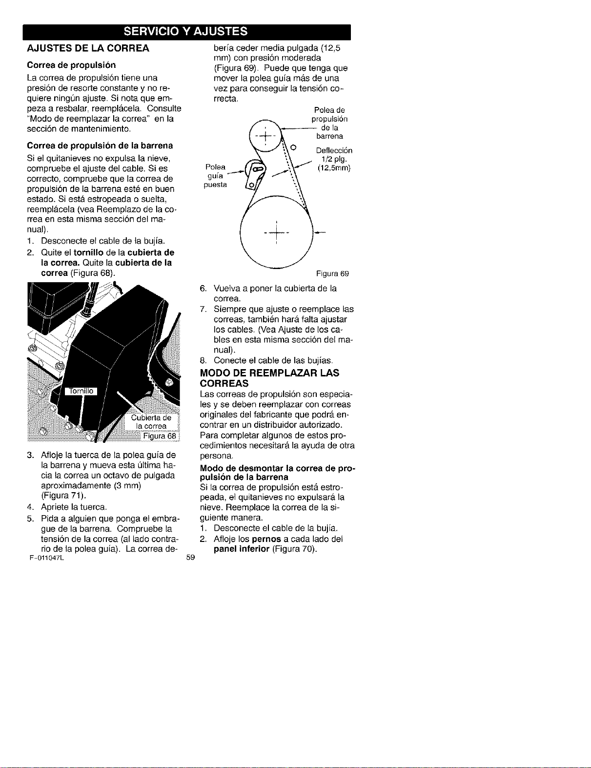
AJUSTES DE LA CORREA
Correa de propulsion
La correa de propulsi6n tiene una
presi6n de resorte constante y no re-
quiere ningQn ajuste. Si nora que em-
peza a resbalar, reempl&cela. Consulte
"Modo de reemplazar la correa" en la
secci6n de mantenimiento.
Correa de propulsion de la barrena
Si el quitanieves no expulsa la nieve,
compruebe el ajuste del cable. Si es
correcto, compruebe que la correa de
propulsi6n de la barrena este en buen
estado. Siesta estropeada o suelta,
reempl_.cela (vea Reemplazo de la co-
rrea en esta misma secci6n del ma-
nual).
1. Desconecte el cable de la bujia.
2. Quite el tornillo de la cubierta de
la correa. Quite la cubierta de la
correa (Figura 68).
Figura 68 _
3. Afloje la tuerca de la polea guia de
la barrena y mueva esta Qltima ha-
cia la correa un octavo de pulgada
aproximadamente (3 mm)
(Figura 71).
4. Apriete latuerca.
5. Pida a alguien que ponga el embra-
gue de la barrena. Compruebe la
tensi6n de la correa (al lado contra-
rio de la polea guia). La correa de-
F-011047L
59
beria coder media pulgada (12,5
mm) con presi6n moderada
(Figura 69). Puede que tenga que
mover la polea guia mas de una
vez para conseguir la tensi6n co-
rrecta.
Poleade
-- barrena
lll2e;tg(_n
Polea (_ "\/ (12,5turn)
0
Figura 69
6. Vuelva a poner la cubierta de la
correa.
7. Siempre que ajuste o reemplace las
correas, tambien hara falta ajustar
los cables. (Vea Ajuste de los ca-
bles en esta misma secci6n del ma-
nual).
8. Conecte el cable de las bujias.
MODO DE REEMPLAZAR LAS
CORREAS
Las correas de propulsi6n son especia-
les y se deben reemplazar con correas
originales del fabricante que podr& en-
contrar en un distribuidor autorizado.
Para completar algunos de estos pro-
cedimientos necesitar& la ayuda de otra
persona.
Modo de desmontar la correa de pro-
pulsion de la barrena
Si la correa de propulsi6n est,. estro-
peada, el quitanieves no expulsar_, la
nieve. Reemplace la correa de la si-
guiente manera.
1. Desconecte el cable de la bujia.
2. Afloje los pernos a cada lado del
panel inferior (Figura 70).
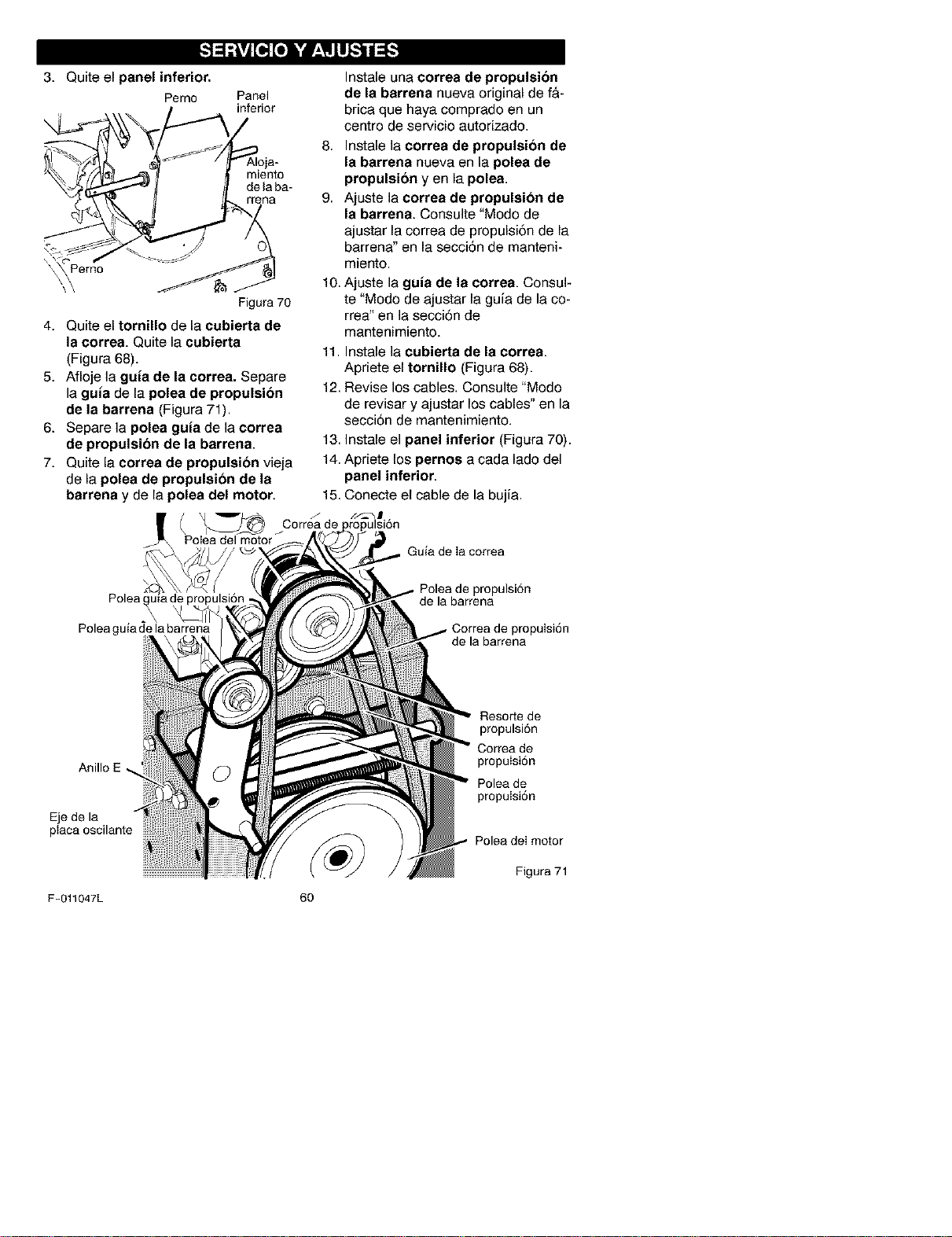
3. Quiteelpanel inferior.
Pemo
Panel
inferior
Instale una correa de propulsion
de la barrena nueva original de f&-
brica que haya comprado en un
centro de servicio autorizado.
miento
de la ba-
rrena
Figura 70
4. Quite el tornillo de la cubierta de
la correa. Quite la cubierta
(Figura 68).
5. Afloje la guia de la correa. Separe
la gula de la polea de propulsion
de la barrena (Figura 71).
6. Separe la polea guia de la correa
de propulsion de la barrena.
7. Quite la correa de propulsion vieja
de la polea de propulsion de la
barrena y de la polea del motor.
8. Instale la correa de propulsion de
la barrena nueva en la polea de
propulsion yen la polea.
9. Ajuste la eorrea de propulsion de
la barrena. Consulte "Modo de
ajustar la correa de propulsiSn de la
barrena" en la secci6n de manteni-
miento.
10. Ajuste la gula de la correa. Consul-
te "Modo de ajustar la guia de la co-
rrea" en la secciSn de
mantenimiento.
11. Instale la eubierta de la eorrea.
Apriete el tornillo (Figura 68).
12. Revise los cables. Consulte "Modo
de revisar y ajustar los cables" en la
secci6n de mantenimiento.
13. Instale el panel inferior (Figura 70).
14. Apriete los pernos a cada lade del
panel inferior.
15. Conecte el cable de la bujia.
( X_ iCorre_d e
Polea del motor
Guia de Ia correa
Polea
Poleaguiade la barrena
propulsi6n
de la barrena
propuisi6n
de la barrena
Anillo
Eje de la
ptaca oscilante
Resorte de
propulsi6n
Correa de
propulsi6n
Polea de
propulsi6n
Polea deI motor
Figura 71
F-O11047L 60
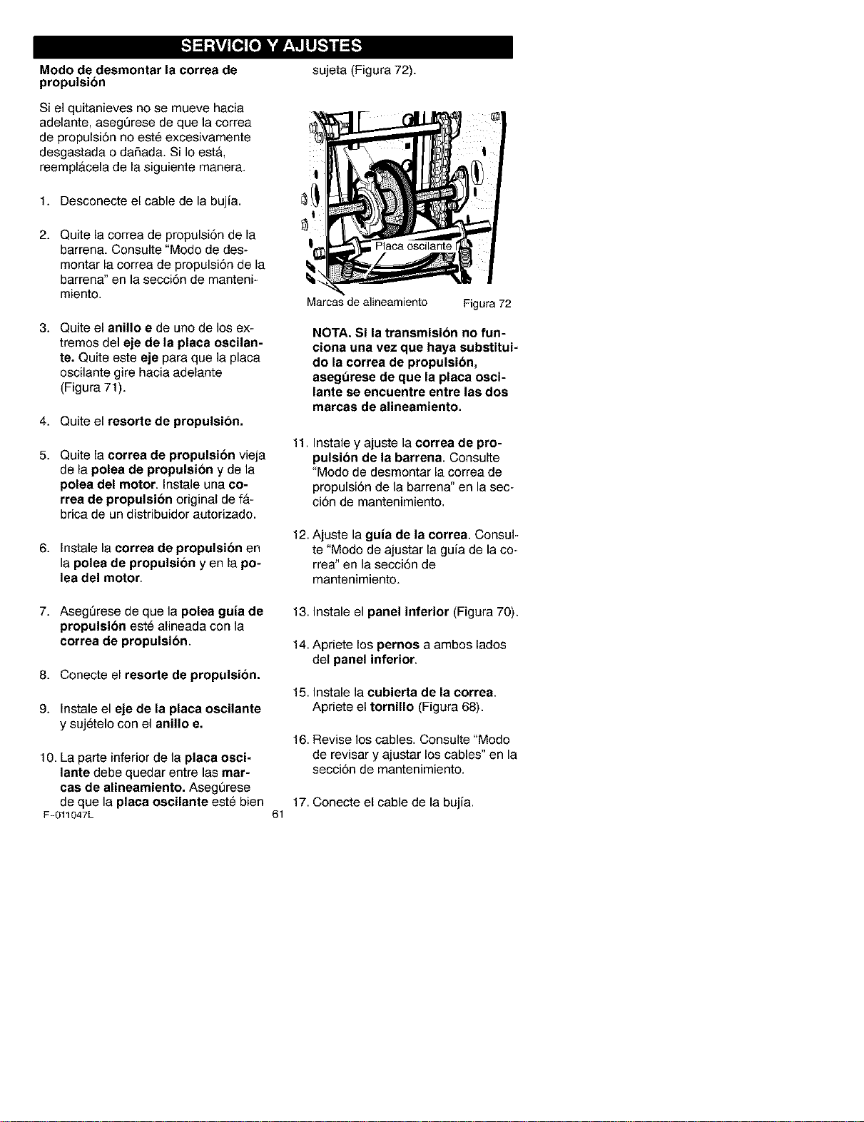
Modo de desmontar la correa de
propulsion
Si el quitanieves no se mueve hacia
adelante, aseg_rese de que la correa
de propulsi6n no est@excesivamente
desgastada o dafiada. Si Io est&,
reempl&cela de la siguiente manera.
1. Desconecte el cable de la bujia.
2. Quite la correa de propulsi6n de la
barrena. Consulte "Modo de des-
montar la correa de propulsi6n de la
barrena" en la secci6n de manteni-
miento.
3. Quite el anillo e de uno de los ex-
tremos del eje de la placa oscilan-
te. Quite este eje para que la placa
oscilante gire hacia adelante
(Figura 71).
4. Quite el resorte de propulsion,
5. Quite la correa de propulsion vieja
de la polea de propulsion y de la
polea del motor. Instale una co-
rrea de propulsion original de f&-
brica de un distribuidor autorizado.
6. Instale la correa de propulsion en
la polea de propulsion yen la po-
lea del motor.
sujeta (Figura 72).
11.
Marcas de alineamiento Figura 72
NOTA. Si la transmision no fun-
ciona una vez que haya substitui-
do la correa de propulsibn,
asegt_rese de que la placa osci-
lante se encuentre entre las dos
marcas de alineamiento.
Instale y ajuste la correa de pro-
pulaion de la barrena. Consulte
"Modo de desmontar ia correa de
propulsi6n de la barrena" en la sec-
ci6n de mantenimiento.
12. Ajuste la guia de la correa. Consul-
te "Modo de ajustar la guia de la co-
rrea" en la secci6n de
mantenimiento.
7. Aseg_rese de que la polea guia de
propulsion est_ alineada con la
correa de propulsion.
8. Conecte el resorte de propulsion.
9. Instale el eje de la placa oscilante
y suj_telo con el anillo e.
10. La parte inferior de la placa osci-
lante debe quedar entre las mar-
cas de alineamiento. AsegQrese
de que la placa oscilante este bien
F-011047L
17.
61
13. Instale el panel inferior (Figura 70).
14. Apriete los pernos a ambos lados
del panel inferior.
15. Instale la cubierta de la correa.
Apriete el tornillo (Figura 68).
16. Revise los cables. Consulte "Modo
de revisar y ajustar los cables" en la
secci6n de mantenimiento.
Conecte el cable de la bujia.
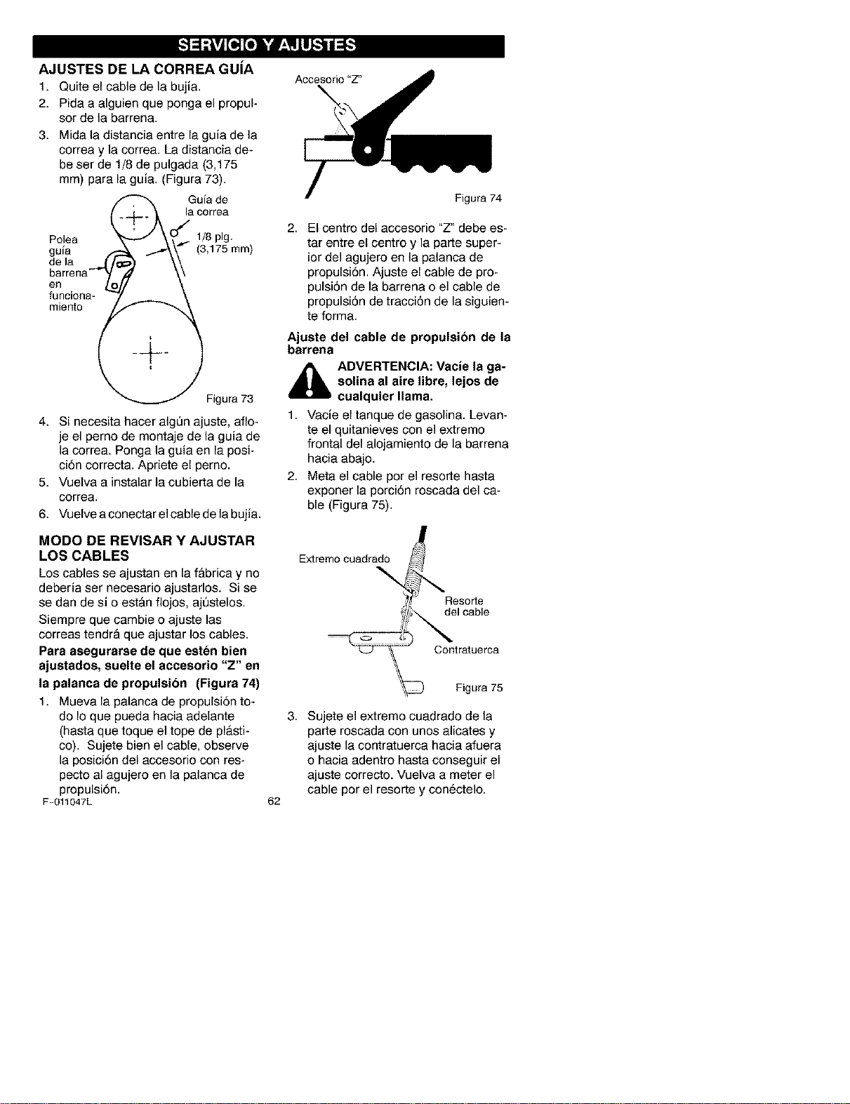
AJUSTES DE LA CORREA GUiA
1. Quite el cable de la bujia.
2. Pida a alguien que ponga el propul-
sor de la barrena.
3. Mida la distancia entre la guia de la
correa y la correa. La distancia de-
be ser de 1/8 de pulgada (3,175
mm) para la guia. (Figura 73).
Polea
guia
de la
barrena
en
funciona-
miento
( 1/o0,0
_-- _ (3,175ram)
)
Figura73
4. Si necesita hacer algOn ajuste, aflo-
je el perno de montaje de la guia de
la correa. Ponga la guia en la posi-
ci6n correcta. Apriete el perno.
5. Vuelva a instalar la cubierta de la
correa.
6. Vuelve a conectar el cable de la bujia.
Accesorio "Z"
Figura 74
2. El centro del accesorio "Z" debe es-
tar entre el centre y la parte super-
ior del agujero en la palanca de
propulsi6n. Ajuste el cable de pro-
pulsiSn de la barrena o el cable de
propulsiSn de tracciSn de la siguien-
te forma.
Ajuste del cable de propulsion de la
barrena
_IL DVERTENClA: Vacle la ga-
solina al aire libre, lejos de
cualquier llama.
1. Vacie el tanque de gasolina. Levan-
te el quitanieves con el extreme
frontal del alojamiento de la barrena
hacia abajo.
2. Meta el cable por el resorte hasta
exponer la porci6n roscada del ca-
ble (Figura 75).
MODO DE REVISAR Y AJUSTAR
LOS CABLES Extremocuadrado
LOScables se ajustan en la f&brica y no
deberia ser necesario ajustarlos. Si se
se dan de si o est&n flojos, aj0stelos.
Siempre que cambie o ajuste las
correas tendr& que ajustar los cables.
Para aaegurarse de que eeten bien
ajustadoa, suelte el accesorio "Z" en
la palanca de propulsion (Figura 74)
1. Mueva la palanca de propulsi6n to-
do Io que pueda hacia adelante
(hasta que toque el tope de pl&sti-
co). Sujete bien el cable, observe
la posici6n del accesorio con res_
pecto al agujero en la palanca de
propulsi6n.
F-011047L 62
Resorte
del cable
Contratuerca
Figura 75
3. Sujete el extremo cuadrado de la
parte roscada con unos alicates y
ajuste la contratuerca hacia afuera
o hacia adentro hasta conseguir el
ajuste correcto. Vuelva a meter el
cable por el resorte y con@ctelo.
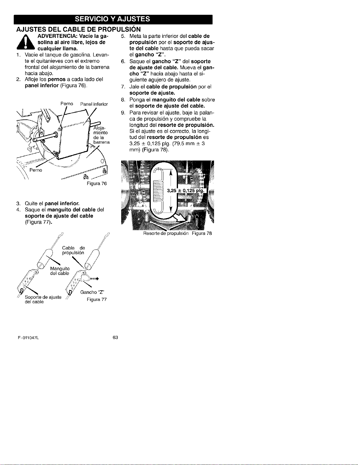
AJUSTES DEL CABLE DE PROPULSION
_lb ADVERTENCIA: Vacie la ga- 5. Meta la parte inferior del cable de
solina al aire libre, lejos de
cualquier llama.
1. Vacie el tanque de gasolina. Levan-
te el quitanieves con el extremo 6.
frontal del alojamiento de la barrena
hacia abajo.
2. Afloje los pernoe a cada lado del
panel inferior (Figura 76).
propulsion por el soporte de ajus-
J
Pemo
\\
Perno Panelinferior
Figura76
7,
8.
9.
te del cable hasta que pueda sacar
el gancho "Z".
Saque el gancho "Z" del soporte
de ajuste del cable. Mueva el gan-
cho "Z" hacia abajo hasta el si-
guiente agujero de ajuste.
Jale el cable de propulsion por el
soporte de ajuste.
Ponga el manguito del cable sobre
el soporte de ajuste del cable.
Para revisar el ajuste, baje la palan-
ca de propulsi6n y compruebe la
Iongitud del resorte de propulsion.
Si el ajuste es el correcto, la Iongi-
tud del resorte de propulsion es
3,25 _+0,125 pig. (79,5 mm _+3
mm) (Figura 78).
3. Quite el panel inferior.
4. Saque el manguito del cable del
soporte de ajuste del cable
(Figura 77).
Soporte deajuste /_ G, nccho"Z"
del cable Figura77
Resorte de propulsi6n Figura 78
F-011047L 63
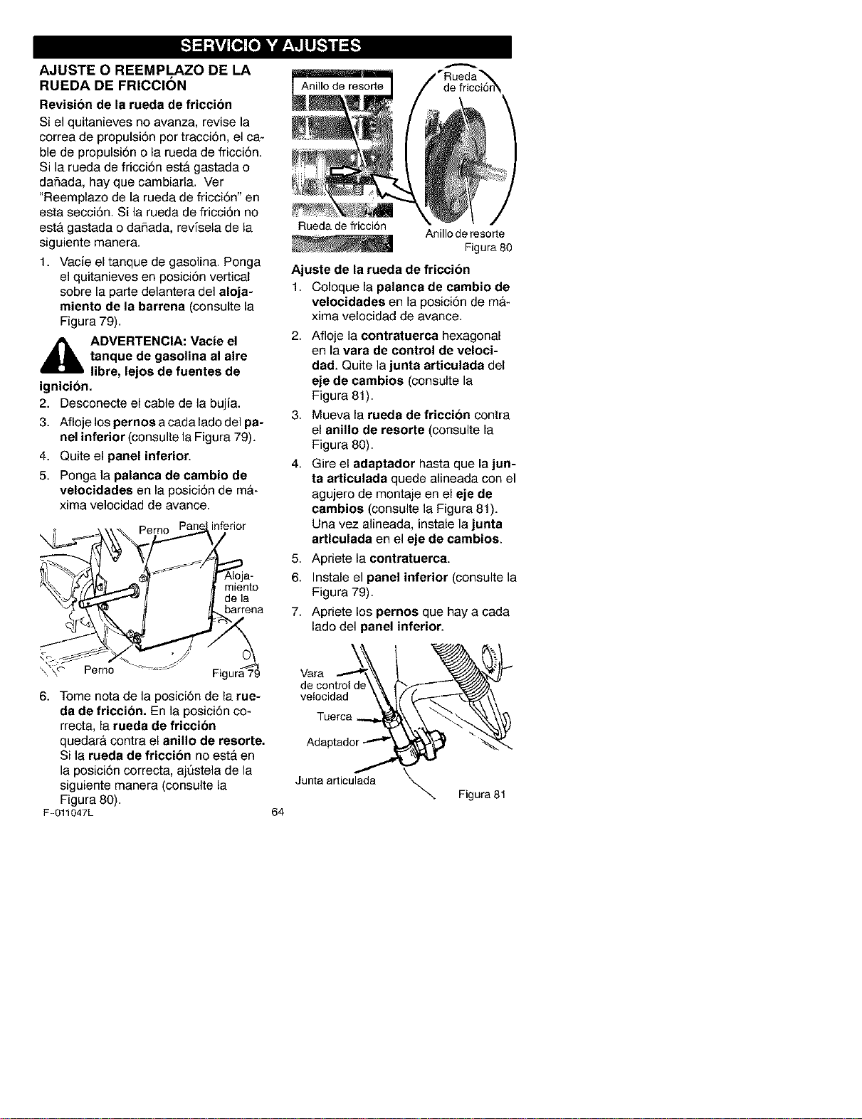
AJUSTE O REEMPLAZO DE LA
RUEDA DE FRICCION
Revision de la rueda de friccion
Si el quitanieves no avanza, revise la
correa de propulsi6n per tracci6n, el ca-
ble de propulsi6n o la rueda de fricci6n.
Si la rueda de fricci6n est& gastada o
daSada, hay que cambiarla. Ver
"Reemplazo de la rueda de fricci6n" en
esta secci6n. Si la rueda de fricci6n no
esta gastada o dafiada, revfsela de la
siguiente manera.
1. Vacie el tanque de gasolina. Ponga
el quitanieves en posici6n vertical
sobre la parte delantera del aloja-
miento de la barrena (consulte la
Figura 79).
i_ ADVERTENCIA: Vacte el
tanque de gasolina al aire
libre, lejos de fuentes de
ignicion.
2. Desconecte el cable de la bujia.
3. Afloje los pernos acada lado del pa-
nel inferior (consulte la Figura 79).
4. Quite el panel inferior.
5. Ponga la palanca de cambio de
velocidades en la posici6n de ma-
xima velocidad de avance.
Perno inferior
miento
de la
barrena
\\'\c- Perno Figura79
Anillo de resorte de fricci6n_
Rueda de fricci6n
Anillo de resorte
Figura 80
Ajuste de la rueda de friccion
1. Coloque la palanca de cambio de
velocidades en la posici6n de ma-
xima velocidad de avance.
2. Afloje la contratuerca hexagonal
en la vara de control de veloci-
dad. Quite la junta articulada del
eje de cambios (consulte la
Figura 81).
3. Mueva la rueda de friccion contra
el anillo de resorte (consulte la
Figura 80).
4. Gire el adaptador hasta que la jun-
ta articulada quede alineada con el
agujero de montaje en el eje de
cambioe (consulte la Figura 81).
Una vez alineada, instale la junta
articulada en el eje de cambios.
5. Apriete la contratuerca.
6. Instale el panel inferior (consulte la
Figura 79).
7. Apriete los pernos que hay a cada
lado del panel inferior.
Vara
de control de
vetocidad
6. Tome nota de la posici6n de la rue-
da de friccion. En la posici6n co- Tuerca
rrecta, la rueda de friccion
quedar& contra el anillo de reeorte.
Si la rueda de friccion no est& en
la posici6n correcta, aj_stela de la
siguiente manera (consulte la Junta articulada
Figura 80).
F-011047L 64
Figura 81
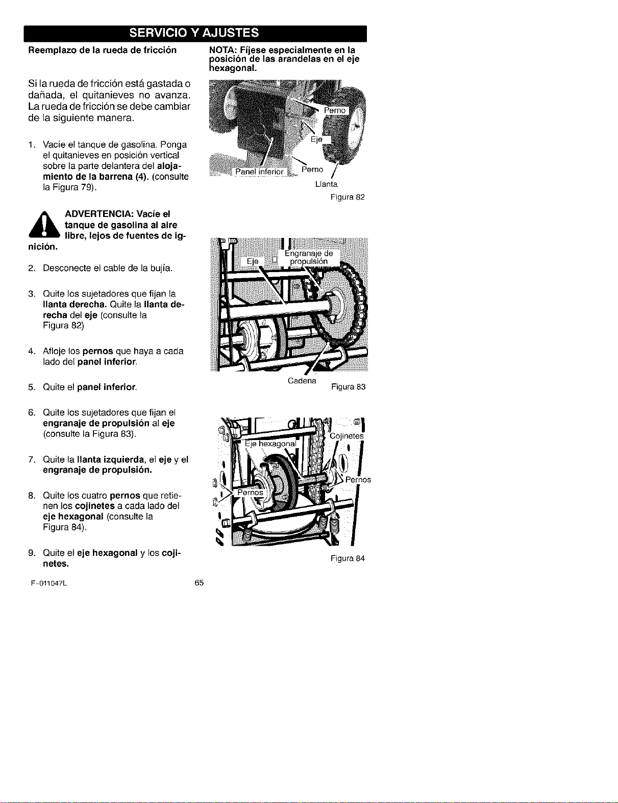
Reemplazo de la rueda de friccion
Si la rueda de fricci6n est& gastada o
dafiada, el quitanieves no avanza.
La rueda de fricci6n se debe cambiar
de la siguiente manera.
1. Vacie el tanque de gasolina. Ponga
el quitanieves en posici6n vertical
sobre la parte delantera del aloja-
miento de la barrena (4). (consulte
la Figura 79).
NOTA: Fijese especialmente en la
posicion de las arandelas en el eje
hexagonal.
Pemo
nicion.
ADVERTENCIA: Vacte el
tanque de gasolina al aire
libre, lejos de fuentes de ig-
2. Desconecte el cable de la bujia.
3. Quite los sujetadores que fijan la
Ilanta derecha. Quite la Ilanta de-
recha del eje (consulte la
Figura 82)
4. Afloje los pernos que haya a cada
lado del panel inferior.
5. Quite el panel inferior.
6. Quite los sujetadores que fijan el
engranaje de propulsion al eje
(consulte la Figura 83).
7. Quite la Ilanta izquierda, el eje y el
engranaje de propulsion.
8. Quite los cuatro pernos que retie-
nen los cojinetes a cada lado del
eje hexagonal (consulte la
Figura 84).
9. Quite el eje hexagonal y los coji-
netes.
Llanta
Figura 82
Cadena
Figura 83
netes
_Pemos
Figura 84
F-O11047L 65
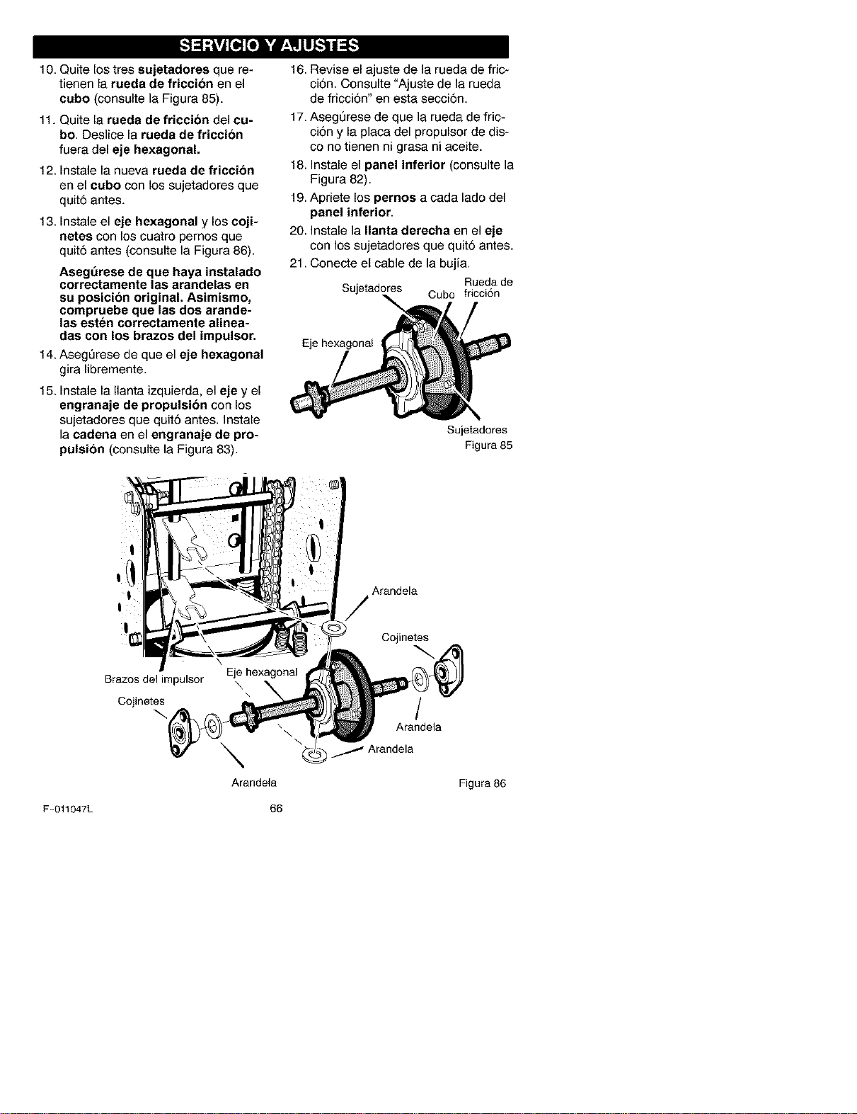
10. Quite los tres sujetadores que re-
tienen la rueda de friccion en el
cubo (consulte la Figura 85).
11. Quite la rueda de friccion del cu-
bo. Deslice la rueda de friccion
fuera del eje hexagonal.
12. Instale la nueva rueda de friecion
en el cubo con los sujetadores que
quit6 antes.
13. Instale el eje hexagonal y los coji-
netes con los cuatro pernos que
quit6 antes (consulte la Figura 86).
Asegt_rese de que haya instalado
correctamente las arandelas en
su posicion original. Asimismo,
compruebe que las dos arande-
las esten correctamente alinea-
das con los brazos del impulsor.
t 4. Aseg_rese de que el eje hexagonal
gira libremente.
15. Instale la Ilanta izquierda, el eje y el
engranaje de propulsion con los
sujetadores que quit6 antes. Instale
la cadena en el engranaje de pro-
pulsion (consulte la Figura 83).
16.
Revise el ajuste de la rueda de fric-
ci6n. Consulte "Ajuste de la rueda
de fricci6n" en esta secci6n.
17. AsegQrese de que la rueda de fric-
ci6n y la placa del propulsor de dis-
co no tienen ni grasa ni aceite.
18. Instale el panel inferior (consulte la
Figura 82).
19. Apriete los pernos a cada lado del
panel inferior.
20. Instale la Ilanta derecha en el eje
con los sujetadores que quit6 antes.
21. Conecte el cable de la bujia.
Rueda de
Sujetadores Cubo fricci6n
Eje hexagonal
Sujetadores
Figura 85
Arandela
Brazos delimpulsor
Cojinetes
\
Arandela
Cojinetes
Arandela
Figura 86
F-011047L 66
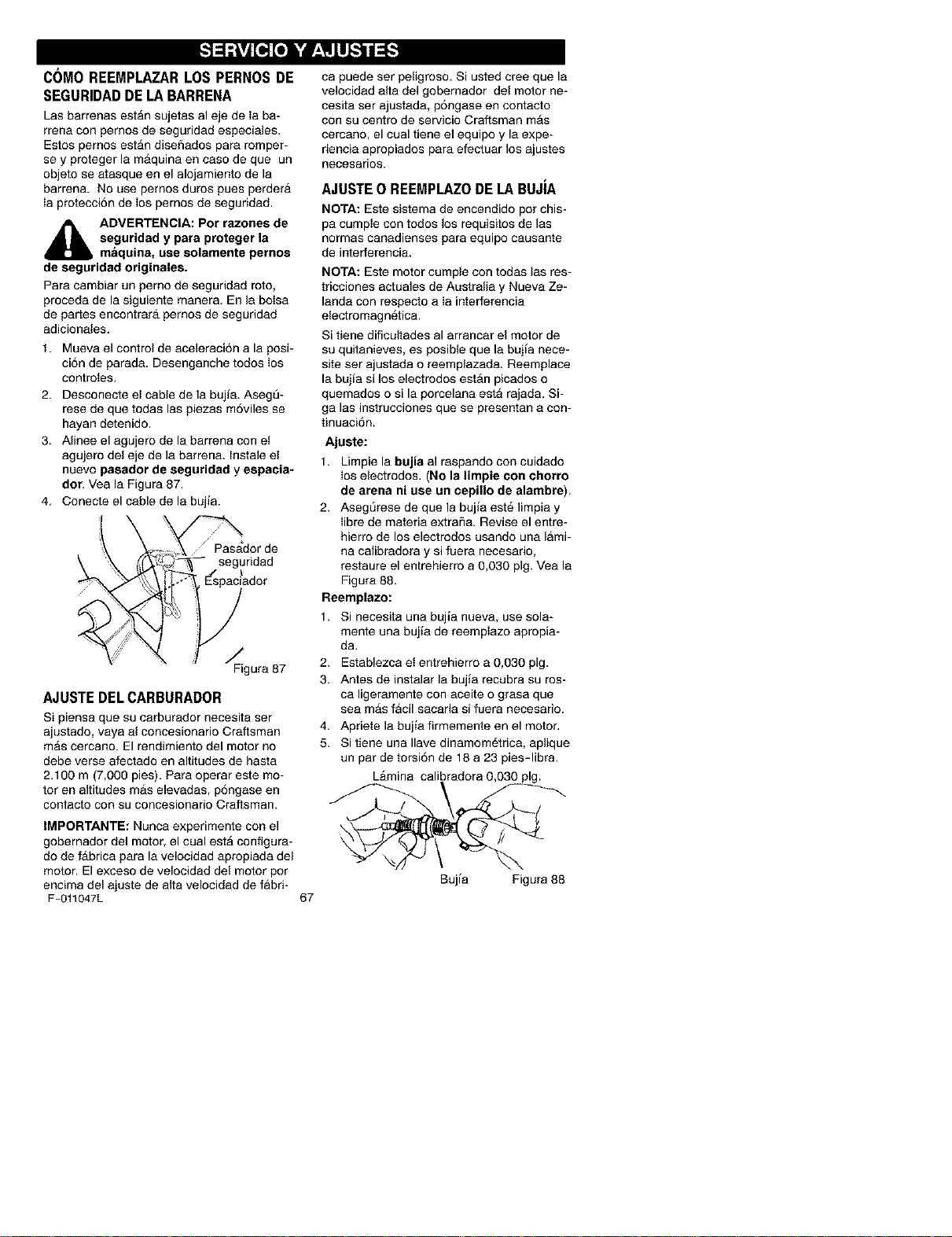
C()MO REEMPLAZARLOSPERNOSDE
SEGURIDADDELABARRENA
Las barrenas estAn sujetas al eje de Ia ba-
rrena con pernos de seguridad especiales.
Estos pernos estAn diseSados para romper-
se y proteger la mAquina en caso de que un
objeto se atasque en el alojamiento de la
barren& No use pemos duros pues perdera
Ia protecci6n de los pemos de seguridad.
_IL DVERTENCIA: Por razones de
seguridad y para proteger la
maquina, use solamente pernos
de seguridad originales.
Para cambiar un perno de seguridad roto,
proceda de la siguiente manera. En la bolsa
de partes encontrarA pernos de seguddad
adicionales.
1. Mueva el control de aceleraci6n a la posi-
ci6n de parada. Desenganche todos los
controtes.
2. Desconecte el cable de la bujia. Asegt3-
rese de que todas las piezas m6viles se
hayan detenido.
3. Alinee el agujero de la barrena con et
agujero del eje de la barrena. Instale el
nuevo pasador de seguridad y espacia-
dor. Vea la Figura 87.
4. Conecte el cable de la bujla.
'_dor de
_ _L" --.segiridad
i°, Espaciador
/
Figura 87
AJUSTEDELCARBURADOR
Si piensa que su carburador necesita ser
ajustado, vaya al concesionario Craftsman
mAs cercano. El rendimiento del motor no
debe verse afectado en altitudes de hasta
2.100 m (7,000 pies). Para operar este mo-
tor en altitudes mAs elevadas, p6ngase en
oontacto con su concesionario Craftsman.
IMPORTANTE: Nunca experimente con el
gobernador del motor, el cual estA configura-
do de fAbrica para la velocidad apropiada del
motor. El exceso de velocidad del motor por
encima del ajuste de alta velocidad de fabri-
F-011047L
ca puede ser peligroso. Si usted cree que la
velocidad alta del gobernador del motor ne-
cesita set ajustada, p6ngase en contacto
con su centro de servicio Craftsman mAs
cercano, el cual tiene el equipo y la expe-
riencia apropiados para efectuar los ajustes
necesarios.
AJUSTE0 REEMPLAZODELA BUJiA
NOTA: Este sistema de encendido por chis-
pa cumpte con todos los requisitos de las
normas canadienses para equipo causante
de interferencia.
NOTA: Este motor cumple con todas las res-
tricciones actuales de Australia y Nueva Ze-
landa con respecto a Ia interferencia
electromagnetica.
Si tiene dificultades al arrancar el motor de
su quitanieves, es posible que la bujia nece-
site set ajustada o reemplazada. Reemplace
la bujia si los electrodos estAn picados o
quemados o si la porcelana esta rajada. Si-
ga las instrucciones que se presentan a con-
tinuaci6n.
Ajuste:
1. Limpie la bujia al raspando con cuidado
los electredos. (No la lirnpie con chorro
de arena ni use un cepillo de alambre).
2. Asegt_rese de que la bujia est_ limpia y
Iibre de materia extra_a. Revise el entre-
hierro de los electrodos usando una lami-
na calibradora y si fuera necesario,
restaure el entrehierro a 0,030 pig. Vea la
Figura 88.
Reemplazo:
1. Si necesita una buj_a nueva, use sola-
mente una bujia de reemptazo apropia-
da.
2. Establezca et entrehierro a 0,030 pig.
3. Antes de instalar la bujia recubra su ros-
ca ligeramente con aceite o grasa que
sea mAs f&cil sacarla si fuera necesario.
4. Apriete la bujia firmemente en el motor.
5. Si tiene una Ilave dinamom6trica, aplique
un par de torsi6n de 18 a 23 pies-libra.
LAmina calibradora 0,030
67
Bujia Figura 88
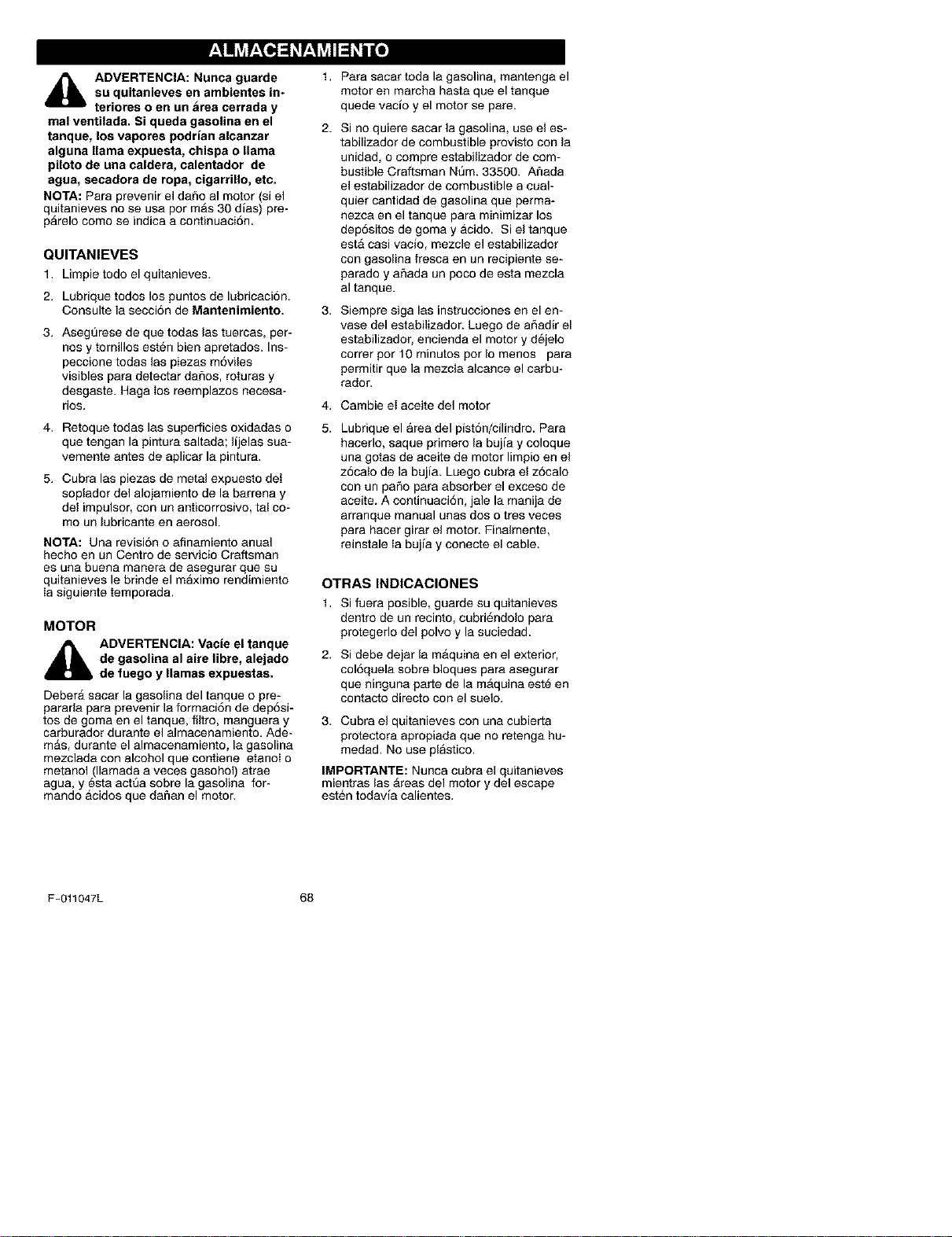
M ! _vjr;Te]=1_r;__vjII=1_ili[o]
_1= DVERTENCIA: Nunca guarde
su quitanieves en ambientes in-
teriores o en an area cerrada y
real ventilada. Si queda gasolina en el
tanque, los vapores podrian alcanzar
alguna llama expuesta, chispa o llama
piloto de una caldera, calentador de
agua, secadora de ropa, cigarrillo, etc.
NOTA: Para prevenir el dafio al motor (si el
quitanieves no se usa par mAs 30 dims) pre-
pArelo como se indica a contlnuaci6n.
QUlTANIEVES
1. Limpie todo el quitanieves.
2. Lubrique todos los puntos de lubricaci6n.
Consulte la secci6n de Mantenimiento.
3. AsegSrese de que todas las tuercas, per-
nosy tornillos esten bien apretados. Ins-
peccione todas las piezas m6viles
visibles para detectar dafios, roturas y
desgaste. Haga los reemplazos necesa-
rios.
4. Retoque todas las superficies oxidadas o
que tengan la pintura saltada; lijelas sua-
vemente antes de aplicar la pintura.
5. Cubra las piezas de metal expuesto dei
soplador del alojamiento de la barrena y
del impulsor, con un anticorrosivo, tal co-
mo un lubricante en aerosol.
NOTA: Una revisi6n o afinamiento anual
hecho en un Centre de servicio Craftsman
es una buena manera de asegurar que su
quitanieves le brinde el maximo rendimiento
Ia siguiente temporada.
MOTOR
ADVERTENCIA: VacJe el tanque
de gasolina al airs libre, alejado
de faego y llamas expuestas.
Deber_ sacar la gasolina del tanque o pre-
pararla para prevenir la formaci6n de dep6si-
tos de goma en el tanque, filtro, manguera y
carburador durante el almacenamiento. Ade-
m_s, durante el almacenamiento, la gasolina
mezclada con alcohol que contiene etanoi o
metanol (llamada a veces gasohol) atrae
agua, y @staactt3a sobre la gasolina for-
mando acidos que dafian el motor.
t,
2.
Para sacar toda la gasolina, mantenga el
motor en marcha hasta que el tanque
quede vacio y el motor se pare.
Si no quiere sacar la gasolina, use el es-
tabilizador de combustible provisto con la
unidad, o compre estabilizador de com-
bustible Craftsman Nt_m. 33500. Afiada
el estabilizador de combustible a cual-
quier cantidad de gasolina que perma-
nezca en el tanque para minimizar los
dep6sitos de goma y acido. Si el tanque
est_ casi vacio, mezcle el estabilizador
con gasolina fresca en un recipiente se-
parado y afiada un poco de esta mezcla
al tanque.
Siempre siga las instrucciones en el en-
vase del estabilizador. Luego de afiadir el
estabilizador, encienda el motor y dejelo
correr por 10 minutos pot Io menos para
permitir que la mezcla alcance el carbu-
rador.
Cambie ei aceite del motor
Lubrique el area del pist6n/cilindro. Para
hacerlo, saque primero la bujia y coloque
una gotas de aceite de motor limpio en el
z6calo de la bujia. Luego cubra el z6calo
con un patio para absorber el exceso de
aceite. A continuaci6n, jale la manija de
arranque manual unas dos o tres yeses
para hacer girar el motor. Finalmente,
reinstale Ia bujia y conecte el cable.
OTRAS INDICACIONES
t. Si fuera posible, guarde su quitanieves
dentro de un recinto, cubri6ndolo para
protegerlo del polvo y la suciedad.
2. Si debe dejar la m_quina en el exterior,
col6quela sobre bloques para asegurar
que ninguna parte de la m_quina este en
contacto directo con el suelo.
3. Cubra el quitanieves con una cubierta
protectora apropiada que no retenga hu-
medad. No use plastico.
IMPORTANTE: Nunca cubra el quitanieves
mientras las _reas del motor y del escape
esten todav{a calientes.
F-011047L 68
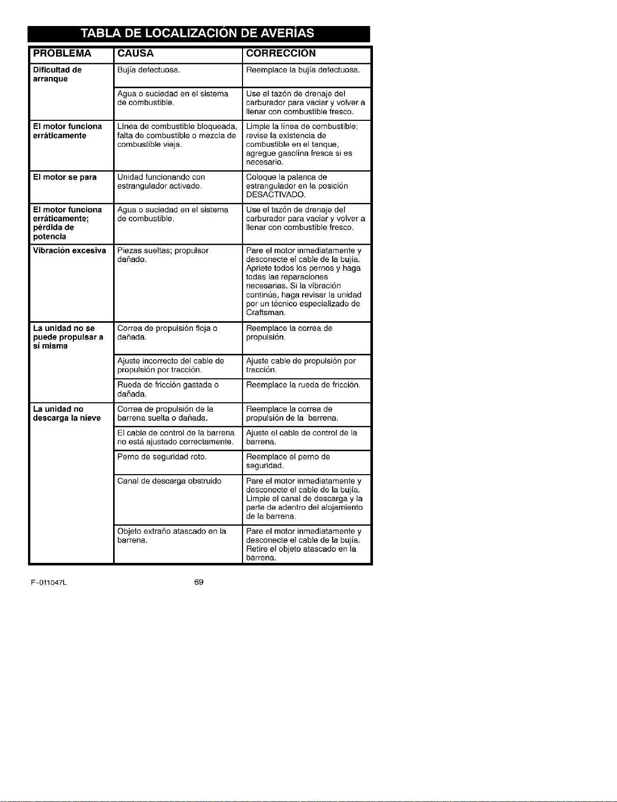
Inf_*1:]W_*ll I[olo _*1ml
PROBLEMA
Dificultadde
arranque
CAUSA CORRECCION
Buj_adefectuosa. Reernplace labujia defectuosa.
Agua o suciedad en et sistema Use el taz6n de drenaje del
de combustible, carburador para vaciar y velvet a
Ilenar con combustible fresco.
El motor funciona Linea de combustible bloqueada, Limpie la Iinea de combustible;
err_tioamente falta de combustible o mezcla de revise la existencia de
combustible vieja, combustible en el tanque,
agregue gasolina fresca si es
neoesario.
El motor se para Unidad funcionando con Coloque la palanca de
estrangulador activado, estrangulador en la posici6n
DESACTIVADO.
El motor funoiona Agua o suciedad en ei sistema Use el taz6n de drenaje del
erraticamente; de combustible, carburador para vaciar y volver a
)erdida de Ilenar con combustible fresco.
)otenoia
Vibracion excesiva Piezas suettas; propulsor Pare el motor inmediatamente y
daSado, desconecte el cable de la bujia.
Apriete todos los pemos y haga
todas las reparaciones
necesarias. Si la vibraci6n
continEa, haga revisar la unidad
por un tecnico especializado de
Craftsman.
La unidad no se Correa de propulsi6n floja o Reemplace la correa de
puede propulsar a daSada, propulsi6n.
si misma
Ajuste incorrecto del cable de Ajuste cable de propulsi6n por
propulsi6n por tracci6n, tracci6n.
Rueda de fricci6n gastada o Reemplace la rueda de fricci6n.
da_ada.
La unidad no Correa de propulsi6n de la Reemplace la correa de
descarga la nieve barrena suelta o daSada, propulsi6n de la barrena.
El cable de control de Ia barrena Ajuste el cable de control de la
no est_ ajustado correctamente, barrena.
Perno de seguridad roto. Reemplace el perno de
seguridad.
Canal de descarga obstruido Pare el motor inmediatamente y
desconecte el cable de la bujJa.
Limpie el canal de descarga y la
parte de adentro del alojamiento
de la barrena.
Objeto extraflo atascado en la
barrena.
Pare el motor inmediatamente y
desconecte el cable de la bujia
Retire el objeto atascado en la
barrena.
F-011047L 69
SEARS, ROEBUCK AND CO.
Garantia limitada de cumplimiento con el Sistema Federal
de control de emisiones y con el sistema de control de
emisiones del Estado de California
Motores pequehos no aptos para carretera (off-road)
CONTROL DE EMISIONES DE
CALIFORNIA Y DE LA AGENCIA DE
PROTECCI(_N AMBIENTAL (EPA) DE
E.U.A. - DECLARACI(_N DE LA
GARANTIA
La Agencia de Protecci6n Ambiental de los
Estados Unidos (en Io sucesivo "EPA"), el
Consejo de California para los Recursos del
Aire (en Io sucesivo "CARB") y Sears, Roe-
buck and Co. tienen el placer de explicar Ioque
es la Garantla Federal yde California para Sis-
temas de Control de Emisiones de su nuevo
motor pequeSo para vehiculos off-road. En
California, los motores pequeflos paravehicu-
los off-road de modelo 1995 y modelos de
aSos posteriores deben set disefiados, cons-
truidos y equipados para cumplir con las es-
trictas normas anti contaminaci6n del Estado.
En otros estados, los motores modelo 1997 y
modelos de aflos posteriores deben estar di-
seflados, construidos y equipados, al momen-
to de su venta, para que cumpIan con las
disposiciones de la EPA acerca de motores
pequeSos para vehiculos off-road. Sears,
Roebuck and Co. garantizarA el sistema para
el control de emisiones de su motor pequefio
para vehiculos off-road por los periodos de
tiempo que se mencionan mas adelante, con
tal que su motor pequefio para vehiculos off-
road no haya sufrido algSn abuse, negligen-
cia, modificaci6n no aprobada o
mantenimiento indebido.
Es probable que su sistema para elcontrol de
emisiones incluya partes como el carburador,
el sistema de encendido y el sistema de esca-
pe. Tambien es posible que se incluya el siste-
ma de descompresiSn y otros ensamblajes
relacionados con emisiones.
Cuando surja una condici6n protegida per la
garantia, Sears, Roebuck and Co. reparara su
motor pequeSo para vehiculos off-road sin
costo alguno para usted pot concepto de diag-
n6stico, partes y mano de obra.
SISTEMA PARA EL CONTROL DE
EMISIONES DEL FABRICANTE -
COBERTURA DE LA GARANTIA
Los sistemas para el control de emisiones mo-
delo 1995 y modelos de aflos posteriores de
motores pequeflos paravehfculos off-road en
California estAn garantizados per dos aSos, tal
y como se menciona en la presente garantia.
En otros estados, los motores modelo t 997 y
modelos de aflos posteriores tambien estan
garantizados pot dos a_os. En caso de que,
durante dicho periodo de lagarantia, cualquier
parte de su motor relacionada con emisiones
este defectuosa en sus materiales o hechura,
Sears, Roebuck and Co. reparara o cambiarA
dicha parte.
RESPONSABILIDADES DEL
PROPIETARIO DE LA GARANTJA
Como propietario del motor pequeAo para ve-
hiculos off-road usted es responsable de que
se Ileve a cabo el mantenimiento requerido
que se menciona en el Manual del Propietario,
pero Sears, Roebuck and Co. no negara la ga-
rantia 5nicamente debido a la falta de un reci-
bo o a que usted no proporcione una prueba
escrita de que se ha Ilevado a cabo el manteni-
miento programado.
No obstante, usted, como propietario del mo-
tor pequefio para vehiculos off-road, debera
estar consciente de que Sears, Roebuck and
Co. le puede negar la cobertura de la garantia
si su motor oalg unaparte del mismo hafallado
debido aun abuso, negligencia, mantenimien-
to inadecuado o modificaciones no aproba-
das.
Usted es responsable de presentar su motor
pequeflo para vehiculos off-road en el Taller
Autorizado de Servicio de Sears, Roebuck
and Co. en cuanto surja el problema. Las repa-
raciones bajo la garantia deben Ilevarse a ca-
bo dentro de un periodo de tiempo razonable
que no exceda de 30 dias.
Se puede programar el servicio de garantia
Ilamando al Taller Autorizado de Servicio de
F-011047L 70
Sears, Roebuck and Co. o a Sears, Roebuck
and Co. al 1-800-473-7247 (llamada gratuita
en E.U.A.).
NOTA IMPORTANTE
Esta declaraci6n de la garantia explica los de-
rechos y las obligaciones que usted tiene de
conformidad con la Garantia del Sistema para
el Control de Emisiones (en Io sucesivo la"Ga-
rantia SCE"), la cual Sears, Roebuck and Co.
Ie proporciona de conformidad con las leyes
de California. V6ase tambien las Garantias Li-
mitadas de Sears, Roebuck and Co. que se
adjuntan a la Garantia SCE en una hoja por
separado yque tambien le proporciona Sears,
Roebuck and Co. La Garant[a SCE t_nicamen-
te se aplica en el sistema para el control de
emisiones de su motor nuevo. Hasta el punto
en donde no haya ning_n conflicto en terminos
entre la Garantia SCE y la Garantia de Sears,
Roebuck and Co., la Garantla SCE aplicar_
para cualquier circunstancia a excepci6n de
aquella en que la Garantia de Sears, Roebuck
and Co. pueda proporcionar un periodo de ga-
rantia mAs largo. La Garantia SCE y la Garan-
tim de Sears, Roebuck and Co. describen
importantes derechos y obligaciones que us-
ted tiene con respecto a su motor nuevo.
S61o se puede Ilevar a cabo el servicio de ga-
rantia en un Taller Autorizado de Servicio de
Sears, Roebuck and Co. AImomento de solici-
tar un servicio de garantia, se debe presentar
una prueba de la feche de compra por parte
del comprador original. El comprador pagarA
cualquier cargo pot concepto de Ilamadas de
servicio y/o transportaci6n de productos des-
de y para el lugar en donde se Ileve a cabo el
trabajo de inspecci6n y/o garantia. El compra-
dor sera responsable de cualquier da_o o per-
dida en el que se incurra con relaci6n a la
transportaci6n de cualquier motor o cualquier
parte del mismo que se presente para inspec-
ci6n y/o trabajo de garantia.
Si tiene alg una preg unta con relaci6n a sus de-
rechos y responsabilidades, debera Ilamar a
Sears, Roebuck and Co. al 1-800-473-7247.
GARANTiA DEL SISTEMA PARA EL
CONTROL DE EMISIONES
Garantia del Sistema para et Control de Emi-
siones ("Garantia SCE") de motores peque-
Los para vehiculos off-road modelo 1995 y
modelos de aSos posteriores en California
(para otros estados, motores modelo 1997 y
aflos posteriores):
F-011047L
71
A. CAMPO DE APLICAOION: Esta garantia
deberA aplicarse a los motores peq ue5os para
vehiculos off-road modelo 1995 y modelos de
aSos posteriores en California (para otros es-
tados, motores modelo 1997 y modelos de
aSos posteriores). El Periodo de la Garantia
SCE iniciarA en la fecha de entrega del nuevo
motor o equipo al comprador original y conti-
nuara durante ios siguientes 24 meses conse-
cutivos.
B. COBERTURA GENERAL DE LA GA-
RANTiA DEL SISTEMA PARA EL CON-
TROL DE EMISIONES: Sears, Roebuck and
Co. garantiza al comprador original del nuevo
motor o equipo y a cada comprador subse-
cuente que su motor pequeflo para vehiculos
off-road est.:
1. Dise_ado, construido y equipado para que
cumpla con todas las disposiciones aplicables
adoptadas por el Consejo para los Recursos
del Aire de conformidad con su autoridad es-
pecificada en los Cap[tulos 1 y 2, Parte 5, Divi-
si6n 28 del C6digo de Salud y Seguridad, y
2. Libre de defectos en sus materiales y mano
de obra, los cuales, en cualquier momento du-
rante el Periodo de la Garantla SCE, cause la
falla de una parte reIacionada con emisiones
y que est_ bajo la garantia en cuanto a que no
sea identica en sus materiales a la parte des-
crita en la solicitud de motor dei fabricante pa-
ra su certificaci6n.
C. La Garantia SCE s61oafafle alas partes de
su motor relacionadas con emisiones de la si-
guiente manera:
1. Cualquier parte relacionada con emisiones
que no se especifique como de cambio, tal y
como se requiere en el mantenimiento especi-
ficado en el Manual del Propietado, debera ga-
rantizarse pot el Periodo de la Garantia SCE.
Si dicha parte falla durante el Periodo de la Ga-
rantia SCE, Sears, Roebuck and Co. la repa-
rata o cambiara de acuerdo con la Subsecci6n
4 que se menciona mas adelante. Cualquier
parte reparada o cambiada de conformidad
con la Garantia SCE deberA estar garantizada
pot el resto del Periodo de la misma.
2. Cualquier parte garantizada y relacionada
con emisiones que est_ especificada s61o pa-
ra inspecciones regulares conforme al Manual
del Propietario deberA estar garantizada pot el
Periodo de la Garantia SCE. Una declaraci6n
en dichas instrucciones pot escrito a efecto de
"reparar o oambiar tal y como sea necesario"
no reducirA el Periodo de la Garantia SCE. Di-
cha parte reparada o cambiada conforme a la
GarantiaSCEdeberAgarantizarseperelresto
delPeriododelamisma.
3.CualquierpartegarantizadayreIacionada
conemisionesqueseespecifiqueparacam-
bio,deconformidadconelManualdelPropie-
tario,deber&garantizarseporelperiodode
tiempoprevioalprimerpuntodecambiode
esaparte.Silapartefallaantesdelprimer
cambioprogramado,Sears,RoebuckandCo.
repararAocambiaraesapartedeacuerdocon
laSubsecci6n4quesemencionamasadelan-
te.Cualquierparterelacionadaconemisiones
queserepareocambiedeconformidadconla
GarantiaSCEdeberAestargarantizadaporel
restodetPeriododelamismaprevioalprimer
puntodecambioprogramadodeesapartere-
iacionadaconemisiones.
4.Lareparaci6noelcambiodecualquierparte
garantizadayrelacionadaconemisionesde
conformidadconestaGarantlaSCEsedebe-
rAIlevaracabo,sincargoalgunoparaelpro-
pietario,enunTallerAutorizadodeServiciode
Sears,RoebuckandCo.
5.Nosecargaraalpropietarioelcostopertra-
bajodediagn6stico,elcualIlevaaladetermi-
naci6ndequeunaparteprotegidapotla
GarantiaSCEsiest_defectuosa,provistoque
dichotrabajodediagn6sticoseIleveacaboen
unTallerAutorizadodeServiciodeSears,
RoebuckandCo.
6.Sears,RoebuckandCo.seraresponsable
dedaSosaotroscomponentesoriginalesdel
motoromodificacionesaprobadasqueproba-
blementeseancausadospotunafallacom-
prendidaen la garantiade unaparte
relacionadaconemisionescubiertaporlaGa-
rantiaSCE.
7.DuranteelPeriododelaGarant[aSCE,
Sears,RoebuckandCo.deberAconservarun
suministrodepartesgarantizadasyrelaciona-
dasconemisionesqueseasuficientepara
cumplirlademandaesperadadeesaspartes
relaoionadasconemisiones.
8.Sepuedeutilizarcualquierpartederepues-
torelacionadaconemisionesautorizaday
aprobadaperSears,RoebuckandCo.para
utilizarseeneldesempeflodecualquierman-
tenimientoocambiodelaGarantiaSCE,la
cualseproporcionarAsincargoalgunoparael
propietario.DichousonoreducirAlasobliga-
cionesdeSears,RoebuckandCo.conforme
alaGarantiaSCE.
9.Laspartesqueseagreguenomodifiquen
sinaprobaci6nnosepodranutilizarparamo-
dificarorepararunmotordeSears,Roebuck
andCo.DichousoanulaestaGarant[aSCEy
conformar_lasbasessuficientespararecha-
zarlademandadeunaGarantiaSCE.Sears,
RoebuckandCo.noseraresponsable,con-
formeaestagarantla,porlasfallasdecual-
quierpartegarantizadadeunmotordeSears,
RoebuckandCo.causadaspotelusodedi-
chaparteagregadaomodificadasinaproba-
ci6n.
LAS PARTES RELACIONADAS CON
EMISIONES INCLUYEN A LAS
SIGUIENTES:
1. Ensamblaje deI carburador y sus compo-
nentes intemos
a) Filtro de combustible
b) Empaques (juntas) del carburador
c) Tubo de entrada
2. Ensamblaje del depurador de aire
a) Elemento del filtro de aire
3. Sistema de encendido, que incluye:
a) Buj_a de encendido
b) M6dulo de encendido
c) Ensamblaje del volante
4. Silenciador catalitico (si est_ equipado)
a) Empaque del silenciador (siesta equipado)
b) Colector de escape (si esta equipado)
5. Ensamblaje del respiradero del carter del ci-
gL_eSaly sus componentes
a) Tubo de conexi6n deI respiradero
10/22/99 EPA/CARB
Sears, Roebuck and Co., Hoffman Estates, Ib 60179 U.S.A.
F-011047L 72
For repair of major brand appliances in your own home.,.
no matter who made it, no matter who sold it!
iiiiiiiiiii
1-800-4-MY-HOME SMAny,_medayor night
(,-800469-4663!
iiiiiiiiiii
www.sears.com
iiiiiiiiiii
TO bring in products such as vacuums,
lawn equipment and electronics for repair, call for
the location of your nearest Sears Parts & Repair Center.
1-800-488-1222 Anytime, day or night
www.sears.com
Fortherep,acementpa_s,accessoriesandownersmanuals
that you need to do-it-yourself, call Sears PartsDirectSM!
iiiiiiiiiii
1-800-366-PART 6a.m.-11p.m.CST,
(,.soo.306-72,s 7d ysaweek
iiiiiiiiiii
www.sears.com/partsdirect
TO purchase or inquire about a Sears Service Agreement:
iiiiiiiiiii
1-800-827-6655
iiiiiiiiiii
7 a.m.- 5 p.m. OST_ MOFL- Sa,.
® Registered Trademark / TM Trademark of Sears, Roebuck and Co,
TM
© Sears, Roebuck and Co ® Marca Registrada / Marca de Fabrica de Sears, Roebuck and Co
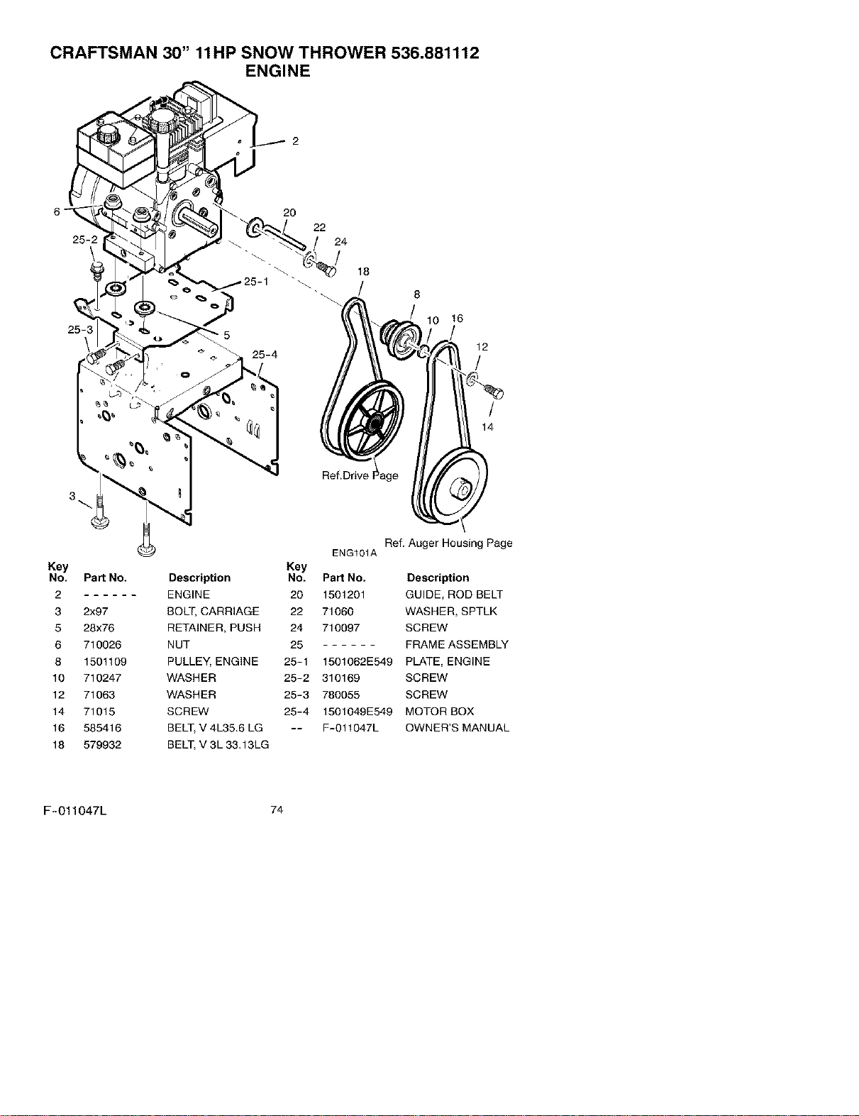
CRAFTSMAN 30" 11HP SNOW THROWER 536.881112
ENGINE
25-2
25-3 " 5
3
20
22
24
18
/
Ref.Drive
10 16
12
/
/
14
Ref. Auger Housing Page
ENG101A
Key Key
No. Part No. Description No. Part No. Description
2 ENGINE 20 1501201 GUIDE, ROD BELT
3 2x97 BOLT, CARRIAGE 22 71060 WASHER, SPTLK
5 28x76 RETAINER, PUSH 24 710097 SCREW
6 710026 NUT 25 FRAME ASSEMBLY
8 1501109 PULLEY, ENGINE 25-1 1501062E549 PLATE, ENGINE
10 710247 WASHER 25-2 310169 SCREW
12 71063 WASHER 25-3 780055 SCREW
14 71015 SCREW 25-4 1501049E549 MOTOR BOX
16 585416 BELT, V 4L35.6 LG -- F-011047L OWNER'S MANUAL
18 579932 BELT, V 3L 33.13LG
F-011047L 74
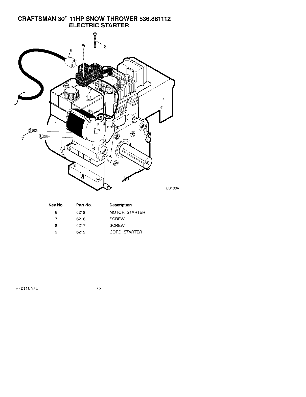
CRAFTSMAN 30" 11HP SNOW THROWER 536.881112
ELECTRIC STARTER
9
7
\
ES100A
Key No.
6
7
8
9
PaN No.
6218
6216
6217
6219
Description
MOTOR, STARTER
SCREW
SCREW
CORD, STARTER
F-011047L 75
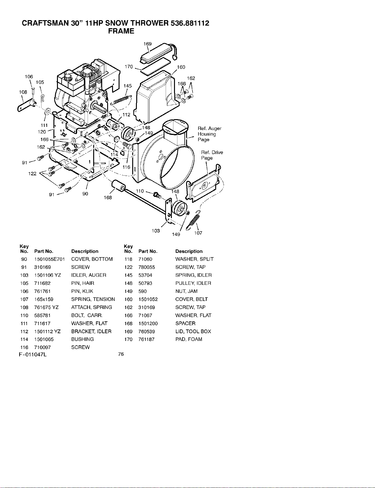
CRAFTSMAN 30" 11HP SNOW THROWER 536.881112
FRAME
169
106
\
108
160
162
91
168
Ref. Auger
Housing
Page
Ref. Drive
Page
Key
NO. Part NO.
90 1501055E701
91 310169
103 1501106YZ
105 711682
106 761761
107 165x159
108 761675YZ
110 585781
111 711617
112 1501112 YZ
114 1501065
116 710097
F-011047L
103
Key
Description No. Part No.
COVER, BOTTOM 118 71060
SCREW 122 780055
IDLER, AUGER 145 53704
PIN, HAIR 148 50793
PIN, KLIK 149 590
SPRING, TENSION 160 1501052
ATTACH, SPRING 162 310169
BOLT, CARR. 166 71067
WASHER, FLAT 168 1501200
BRACKET, IDLER 169 760539
BUSHING 170 761187
SCREW
76
149 107
Desori_ion
WASHER, SPLIT
SCREW, TAP
SPRING, IDLER
PULLE_IDLER
NU_ JAM
COVER, BELT
SCREW, TAP
WASHER, FLAT
SPACER
LID, TOOL BOX
PAD, FOAM
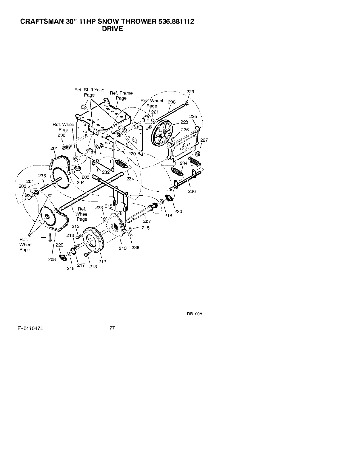
CRAFTSMAN 30" 11HP SNOW THROWER 536.881112
DRIVE
Ref. Shift Yoke
Ref. Frame _-_ 229
Page
Page -"
2OO
Ref. Whee
Page
206
\
201
\
225
\/
227
/
f
/
/ 204
203
\
\
Ref,
Wheel
Page
236
208
\
212
217 213
218
207
215
\
210 238
218
230
\
220
DR100A
F-O11047L 77
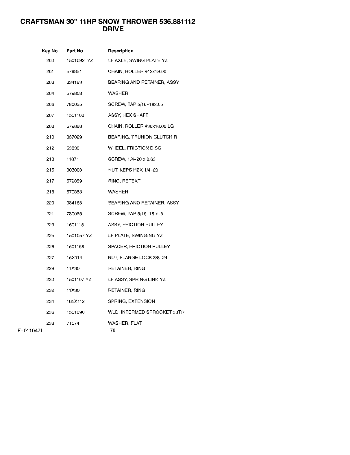
CRAFTSMAN 30" 11HP SNOW THROWER 536.881112
DRIVE
F-011047L
Key No. Part No. Description
200 1501092 YZ LF AXLE, SWING PLATE YZ
201 579851 CHAIN, ROLLER #42x19.00
203 334163 REARING AND RETAINER, ASSY
204 579858 WASHER
206 780055 SCREW, TAP 5/16-18x0.5
207 1501100 ASSY, HEX SHAFT
208 579868 CHAIN, ROLLER #36x18.00 LG
210 337029 BEARING, TRUNION CLUTCH R
212 53830 WHEEL, FR_CTION DISC
213 11871 SCREW, 1/4-20 x 0.63
215 303008 NUT, KEPS HEX 1/4-20
217 579859 RING, RETEXT
218 579858 WASHER
220 334163 REARING AND RETAINER, ASSY
221 780055 SCREW, TAP 5/16-18 x .5
223 1501115 ASSY, FRICTION PULLEY
225 1501057 YZ LF PLATE, SWINGING YZ
226 1501158 SPACER, FRICTION PULLEY
227 15Xl14 NUT, FLANGE LOCK 3/8-24
229 11X30 RETAINER, R_NG
230 1501107 YZ LF ASSY, SPRING LINK YZ
232 11X30 RETAINER, R_NG
234 165Xl12 SPRING, EXTENSION
236 1501090 WLD, INTERMED SPROCKET 33-1-/7
238 71074 WASHER, FLAT
78
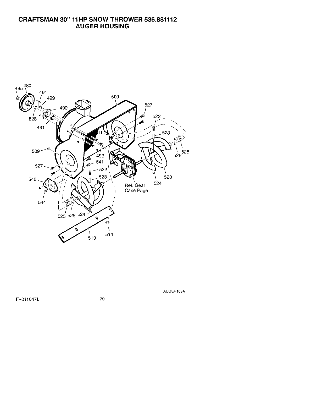
CRAFTSMAN 30" 11HP SNOW THROWER 536.881112
AUGER HOUSING
_85 480
481
499 500
528
491
527
522
523_ _
509
525
/
544
525 526 524
510
\
514
Ref. Gear
Case Page
\ 520
524
AUGER103A
F-011047L 79
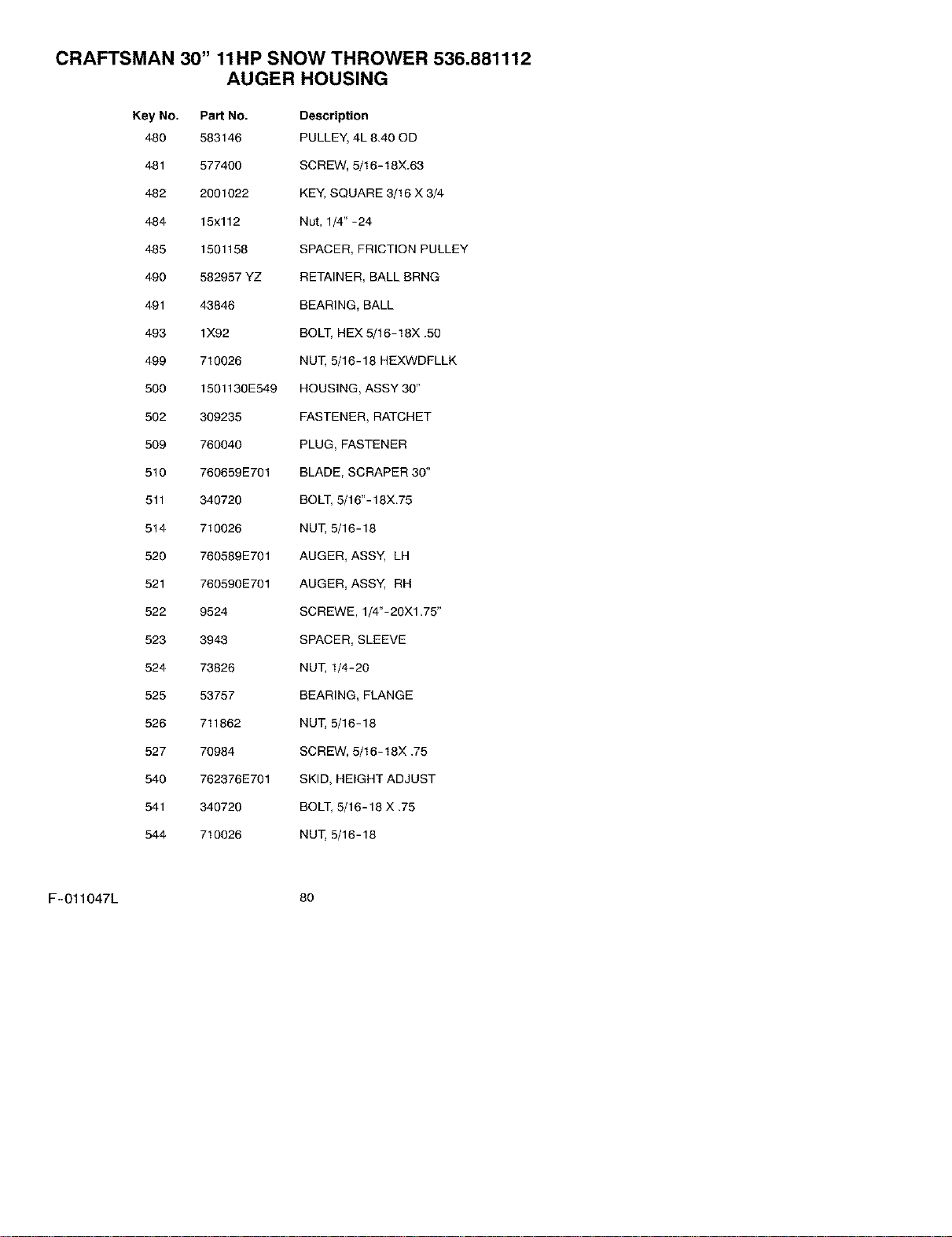
CRAFTSMAN 30" 11HP SNOW THROWER 536.881112
AUGER HOUSING
Key No. Part No. Description
480 583146 PULLEY, 4L 8.40 OD
481 577400 SCREW, 5/16-18X.63
482 2001022 KEY, SQUARE 3/16 X 3/4
484 15x112 Nut, 1/4" -24
485 1501158 SPACER, FRICTION PULLEY
490 582957 YZ RETAINER, BALL BRNG
491 43846 BEARING, BALL
493 lX92 BOLT, HEX 5/16-18X .50
499 710026 NUT, 5/16-18 HEXWDPLLK
500 1501130E549 HOUSING, ASSY 30"
502 309235 FASTENER, RATCHET
509 760040 PLUG, FASTENER
510 760659E701 BLADE, SCRAPER 30"
511 340720 BOLT, 5/16"- 18X.75
514 710026 NUT, 5/16-18
520 760589E701 AUGER, ASSY, LH
521 760590E701 AUGER, ASSY, RH
522 9524 SCREWE, 1/4"-20Xl .75"
523 3943 SPACER, SLEEVE
524 73826 NUT, 1/4-20
525 53757 BEARING, FLANGE
526 711862 NUT, 5/16-18
527 70984 SCREW, 5/16-18X .75
540 762376E701 SKID, HEIGHT ADJUST
541 340720 BOLT, 5/16-18 X .75
544 710026 NUT, 5/16-18
F-011047L 8o
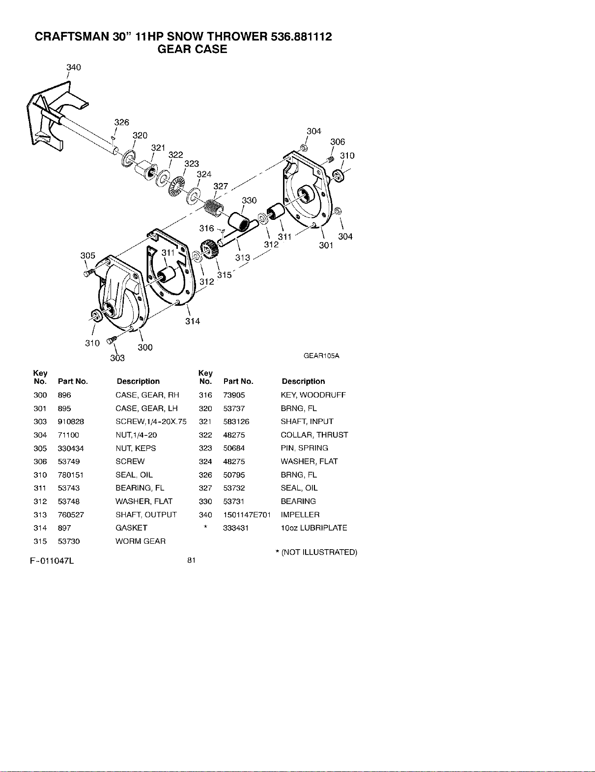
CRAFTSMAN 30" 11HP SNOW THROWER 536.881112
GEAR CASE
340
/
305
\
326
304
320 /
321
322
323
324
f
327 _
330
316
312
313_
315_
12
306
310
\
304
301
314
/
310 \ 300
303
Key Key
No. Part No. Description No. Part No.
300 896 CASE, GEAR, RH 316 73905
301 895 CASE, GEAR, LH 320 53737
303 910828 SCREW,1/4-2OX.75 321 583126
304 71100 NUT,1/4-2O 322 48275
305 330434 NUT, KEPS 323 50684
306 53749 SCREW 324 48275
310 780151 SEAL, O_L 326 50795
311 53743 BEARING, FL 327 53732
312 53748 WASHER_ FLAT 330 53731
313 760527 SHAFT, OUTPUT 340 15011471=701
314 897 GASKET 333431
315 53730 WORM GEAR
F-011047L
81
GEARt05A
Description
KEY, WOODRUFF
BRNG, FL
SHAFT, INPUT
COLLAR, THRUST
PiN, SPRING
WASHER, FLAT
BRNG, FL
SEAL, OIL
BEARING
IMPELLER
1Ooz LUBRIPLATE
* (NOT ILLUSTRATED)
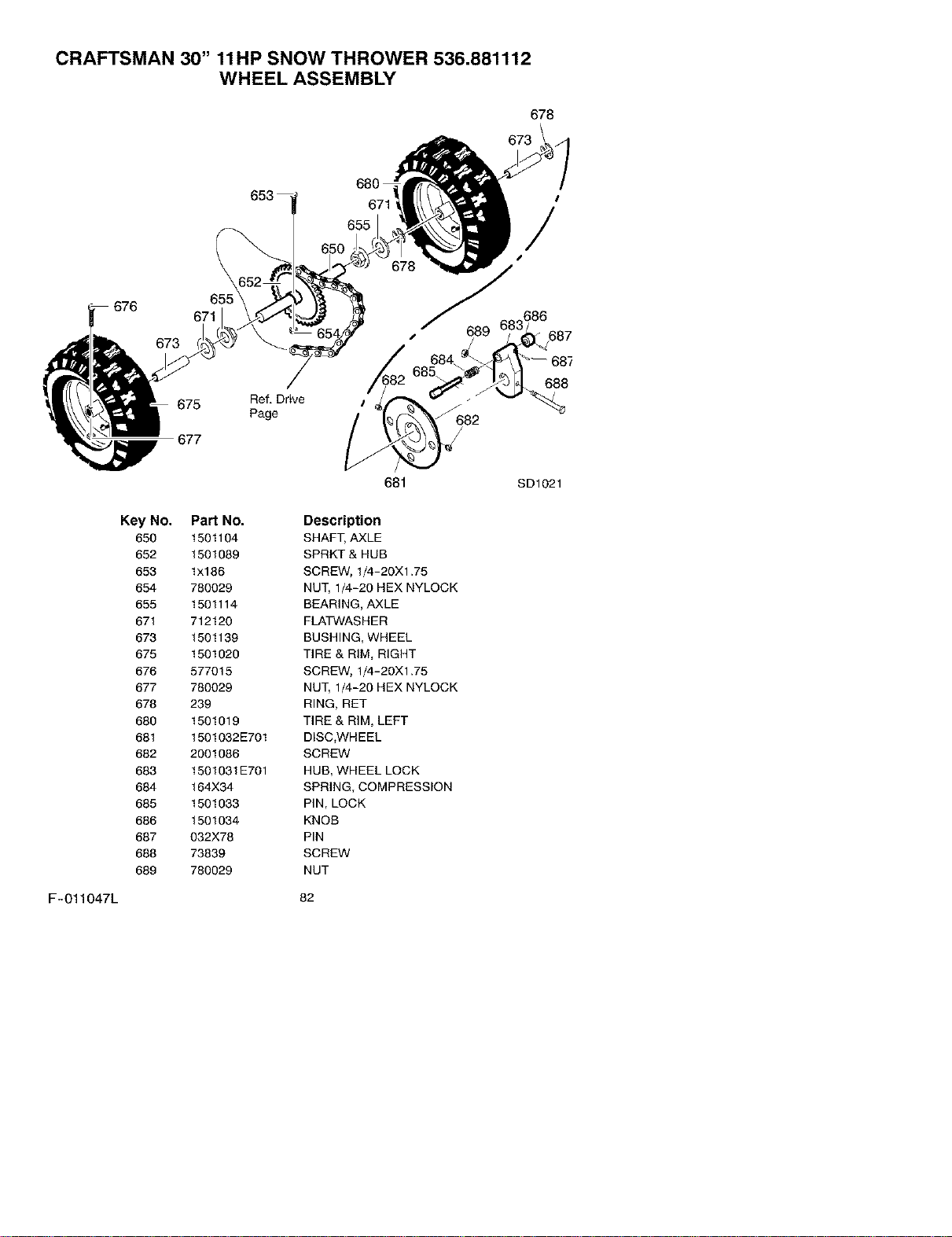
CRAFTSMAN 30" 11HP SNOW THROWER 536.881112
WHEEL ASSEMBLY
678
673
676
671
673
675
677
Ref, Drive
Page
680
655
687
688
Key No.
650
652
653
654
655
671
673
675
676
677
678
680
681
682
683
684
685
689
687
688
689
PaN No.
1501104
1501089
lx186
780029
1501114
712120
1501139
1501020
577015
780029
239
1501019
1501032E701
2001086
1501031E701
164X34
1501033
1501034
032X78
73839
780029
681
Description
SHAFT, AXLE
SPRKT & HUB
SCREW, 1/4-20X1.75
NUT, 1/4-20 HEX NYLOCK
BEARING, AXLE
FLATWASHER
BUSHING, WHEEL
TIRE & RIM, RIGHT
SCREW, 1/4-20X1.75
NUT, 1/4-20 HEX NYLOCK
RING, RET
TIRE & RIM, LEFT
DISC,WHEEL
SCREW
HUB, WHEEL LOCK
SPRING, COMPRESSION
PIN, LOCK
KNOB
PIN
SCREW
NUT
SD1021
F-011047L 82
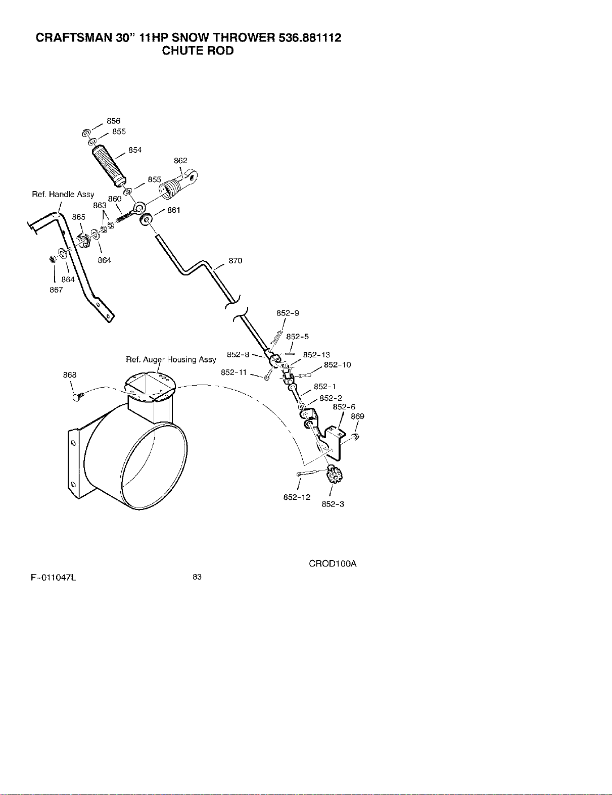
CRAFTSMAN 30" 11HP SNOW THROWER 536.881112
CHUTE ROD
856
854
862
Ref. Handle Assy
863
/ 861
864 870
L
867
_rHousing Assy
868
852-9
/
\
852-1
852-6
869
/
/ /
852-12
852-3
CROD100A
F-011047L 83

CRAFTSMAN 30" 11HP SNOW THROWER 536.881112
CHUTE ROD
Key No. Part No. Description
852-1 1501076 YZ ASSEMBLY, YOKE & ROD
852-2 313431 WASHER, CURVED SPRING
852-3 1501067 GEAR, CHUTE ROTATION 9T
852-5 71082 PIN, COTTER
852-6 1501051V701 BRACKET, GEAR MOUNT
852-7 579493 PIN, COTTER
852-8 1501075 YZ ASSEMBLY, YOKE ADAPTER YZ
852-9 711682 PIN, HAIR
852-10 578060 PIN, UNIVERSAL JOINT
852-11 578309 PIN, CLEVIS
852-12 579493 PIN, COTTER
852-13 578063 HOUSING, UNIVERSAL
854 307399 HANDLE, CRANK
855 309312 FLATWASHER
856 73664 NUT, PUSH
860 581618 EYE BOLT 3/8-16X6.00
861 148 GROMMET, EYE BOLT
862 308145 BOOT, EYE BOLT
863 71045 NUT, 3/8-16 HEXJAM
864 71072 FLATWASHER .406X.81X.066
865 309344 ADAPTER, BOOT
866 71072 WASHER
867 71046 NUT, 3/8-16 HEXNYL
868 2X98 BOLT, CARRIAGE 1/4-20 X 1.00
869 780029 NUT, 1/4-20
870 1501074 CRANK, ASSY CHUTE
F-011047L 84
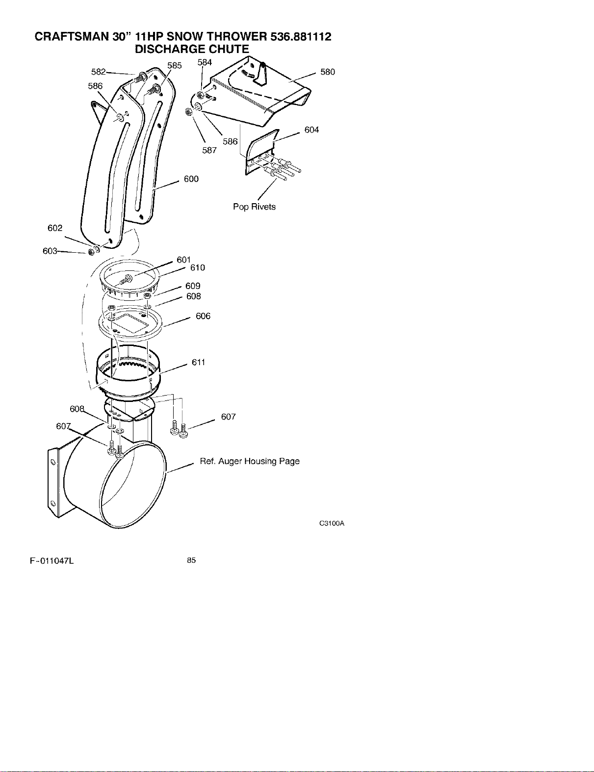
CRAFTSMAN 30" 11HP SNOW THROWER 536.881112
DISCHARGE CHUTE
582_
586
601
610
608
606
611
607
Ref. Auger Housing Page
C3100A
F-011047L 85

CRAFTSMAN 30" 11HP SNOW THROWER 536.881112
DISCHARGE CHUTE
Key No. Part No. Description
580 761168E701 CHUTE, UPPER W/REMOTE
582 578088 SCREW, 5/16-18 X.75
584 71038 NUT
585 578088 SCREW, 5/16-18 X.75
586 6711 PLASTIC WASHER
587 71038 NUT
600 761169E701 CHUTE, LOWER W/REMOTE
601 586280 BOLT
602 71071 WASHER_ FLAT
603 71038 NUT
604 762322 FLAP
606 585214 YZ CHUTE COLLAR
607 002X98 BOLT
608 71067 WASHER, FLAT
609 780029 NUT
610 337227 RETAINER, RING INNER
611 1501054 RETAINER, RING OUTER
F-011047L 86
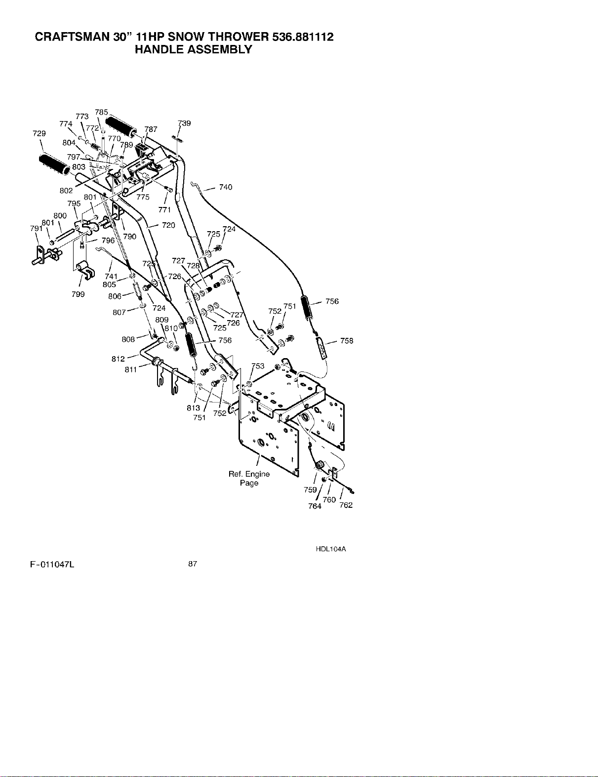
CRAFTSMAN 30" 11HP SNOW THROWER 536.881112
HANDLE ASSEMBLY
773
774
729 _,
\
802
801
795
80O
740
799
756
813
751
Ref, Engine
Page
764
HDL104A
F-011047L 87
CRAFTSMAN 30" 11HP SNOW THROWER 536.881112
HANDLE ASSEMBLY
Key Key
No. Part No. Description No. Part No. Description
720 760192E701 ASSY, HANDLE 773 71072 WASHER, FLAT
723 71007 SCREW 774 71046 NUT, HEX
724 7288 SCREW 775 579183 SPACER, SHIFT
725 71072 WASHER, FLAT 785 71034 NUT, HEX
726 71062 WASHER 787 585522 KNOB, SHIFT
727 71044 NUT 790 578926 ROD, ASSY LH
728 7289 STOP, PLASTIC 791 578924 ROD, ASSY RH
729 50792 GRIP, HANDLE 795 579002 BRACKET, CAM
739 4049 BUMPER 796 313676 SCREW
740 1501124 CABLE, CLUTCH 797 71060 WASHER, SPTLK
741 761591 CABLE, CLUTCH 798 71037 NUT, HEX
743 579869 TENSION SPRING 799 8417 CAM LOCK
744 1673 SPRING, CLUTCH 800 584673 PIN, SPRING PIVOT
745 780029 NUT, HEX 801 73664 NUT, PUSH ON
750 5543EE701 HANDLE, LOWER 802 71081 PIN, COTTER
751 70984 SCREW 803 71071 FLATWASHER
752 71060 WASHER, SPTLK 804 581079 ROD, CONTROL
753 71391 NUT 805 71042 NUT, HEX
754 70984 SCREW 806 6352 ADAPTOR, SPEED
756 308146 BOOT, CABLE 807 71060 WASHER
758 lX186 BOLT, HEX 808 50782 JOINT, STEEL BALL
759 1501122 SPOOL, CABLE 809 71060 WASHER
760 1501059 YZ BRKT, SPOOL 810 71042 NUT, HEX
762 1501122 CABLE, DRIVE 811 579944 BEARING, FL
770 581964 BRACKET, SHIFT 812 1501110 TZ ROD, YOKE
771 7288 SCREW 813 11X30 RETAINER, RING
772 50786 SPRING
F-011047L 88
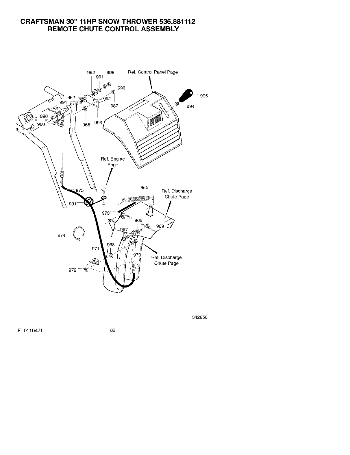
CRAFTSMAN 30" 11HP SNOW THROWER 536.881112
REMOTE CHUTE CONTROL ASSEMBLY
992 996 Ref. Control Panel Page
996
#92
991
982
i
966 993
/_994 995
Ref. Engine
Page
/
965
Ref. Discharge
Chute Page
971
966
969
h,,,
970 Ref. Discharge
Chute Page
342858
F-011047L 89
CRAFTSMAN 30" 11HP SNOW THROWER 536.881112
REMOTE CHUTE CONTROL ASSEMBLY
Key No. Part No. Description
965 318468 SPRING_ TENSION RETURN
966 711666 WASHER, FLAT
967 310088 BOLT, 5/16-18
968 73787 WASHER, FLAT
969 302635 NUT, 1/4-20
970 313676 SCREW, 5/16-18 X .75
971 780066 BRACKET, CABLE CHUTE
972 71391 NUT, 5/16-18
973 55021 TRIM
974 760113 T_E, CABLE
975 761131 CABLE, CHUTE CONTROL
980 310088 BOLT, 5/16-18
981 780220 WIRE FORM
982 302635 NUT, 1/4-10
990 4058 SCREW, 3/8-16Xl .75
991 71072 WASHER, FLAT
992 4051 WASHER, SPR_NG
993 579040 HANDLE ASSY, SPEED CONTROL
994 71044 NUT, 3/8-16 REGHEX
995 306689 HANDLE, 3/8-16 MOLDED
996 71046 NUT, 3/8-16 HEX
F-011047L 9o
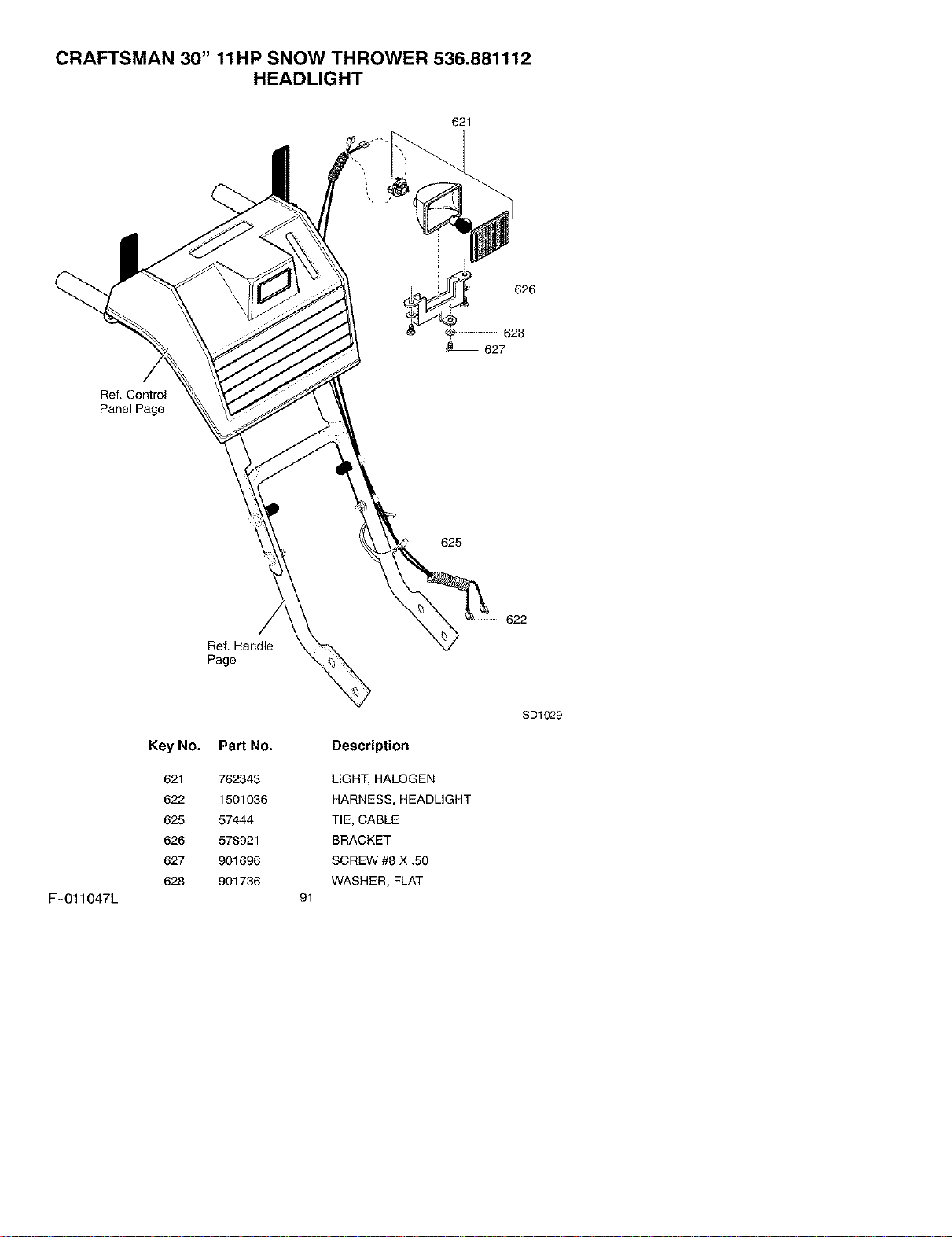
CRAFTSMAN 30" 11HP SNOW THROWER 536.881112
HEADLIGHT
621
-- 628
627
Ref. Control
Panel Page
625
Ref. Handle
Page
F-011047L
Key No,
621
622
625
626
627
628
Part No.
762343
1501036
57444
578921
901696
901736
Description
LIGHT, HALOGEN
HARNESS, HEADLIGHT
TIE, CABLE
BRACKET
SCREW #8 X .50
WASHER, FLAT
91
SD1029
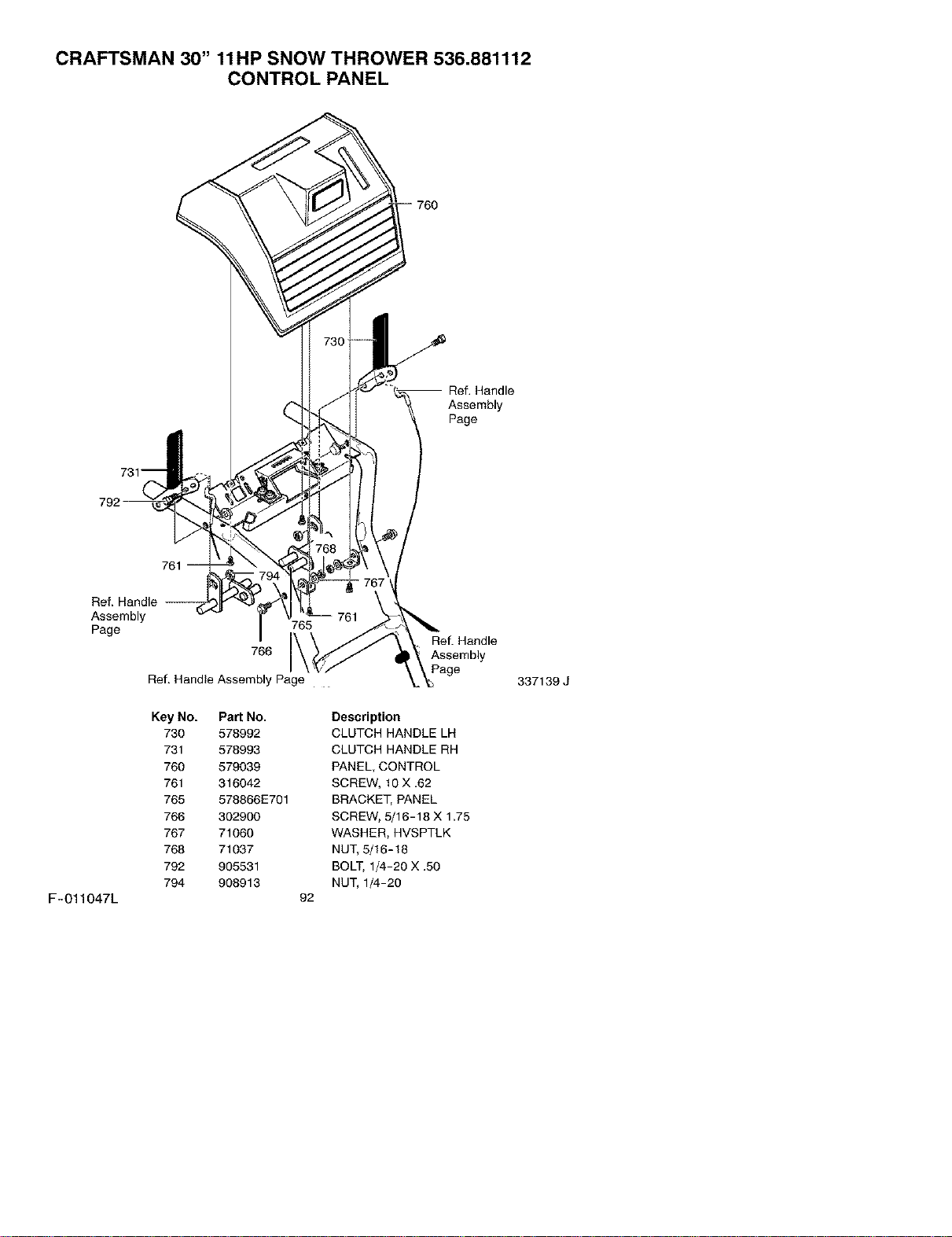
CRAFTSMAN 30" 11HP SNOW THROWER 536.881112
CONTROL PANEL
760
-- Ref. Handle
Assembly
Page
F-011047L
761
Ref. Handle
Assembly
Page
Ref. Handle
Key No.
730
731
760
761
765
766
767
768
792
794
766
Assembly Page .
Pad No.
578992
578993
579039
316042
578866E701
302900
71060
71037
905531
908913
Ref. Handle
Assembly
Page
Description
CLUTCH HANDLE LH
CLUTCH HANDLE RH
PANEL, CONTROL
SCREW, 10 X.62
BRACKE_ PANEL
SCREW, 5/16-18 X 1.75
WASHER, HVSPTLK
NU_ _16-18
BOLT, I_-2O X.5O
NU_ 1_-20
92
337139 J
CRAFTSMAN 30" 11HP SNOW THROWER 536.881112
NOTILLUSTRATED
DECALS
Part No.
761776
761916
48x399
761078
48x2003
48x2001
48x2002
48x358
760983
48x2000
Description
DECAL DANGER & FOOT
DECAL DANGER CHUTE -HAND
DECAL 11_0 CRAFTSMAN
DECAL DANGER STRIPE
DECAL REMOTECHUTETRACTENGAGE
DECAL SPEED SELECT
DECAL AUGER ENGAGE
NAMEPLATE, CRAFTSMAN
DECAL, TOOLBOX-BELTCOVER
DECAL, SCH.
F-011047L 93
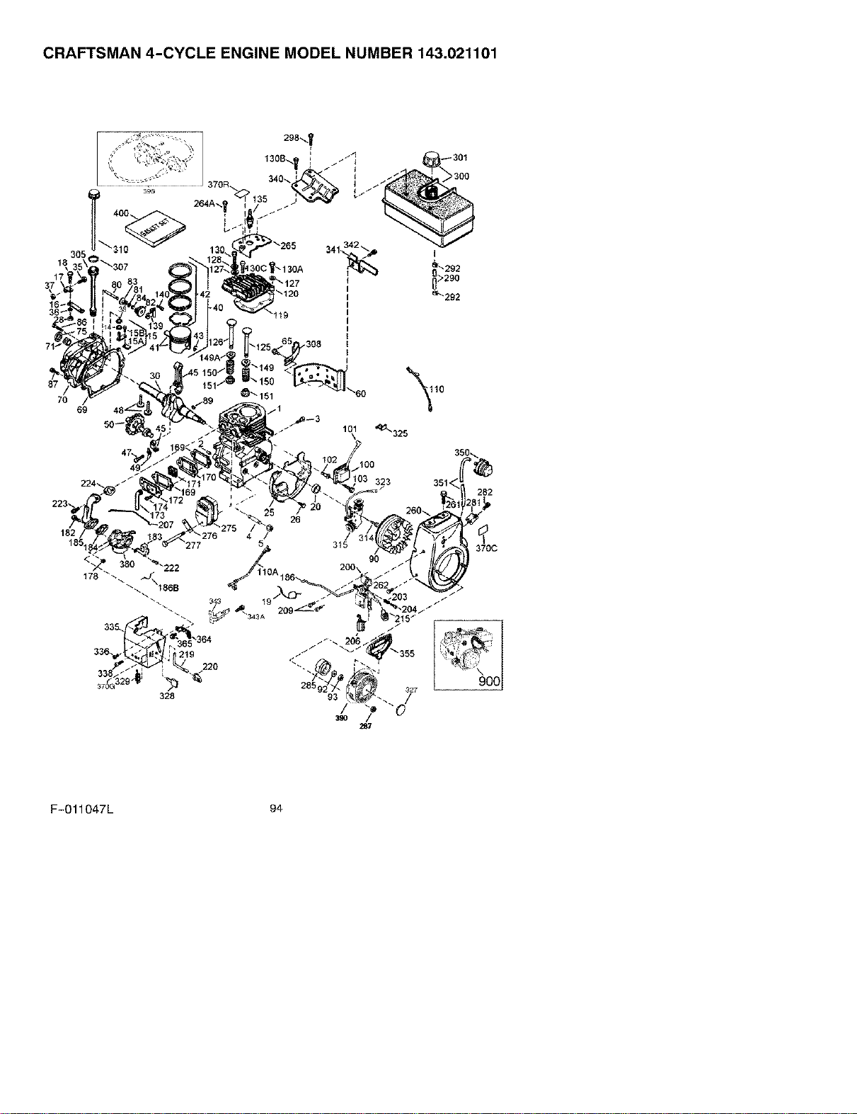
CRAFTSMAN 4-CYCLE ENGINE MODEL NUMBER 143.021101
87 %_1070
69 48_
292
290
e_292
370C
F-O11047L 94
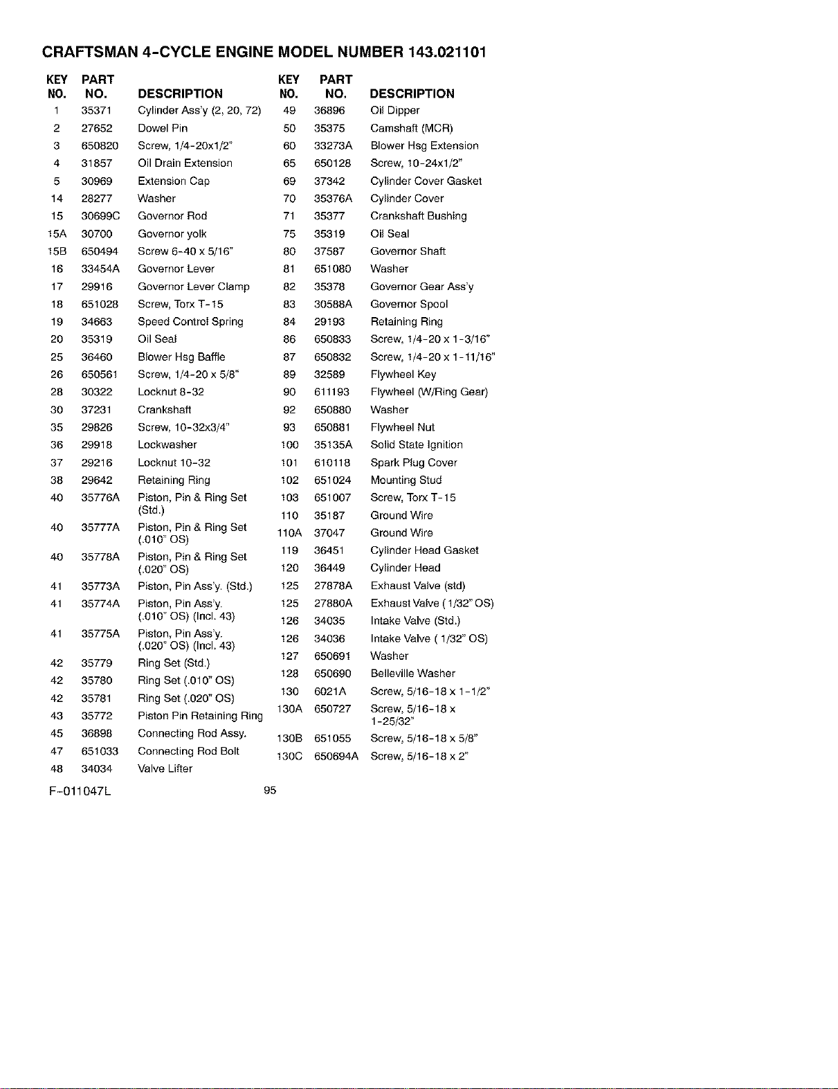
CRAFTSMAN 4-CYCLE ENGINE MODEL NUMBER 143.021101
KEY PART KEY PART
NO. NO. DESCRIPTION NO. NO. DESCRIPTION
1 35371 Cylinder Ass'y (2, 20, 72) 49 36896 Oil Dipper
2 27652 Dowel Pin 50 35375 Camshaft (MCR)
3 650820 Screw, 1/4-20xl/2" 60 33273A Blower Hsg Extension
4 31857 Oil Drain Extension 65 650128 Screw, 10-24xl/2"
5 30969 Extension Cap 69 37342 Cylinder Cover Gasket
14 28277 Washer 70 35376A Cylinder Cover
15 30699C Governor Rod 71 35377 Crankshaft Bushing
15A 30700 Governor yolk 75 35319 Oil Seal
15B 650494 Screw 6-40 x 5/16" 80 37587 Governor Shaft
16 33454A Governor Lever 81 651080 Washer
17 29916 Governor Lever Clamp 82 35378 Governor Gear Ass'y
18 651028 Screw, Torx T- 15 83 30588A Governor Spool
19 34663 Speed Control Spring 84 29193 Retaining Ring
20 35319 Oil Seal 86 650833 Screw, 1/4-20 x 1-3/16"
25 36460 Blower Hsg Baffle 87 650832 Screw, 1/4-20 x 1-11/16"
26 650561 Screw, 1/4-20 x 5/8" 89 32589 Flywheel Key
28 30322 Locknut 8-32 90 611193 Flywheel (W/Ring Gear)
30 37231 Crankshaft 92 650880 Washer
35 29826 Screw, 10-32x3/4" 93 650881 Flywheel Nut
36 29918 Lockwasher 100 35135A Solid State Ignition
37 29216 Locknut 10-32 101 610118 Spark Plug Cover
38 29642 Retaining Ring 102 651024 Mounting Stud
40 35776A Piston, Pin & Ring Set 103 651007 Screw, Torx T- 15
(Std.) 110 35187 Ground Wire
40 35777A Piston, Pin & Ring Set 110A 37047 Ground Wire
(.OtO"OS)
119 36451 Cylinder Head Gasket
40 35778A Piston, Pin & Ring Set
(.620" OS) 120 36449 Cylinder Head
41 35773A Piston, Pin Ass'y. (Std.) 125 27676A Exhaust Valve (std)
41 35774A Piston, Pin Ass'y. 125 27680A Exhaust Valve (1/32"OS)
(.610" OS) (Incl. 43) 126 34035 Intake Valve (Std.)
41 35775A Piston, Pin Ass'y. 126 34036 Intake Valve ( 1/32" OS)
(.020" OS) (Incl. 43)
127 650691 Washer
42 35779 Ring Set (Std.)
126 656696 Belleville Washer
42 35780 Ring Set (.010" OS)
130 6021A Screw, 5/16-18 x 1-1/2"
42 35781 Ring Set (.020" OS)
130A 650727 Screw, 5/16-18 x
43 35772 Piston Pin Retaining Ring 1-25/32"
45 36696 Connecting Rod Assy. 130B 651055 Screw, 5/16-18 x 5/8"
47 651033 Connecting Rod Bolt 130C 650694A Screw, 5/16-18 x 2"
48 34034 Valve Lifter
F-011047L 95

CRAFTSMAN 4-CYCLE ENGINE MODEL NUMBER 143.021101
135 35395 Spark Plug (RJ1 9LM) 281 33013 Starter Bubble Cover
139 33369 Governor Gear Bracket 282 650760 Screw, 8-32 x 3/8"
140 659836 Screw, 10-24 x 1/2" 285 35985B Starter Cup
149 27882 Valve Spring Cap 287 29752 Nut & Lockwasher
149A 35862 Valve Spring Cap 290 30962 Fuel Line
150 27881 Valve Spring 292 26460 Fuel Line Clamp
151 32581 Valve Spring Keeper 298 650665 Screw, 1/4-15 x 3/4"
169 27896A Valve Cover Gasket 300 34186A Fuel Tank
170 28423 Breather Body 301 35355 Fuel Cap
171 28424 Breather Element 305 35554 Oil Fill Tube
172 28425 Valve Cover 307 35499 "O" Ring
173 35350 Breather Tube 308 35540 Fill Tube Clip
174 650128 Screw, 10-24 x 1/2" 310 36205 Dipstick
178 29752 Nut & Lock Washer 314 650873 Screw, 1/4-20 x 3/4"
182 30088A Screw, 1/4-28 x 1" 315 611111 Alternator Coil
183 34587A Choke Bracket 323 611118 Carburetor Terminal
184 33263 Carb. To Intk Pipe Gasket 325 29443 Wire Clip
185 33877 Intake Pipe 327 35392 Starter Plug
186 34667 Governor Link 328 35593 Ignition Key
186B 36652 Choke Spring 329 610973 Terminal
200 34677 Control Bracket 335 36547 Carburetor Cover
203 31342 Compression Spring 336 650765 Screw, 10-32 x 1/2"
204 651029 Screw, Torx T- 10 338 28942 Screw, 10-32 x 3/8"
206 610973 Terminal 340 34154 Fuel Tank Bracket
207 33878 Throttle Link 341 34155 Fuel Tank Bracket
209 650821 Screw, 10-32 x 1/2" 342 650561 Screw, 1/4-20 x 5/8"
215 35440 Control Knob 343 35079A Key Switch Bracket
219 34586 Choke Rod 343A 651060 Screw, 10-32 x 23/64"
220 35438 Choke Knob 350 570682A Primer Ass'y
222 651081 Screw, 10-32 x 15/32" 351 32180C Primer Line
223 650378 Screw, Torx T-4O 355 590574 Starter Handle
224 27915A Intake Pipe Gasket 364 33337 Carburetor Cover Bracket
260 35447A Blower Housing 365 650767 Screw, 8-32 x 27/64"
261 650788 Screw, 5/16-18 x 3/4" 370C 36501 Primer Decal
262 29747B Screw, 5/16-24 x 21/32" 370G 35077 Control Decal
264A 650802 Screw, 1/4-20 x 5/8" 370R 37580 Warning Decal
265 33272D Cyclinder Head Cover 380 640054 Carburetor (Incl. 184)
275 35056 Muffler 390 590749 Rewind Starter
276 31588 Locking Plate 396 33329E Electric Start Motor (Opt)
277 651002 Screw, 5/16-18x4-3/16" 400 36452B Gasket Set
F-O11047L 96

CRAFTSMAN 4-CYCLE ENGINE MODEL NUMBER 143.021101
12 13
KEY
NO.
O
1
2
3
4
6
7
6
11
12
13
F-011047L
PART
NO,
590749
590599A
590600
590679
590601
590680
590412
590682
590750
590535
590574
DESCRIPTION
Rewind Starter
Spring Pin
Washer
Retainer
Washer
Starter Dog
Dog Spring
Pulley & Rewind Spring Assy.
Starter Housing Ass'y.
Starter Rope (Length 98" x 9/64" dia.)
Mitten Grip Handle (Not included with starter)
97
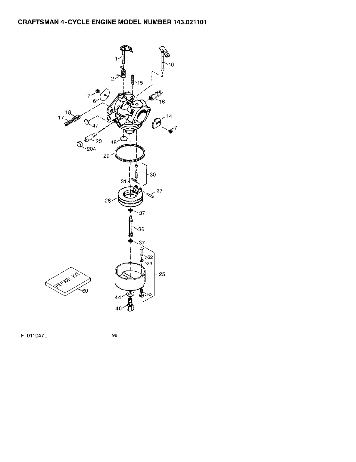
CRAFTSMAN 4-CYCLE ENGINE MODEL NUMBER 143.021101
60
- 25
F-O11047L 98
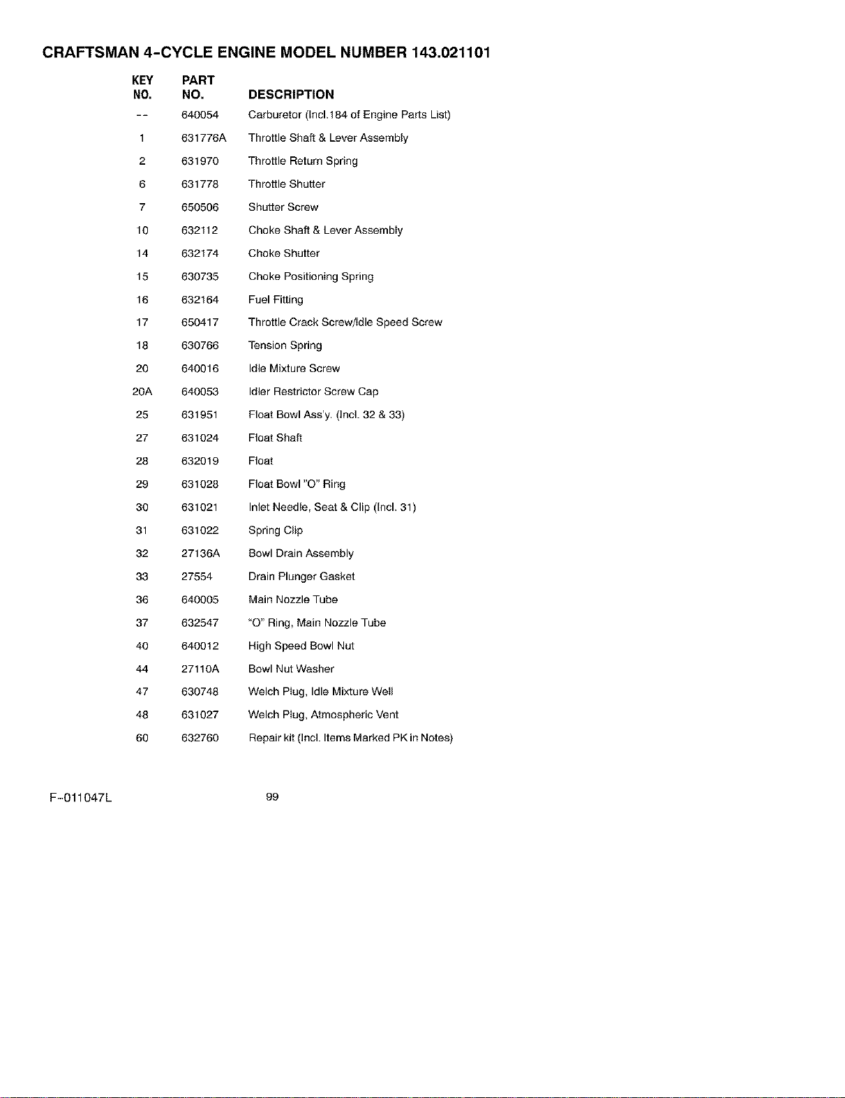
CRAFTSMAN 4-CYCLE ENGINE MODEL NUMBER 143.021101
KEY PART
NO. NO. DESCRIPTION
-- 640054 Carburetor (Inc1,184 of Engine Parts List)
1 631776A Throttle Shaft & Lever Assembly
2 631970 Throttle Return Spring
6 631778 Throttle Shutter
7 650506 Shutter Screw
10 632112 Choke Shaft & Lever Assembly
14 632174 Choke Shutter
15 630735 Choke Positioning Spring
16 632164 Fuel Fitting
17 650417 Throttle Crack Screw/Idle Speed Screw
18 630766 Tension Spring
20 640016 Idle Mixture Screw
20A 640053 Idler Restrictor Screw Cap
25 631951 Float Bowl Ass'y. (Incl. 32 & 33)
27 631024 Float Shaft
28 632019 Float
29 631028 Float Bowl "O" Ring
30 631021 Inlet Needle, Seat & Clip (Incl. 31)
31 631022 Spring Clip
32 27136A Bowl Drain Assembly
33 27554 Drain Plunger Gasket
36 640005 Main Nozzle Tube
37 632547 "O" Ring, Main Nozzle Tube
40 640012 High Speed Bowl Nut
44 27110A Bowl Nut Washer
47 630748 Welch Plug, Idle Mixture Well
48 631027 Welch Plug, Atmospheric Vent
60 632760 Repair kit (Incl. Items Marked PK in Notes)
F-011047L 99
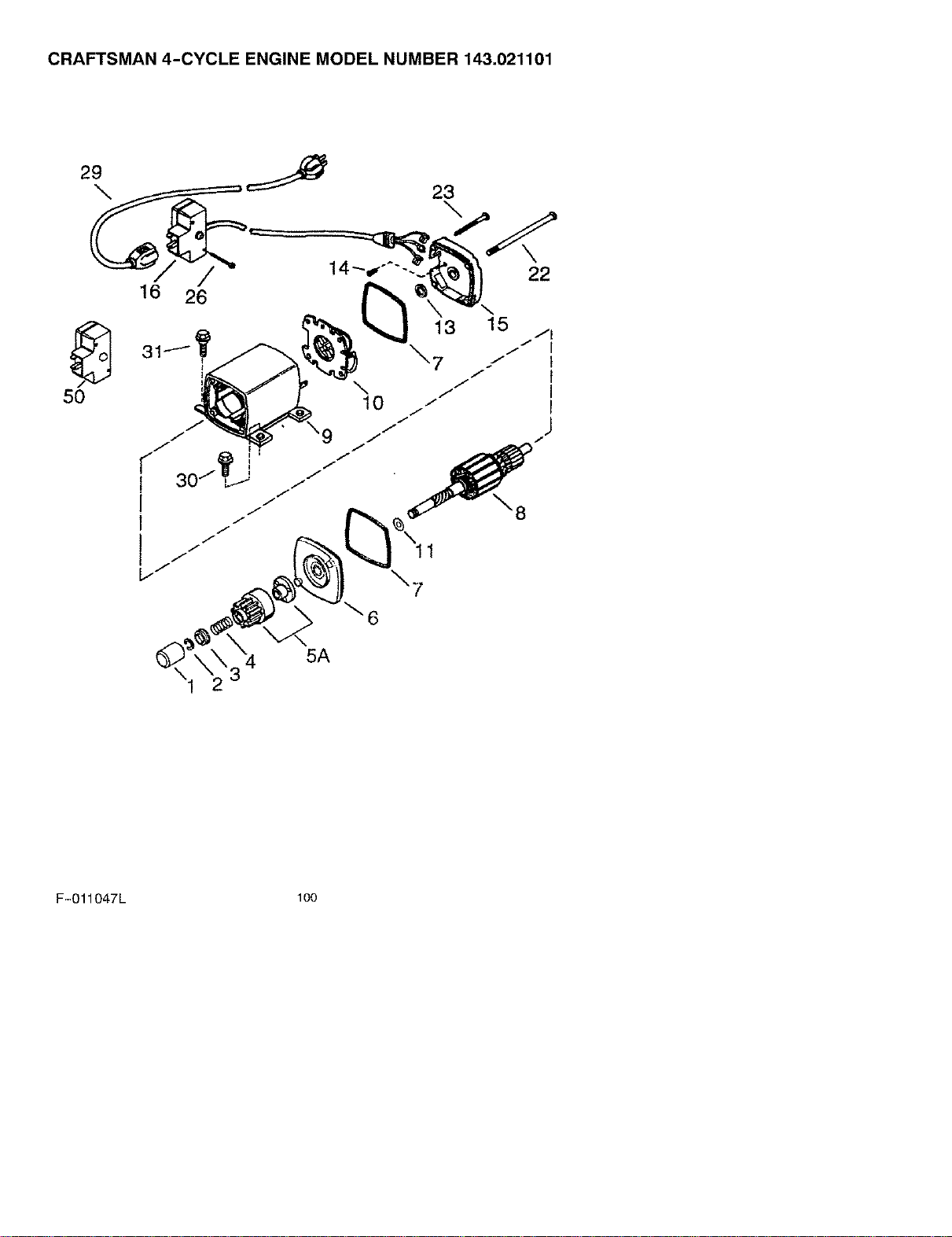
CRAFTSMAN 4-CYCLE ENGINE MODEL NUMBER 143.021101
29
16 26
50
\
22
1
\7
\6
5A
F-O11047L lOO
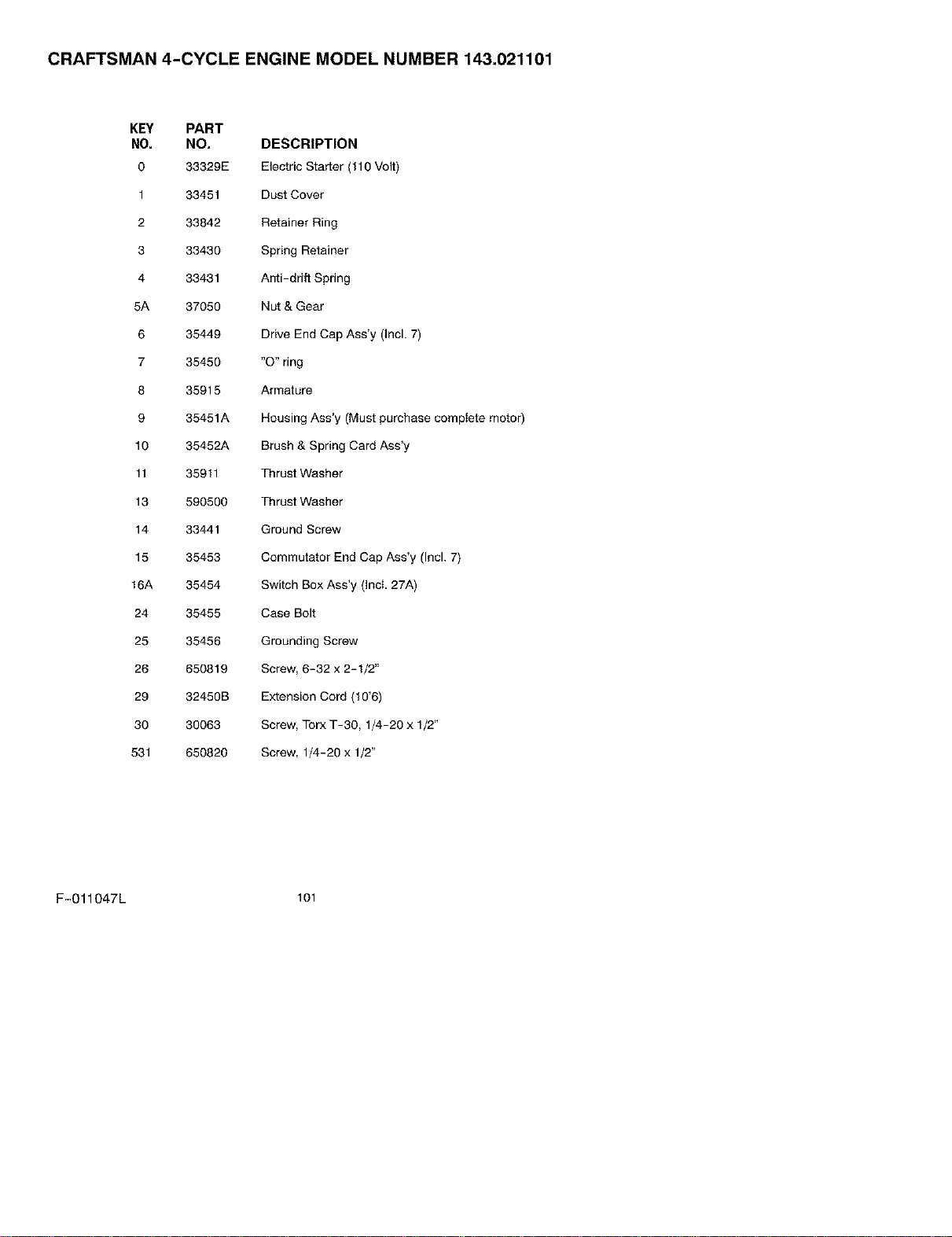
CRAFTSMAN 4-CYCLE ENGINE MODEL NUMBER 143.021101
KEY PART
NO. NO, DESCRIPTION
0 33329E Electric Starter (110 Volt)
1 33451 Dust Cover
2 33842 Retainer Ring
3 33430 Spring Retainer
4 33431 Anti-drift Spring
5A 37050 Nut & Gear
6 35449 Drive End Cap Ass'y (Incl. 7)
7 35450 "O" ring
8 35915 Armature
9 35451A Housing Ass'y (Must purchase complete motor)
10 35452A Brush & Spring Card Ass'y
11 35911 Thrust Washer
13 590500 Thrust Washer
14 33441 Ground Screw
15 35453 Commutator End Cap Ass'y (Incl. 7)
16A 35454 Switch Box Ass'y (Incl. 27A)
24 35455 Case Bolt
25 35456 Grounding Screw
26 650819 Screw, 6-32 x 2-1/2"
29 32450B Extension Cord (10'6)
30 30063 Screw, Torx T-30, 1/4-20 x 1/2"
531 650820 Screw, 1/4-20 x 1/2"
F-011047L lOl


