MODEL NUMBER 917.376960
OWNER'S MANUAL
®
®Assembny
° Operation
° Customer
Responsibilities
• Service
- Adjustments
• Repair Parts
Caution:
Read and Follow
all Safety Rules
and Instructions
Before Operating
This Equipment
153596 Rev., 1 4.17,96 ksFFR Printed in U,.S.A
r t .....................I"'1
SAFETY RULES
Safe Operation Practices for Walk-Behind Mowers
IMPORTANT: THIS CUTTING MACHINE IS CAPABLE OF AMPUTATING HANDS AND FEE'[" AND THROWING OBJECTS
FAILURE TO OBSERVE THE FOLLOWING SAFETY iNSTRUCTiONS COULD RESULT IN SERIOUS iNJURY OR DEATH,
SAFETY STANDARDS REQUIRE OPERATOR PRESENCE CONTROLS TO MiNiMiZE THE RISK OF iNJURY, YOUR UNIT tS
EQUIPPED WITH SUCH CONTROLS, DO NOT ATTEMPT TO DEFEAT THE FUNCTION OF THE OPERATOR PRESENCE
CONTROLS UNDER ANY CIRCUMSTANCESo
TRAINING:
- Read thisoperator's manual carefully. Become familiar with
the controls and know how to operate your mower propedy,.
Leam how to quickly stop mower..
• Do not allow children to use your mower_ Never allow adults
to use mower without proper instructions.
° Keep the area of operation clear of all persons, especially
small children and pets.
= Use mower only as the manufacturer intended and as de-
scribed in this manual..
° Do not operate mower if it has been dropped or damaged in
any manner Always have damage repaired before using
your mower_
• Do notuse accessory attachments that are notrecommended
by the manufacturer, Use of such attachments may be
hazardous_
• The blade turns when the engine is running
PREPARATION:
• Always thoroughlycheck the area to be mowed and clear it of
al! stones, sticks, wires, bones, and other foreign objects_
These objects will be thrown by the blade and can cause
severe injury.,
* Always wear safety glasses or eye shields when starting and
while using your mower.
. Dress properly. Do not operate mower when barefoot or
wearing open sandals. Wear only solid shoes with good
traction when mowing.
° Check fuel tank before starting engine. Do not fill gas tank
indoors, when the engine is running or when the engine is hot.
Allow the engine to cool for several minutes before fillingthe
gas tank° Clean off any spilled gasoline before stading the
engine.
- Always make wheel height adjustments before starting your
mower.. Never attempt to do this while the engine is running.
= Mow only in daylight or good artificial light_
OPERATION:
- Keep your eyes and mind on your mower and the area being
cuL Do not let other interests distract you_
• Do not mow wet or slippery grass° Never run while operating
your mower. Aiways besure of your footing - keep a firm hold
on the handles and walk.
. Do not put hands or feet near or under rotating parts, Keep
clear of the discharge opening at afl times.,
° Always stop the engine whenever you leave or are not using
your mower, or before crossing driveways, walks, roads, and
any gravel-covered areas..
• Never direct discharge of mateda[ toward bystanders nor
allow anyone near the mower while you are operating it.
° Before cleaning, inspecting,or repairing your mower, stop the
engine and make absolutely sure the blade and all moving.
parts have stopped Then disconnect the spark plug wire and
keep it away from the spark plug to prevent accidental
starting_
° Do not continue to run your mower' if you hit a foreign object.
Follow the procedure outlined above, then repair any dam-
age before restarting and operating you mower.
• Do not change the governor settings or overspeed the
engine. Engine damage or personal injury may result.
• Do not operate your mower if it vibrates abnormally.. Exces-
sive vibration is an indication of damage; stop the engine,
safely check for the cause of vibration and repair as required.
Do not run the engine indoors° Exhaust fumes are danger-
OUS_
Never cut grass by pulling the mower towards you. Mow
across the face of slopes, never up and down or you might
lose your footing. Do not mow excessively steep slopes., Use
caution when operating the mower on uneven terrain or when
changing directions - maintain good footing.
• Never operate your mower without proper guards,_lates,
grass catcher or other safety devices in pJace_ '_
t
Check the blade and the engine mounting bolts ofte_ to be
sure they are tightened properly
,, Check all bolts, nuts and screws at frequent intervals for
proper tightness to be sure mower is in safe working condi-
tion.
• Keep all safety devices in place and working
= To reduce fire hazard, keep the engine free of grass, leaves
or excessive grease and oil.,
• Check grass catcher often for deterioration and wear and
replace worn bags, Use only repEacement bags that are
recommended by and comply with specifications of the
manufacturer' of your mower.
° Always keep a sharp blade on your mower,,
• Allow engine to cool before storing in any enclosure.
• Never store mower with fuel in the tank inside a building
where fumes may reach an open flame or an ignitionsource
such as a hot water heater, space heater, clothes dryer, etc.
Look for this symbol to point out im-
portant safety precautions. It means
CAUTIONI[! BECOMEALERT!!! YOUR
SAFETY IS INVOLVED.
CAUTION: Always disconnect spark
plug wire and place wire where it can-
not contact spark plug in order to pre-
vent accidental starting when setting
up, transporting, adjusting or making
repairs.
L//I II,J,_HI,/II _ /
WARNING A
The engine exhaust from this product con-
tains chemicals known to the State of Califor-
nia to cause cancer, birth defects, or other
reproductive harm.
2
CONGRATULATIONS on your purchase of a Sears Lawn
Mower. tt has been designed, engineered and manufac-
tured to give you the best possible dependability and
performance.
Should you experience any problem you cannot easily
remedy, please contact your nearest Sears Authorized
Service Center!Department. We have competent, well-
trained technicians and the proper tools to service or repair
this lawn mower,.
Please read and retain this manual. The instructions wil!
enable you to assemble and maintain your lawn mower
property,. Always observe the "SAFETY RULES"°
MODEL
NUMBER
SERIAL
NUMBER
9t7.376960
DATEOF PURCHASE
THE MODEL AND SERIAL NUMBERS WILL BE FOUND
ON A DECAL ATTACHED TO THE REAR OF THE
LAWN MOWER HOUSING
YOU SHOULD RECORD BOTH SERIAL NUMBER AND
DATE OF PURCHASE AND KEEP IN A SAFE PLACE
FOR FUTURE REFERENCE_
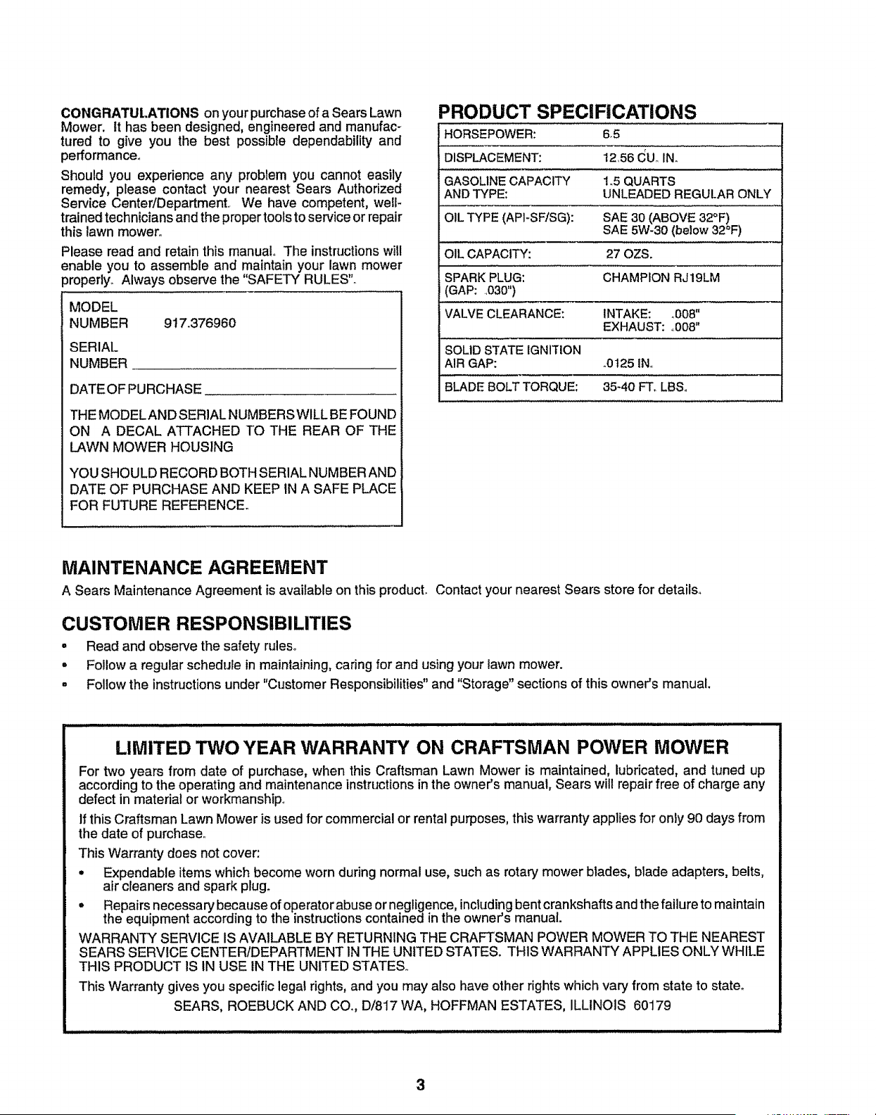
PRODUCT SPECIFICATIONS
HORSEPOWER: 6_5
DISPLACEMENT: 12_56CUoIN.
GASOLINECAPACITY 1,.5QUARTS
ANDTYPE: UNLEADED REGULARONLY
OIL TYPE (API-SF/SG): SAE 30 (ABOVE 32°F)
SAE 5W-30 (below 32°F)
OIL CAPACITY: 27 OZS.
SPARKPLUG: CHAMPION RJ19LM
(GAP: .030")
VALVECLEARANCE: INTAKE: _008"
EXHAUST: ,,008='
SOLIDSTATE IGNITION
AIR GAP: o0t25 IN,,
BLADEBOLT TORQUE: 35-40 FToLBSo
MAINTENANCE AGREEMENT
A Sears Maintenance Agreement is available on thisproduct. Contact your nearest Sears store for details°
CUSTOMER RESPONSIBILITIES
= Read and observe the safety rules°
= Follow a regular schedule in maintaining, caring for and using your lawn mower.
• Follow the instructions under "Customer Responsibilities" and "Storage" sections of this owner's manual.
............ i ii iiiwlllllll i iii iiiiiii i wl i,iLillll/l/iJlwlJill
LIMITED TWO YEAR WARRANTY ON CRAFTSMAN POWER MOWER
For two years from date of purchase, when this Craftsman Lawn Mower is maintained, lubricated, and tuned up
according to the operating and maintenance instructionsin the owner's manual, Sears will repair free of charge any
defect in material or workmanship..
If this Craftsman Lawn Mower is used for commercialor rental purposes, this warranty appliesfor only 90 days from
the date of purchase..
This Warranty does not cover:
° Expendable items which become worn during normal use, such as rotary mower blades, blade adapters, belts,
air cleaners and spark plug.
° Repairs necessary because of operatorabuse or negligence,includingbent crankshafts and the failure to maintain
the equipment according to the instructions contained in the owner's manual.
WARRANTY SERVICE IS AVAILABLE BY RETURNING THE CRAFTSMAN POWER MOWER TO THE NEAREST
SEARS SERVICE CENTER/DEPARTMENT IN THE UNITED STATES° THIS WARRANTY APPLIES ONLY WHILE
THIS PRODUCT IS IN USE IN THE UNITED STATES,,
This Warranty gives you specific legal rights, and you may also have other rights which vary from state to state°
SEARS, ROEBUCK AND CO, D/817 WA, HOFFMAN ESTATES, ILLINOIS 60179
OF CONTENTS
llll,m............................................................
SAFETY RULES ............................................................ 2
PRODUCT SPECIFICATIONS ...................................... 3
CUSTOMER RESPONSIBILITIES ..................... 3, 12-14
WARRANTY .................................................................. 3
ASSEMBLY ................................................................... 6
OPERATION .................................................................. 8
MAINTENANCE SCHEDULE ..................................... 12
SERVICE AND ADJUSTMENTS ................................ 15
STORAGE ................................................................... 16
TROUBLESHOOTING ................................................. 17
REPAIR PARTS - LAWN MOWER ........................ 18-23
REPAIR PARTS - ENGINE .................................... 25-27
PARTS ORDERING/SERVICE ................................... 28
iNDEX
A
Accessories ....................................... 5
Adjustments:
Carburetor .....................................15
Ddve Belt ............................... 15
Engine Speed ............................15
Handle Height .............................15
Height of Cut ...............................9
Air' Filter:
Replacement ........................................t4
Service ........................................14
Assembly .............................................6
B
Blade:
Sharpening ..................................13
Replacement ........................... 13
C
Controls:
Drive Control ........................................8
Engine Zone Control ....................8
Engine Speed Control .......................8
Operator Presence
Control Bar ...................................8
Customer Responsibilities ....3, 12-14
Air Filter ................................. 14
Blade Care/Replacement ....... 13
Drive Wheels ........................... 13
Engine ..................................... 14
Lubrication ....................................14
Spark Plug ..................................14
Cutting Levels ......................................9
E
Engine:
Air Filter ......................................14
Oil Change .........................................t4
Oil Level .........................................................14
Oil Type .........................................14
Starting .................................. 10
Stopping ......................................10
Storage ................................... 16
F
Fuel:
Capacity ..................................... 3
Storage ...................................................16
Type ..............................................10
H
Handle Adjustment:
Assembly ......................................6
Cutting Height ...........................15
L
Lubrication:
Engine ....................................14
Lawn Mower ..............................12
M
Maintenance Agreement ................. 3
Maintenance Schedule ................. 12
Mowing Tips.................................10
Oih
O
Engine ....................................... 12
Storage ...............................................16
Operation:
Drive Control ............................. 9
Engine Control ............................9
Grass Catcher ...............................9
Mower .............................................9
Operator Presence
Control Bar ................................................9
Options:
Accessories .......................................5
R
Repair' Parts:
Engine .................................25-27
Lawn Mower ....................... 18-23
Responsibilities, Customer.. 3, 12-14
S
Safety Rules ..................................................2
Service and Adjustrnents ...................t5
Carburetor ...........................................15
Drive Belt ...................................t5
Engine Speed ................................15
Handle ...............................................I5
Spark Plug ............................................14
Specifications ......................................3
Speed Control:
Engine ......................................... 8
Staffing the Engine ..................................10
Stopping the Engine ................................10
Storage ....................................................................16
T
Trouble Shooting Chart ...................17
W
Warranty ............................................ 3
4
LAWN MOWER ACCESSORIES
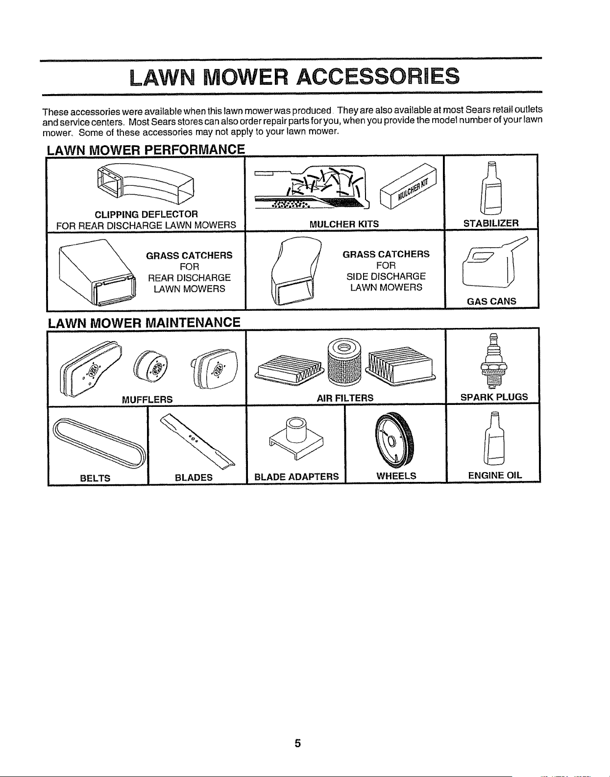
These accessories were available when this lawn mower was produced, They are also available at most Sears retail outlets
and service centers,, Most Sears stores can also order repair parts for you, when you provide the model number of your lawn
mower° Some of these accessories may not apply to your lawn mower°
LAWN MOWER PERFORMANCE
CLIPPING DEFLECTOR
FOR REAR DISCHARGE LAWN MOWERS
MULCHER KITS
GRASS CATCHERS
FOR
REAR DISCHARGE
LAWN MOWERS
S
GRASS CATCHERS
FOR
SIDE DISCHARGE
LAWN MOWERS
LAWN MOWER MAINTENANCE
BELTS
AIR FILTERS
BLADES
BLADE ADAPTERS
WHEELS
STABILIZER
GAS CANS
SPARK PLUGS
ENGINE OIL
5
llllJlljl iii
IIIIII IIIIIIIIIIIIIIIIIILII II L II L L L I
Read these instructions and this manual in its entirety
before you attempt to assemble or operate your new lawn
mower° Your new lawn mower has been assembled at the
factory with the exception of those parts left unassembled
for' shipping purposes. All parts such as nuts, washers,
bolts, etc., necessary to complete the assembly have been
placed in the parts bag. To ensure safe and proper
operation of your lawn mower, all parts and hardware you
assemble must be tightened securely. Use the correct
tools as necessary to ensure proper tightness_
TO REMOVE LAWN MOWER FROM
CARTON
• Remove loose parts included with mower:
o Cut down two end corners of carton and lay end panel
down flato
° Remove all packing materials except padding between
upper and lower handle and padding holding operator
presence control bar' to upper handle.
° Roll lawn mower out of carton and check carton thor-
oughly for' additional loose parts.
HOWTO SET UPYOUR LAWN MOWER
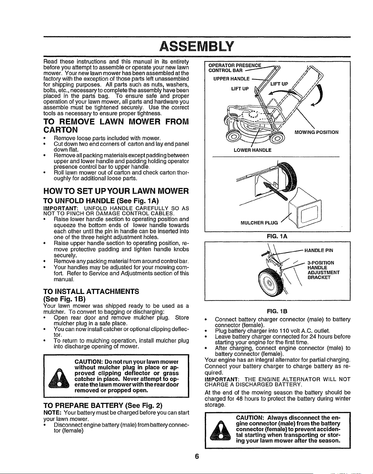
TO UNFOLD HANDLE (See Fig, 1A)
IMPORTANT: UNFOLD HANDLE CAREFULLY SO AS
NOT TO PINCH OR DAMAGE CONTROL CABLES.
• Raise lower handle section to operating position and
squeeze the bottom ends of lower handle towards
each other until the pin in handle cart be inserted into
one of the three height adjustment holes.
° Raise upper handle section to operating position, re-
move protective padding and tighten handle knobs
securely.
° Remove any packing material from around control bar'.
° Your handles may be adjusted for your mowing corn-
forty Refer to Service and Adjustments section of this
manual.
TO INSTALL ATTACHMENTS
(See Fig. 1B)
Your lawn mower was shipped ready to be used as a
mulcher: To convert to bagging or discharging:
o Open rear door' and remove mulcher plugo Store
mulcher plug ina safe place,.
° You can now install catcheror optionalclippingdeflec-
tor,_
• To return to mulching operation, install mulcher plug
into discharge opening of mower.
CAUTION: Do not run your lawn mower
without mulcher plug in place or ap-
proved clipping deflector or grass
catcher in place. Never attempt to op-
erate the lawn mower with the rear door
removed or propped open.
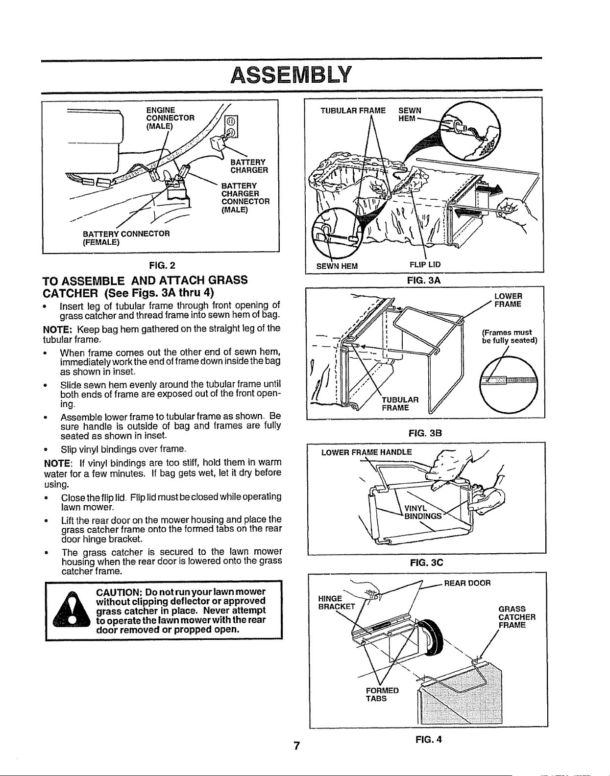
TO PREPARE BATTERY (See Fig. 2)
NOTE: Your battery must be charged before you can start
your lawn mower.
• Disconnect engine battery (male) from battery connec-
tor (female)
LY
OPERATOR PRESENCE
CONTROL BAR
UPPER HANDLE
LIFT UP
MOWING POSITION
LOWER HANDLE
MULCHER PLUG
FIG. 1A
3-POSITION
HANDLE
ADJUSTMENT
BRACKET
FIG. 1B
• Connect battery charger connector (male) to battery
connector (female),,
° Plug battery charger into 110 volt AI.C. outlet,
° Leave battery charger connected for' 24 hours before
starting your engine for the first time,,
° After charging, connect engine connector (male) to
battery connector (female).
Your engine has an integral alternator for partial charging.
Connect your battery charger to charge battery' as re-
quired_
IMPORTANT: THE ENGINE ALTERNATOR WILL NOT
CHARGE A DISCHARGED BATTERY_
At the end of the mowing season the battery should be
charged for 48 hours to protect the battery during winter
storage.
CAUTION: Always disconnect the en-
gine connector (male) from the battery
connector (female) to prevent acciden-
tal starting when transporting or stor-
ing your lawn mower after the season.
6
ENGINE
CONNECTOR
(MALE)
BATTERY CONNECTOR
(FEMALE)
BATTERY
CHARGER
BATTERY
CHARGER
CONNECTOR
(MALE)
FIG. 2
TO ASSEMBLE AND ATTACH GRASS
CATCHER (See Figs. 3A thru 4)
• Insert leg of tubular frame through front openi_ng of
grass catcher and thread frame into sewn hem Ib_ofag.
NOTE: Keep bag hem gathered on the straight leg of the
tubular frame°
• When frame comes out the other end of sewn hem,
immediately work the end of frame down inside the bag
as shown in inset,,
° Slide sewn hem evenly around the tubular frame until
both ends of frame are exposed out of the front open-
ing,,
° Assemble lower frame to tubular frame as shown° Be
sure handle is outside of bag and frames are fully
seated as shown in inset°
• Slip vinyl bindings over frame_
NOTE: If vinyl bindings are too stiff, hold them in warm
water for a few minutes_ If bag gets wet, let it dry before
using.
• Close the flip lid,. Flip lidmust be closed while operating
lawn mower,,
• Lift the rear door on the mower housing and placethe
grass catcher frame onto the formed tabs on the rear
door hinge bracket.
° The grass catcher is secured to the lawn mower
housing when the rear door is lowered onto the grass
catcher frame.
,HmHUlI, ............................
_ CAUTION: Do not runyourlawn mower
without clipping deflector or approved
grass catcher in place. Never attempt
to operatethe lawn mower with the rear
door removed or propped open.
wul,
TUBULAR FRAME SEWN
SEWN HEM
FIG, 3A
FLtP LID
LOWER
"_ _.o- / FRAME
_* _,j" _ // It (Frames must
i // 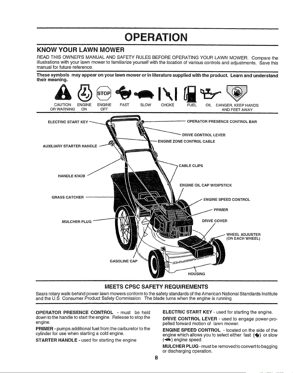
OPERATION
KNOW YOUR LAWN MOWER
READ THIS OWNER'S MANUAL AND SAFETY RULES BEFORE OPERATING YOUR LAWN MOWER. Compare the
illustrationswith your tawn mower to familiarize yoursetf with the location of various controls and adjustments_ Save this
manual for-future reference.
These symbols may appear on your lawn mower or in literature supplied with the product, Learn and understand
their' meaning.
CAUTION ENGINE ENGINE FAST SLOW CHOKE FUEL OIL DANGER, KEEP HANDS
OR WARNING ON OFF AND FEE"]' AWAY
ELECTRIC START
OPERATOR PRESENCE CONTROL BAR
AUXILIARY STARTER HANDLE
DRWECONTROLLEVER
ZONE CONTROLCABLE
HANDLEKNOB
GRASS CATCHER
CABLE CLIPS
ENGINE OIL CAP WIDIPSTICK
ENGINE SPEED CONTROL
MULCHER PLUG
DRIVE COVER
WHEEL ADJUSTER
(ON EACH WHEEL)
GASOLINE CAP
HOUSING
............... ,L,,,,,l,,l,l,,l,,,u,,,,,,,,l,,l,l,,l,,,,,, i , ,11,i, ,i / i ,, i i i Hi i i
MEETS CPSC SAFETY REQUIREMENTS
Sears rotary walk-behind power lawn mowers conform to the safety standards of the American National Standards institute
and the U_S. Consumer Product Safety Commission. The blade turns when the engine is running
OPERATOR PRESENCE CONTROL - must be held
down to the handle to start the engine.. Release to stop the
engine.
PRIMER - pumps additional fuel from the carburetor to the
cylinder for use when starting a cold engine.
STARTER HANDLE - used for starting the engine.
8
ELECTRIC START KEY _ used for starting the engine°
DRIVE CONTROL LEVER - used to engage power-pro-
pelled forward motion of lawn mower.
ENGINE SPEED CONTROL - located on the side of the
engine which allows you to seiect either fast (_) or slow
(,_m,)engine speed.
MULCHER PLUG - must be removed to convert to bagging
or discharging operation..
OPERATi
The operation of any lawn mower can result inforeign objects thrown into the eyes, which can
result in severe eye damage, Always wear safety glasses or eye shields while operating your
lawn mower or performing any adjustments or repairs, We recommend a wide vision safety
mask over the spectacles or standard safety glasses,,
HOW TO USE YOUR LAWN MOWER
CAUTION: Do not run your lawn mower
without mulcher plate inplace and door
closed orwithout an approved clipping
deflector or grasscatcher in place.
Never attempt to operate the lawn
mower with the rear door removed or
propped open.
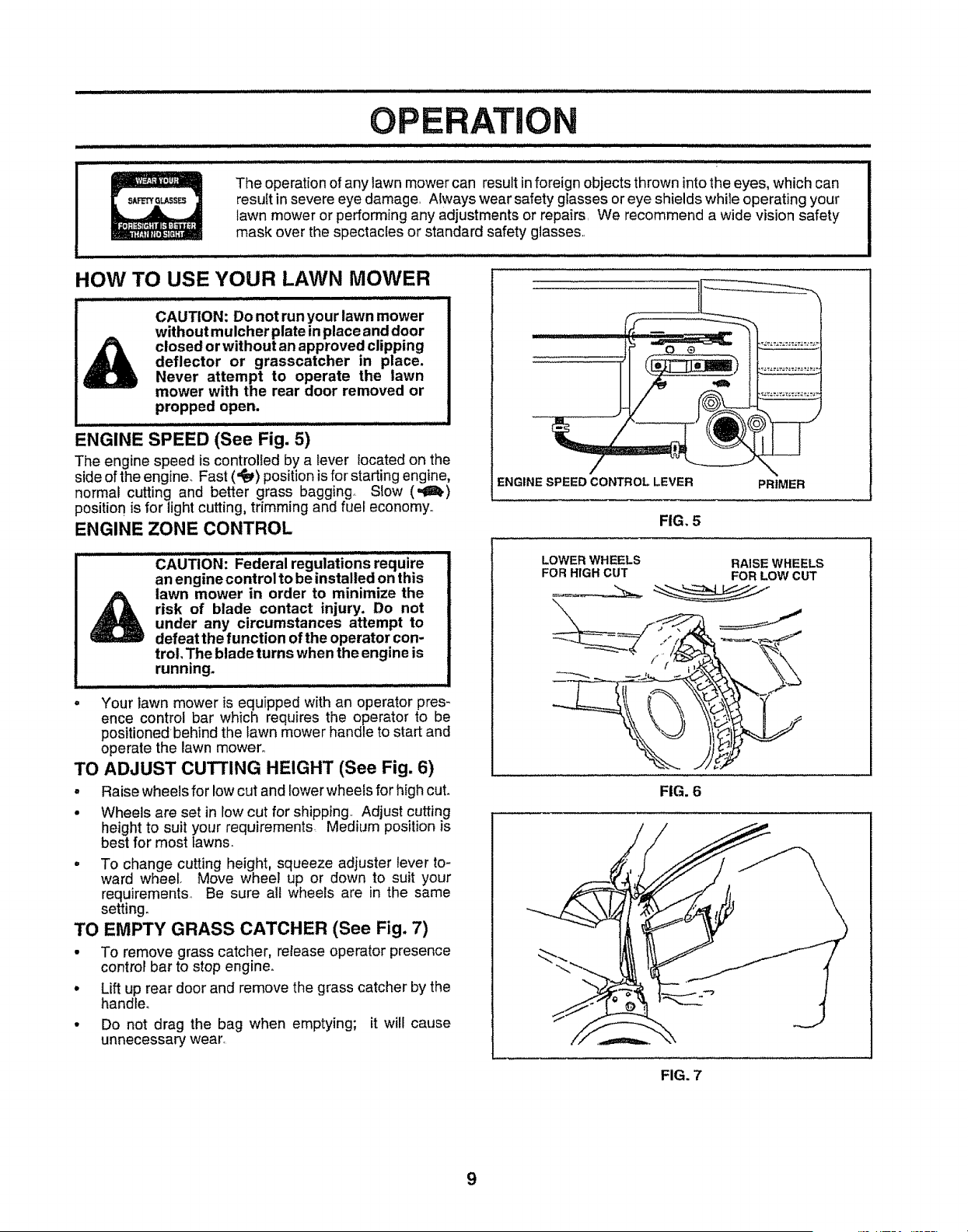
ENGINE SPEED (See Fig. 5)
The engine speed is controlled by a tever located on the
side of the engine. Fast ('_) position is for starting engine,
normal cutting and better grass bagging. Slow (,_ll.)
position is for light cutting, trimming and fuel economy.,
ENGINE ZONE CONTROL
CAUTION: Federairegulations require
an engine control to be installed on this
lawn mower in order to minimize the
risk of blade contact injury. Do not
under any circumstances attempt to
defeat the function of the operator con-
trol, The blade turns when the engine is
running,
• Your lawn mower is equipped with an operator pres-
ence control bar which requires the operator to be
positionedbehind the lawn mower handle to start and
operate the lawn mower,,
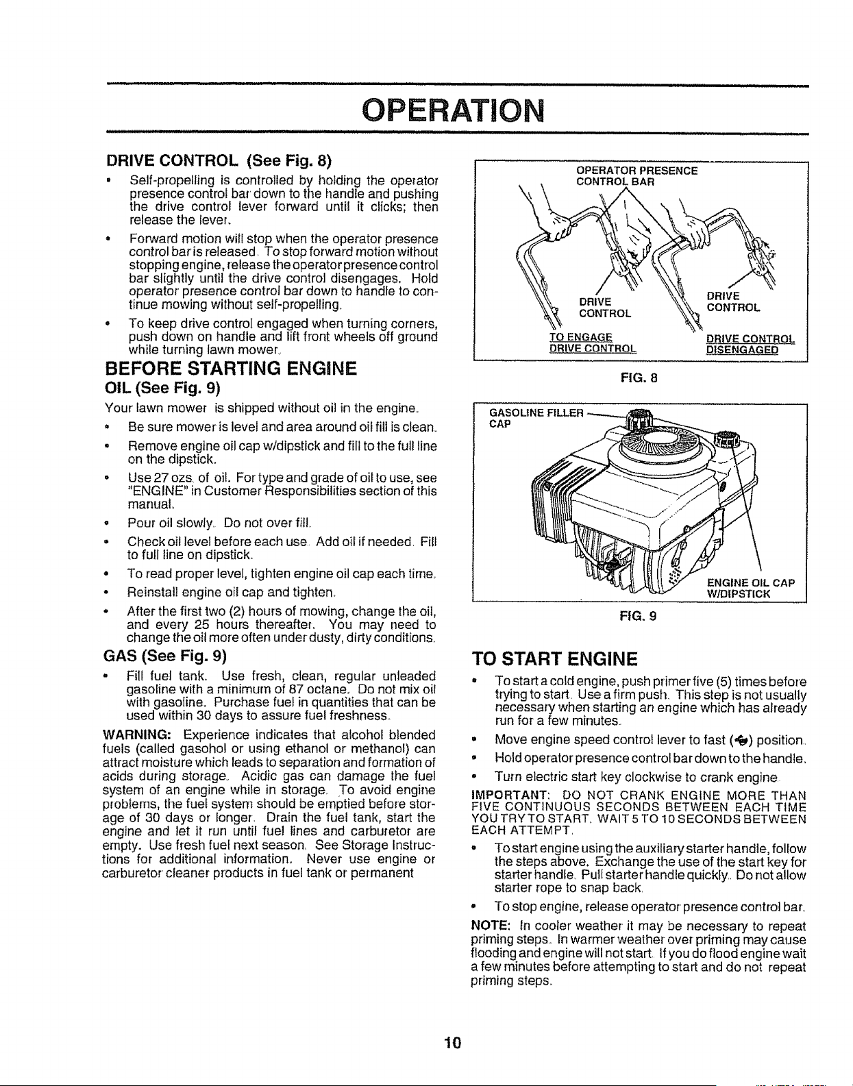
TO ADJUST CUTTING HEIGHT (See Fig. 6)
° Raise wheels for low cut and lower wheels for high cuL
° Wheels are set in low cut for shipping, Adjust cutting
height to suit your requirements. Medium position is
best for most lawns.
° To change cutting height, squeeze adjuster lever to-
ward wheel. Move wheel up or down to suit your
requirements,, Be sure all wheels are in the same
setting.
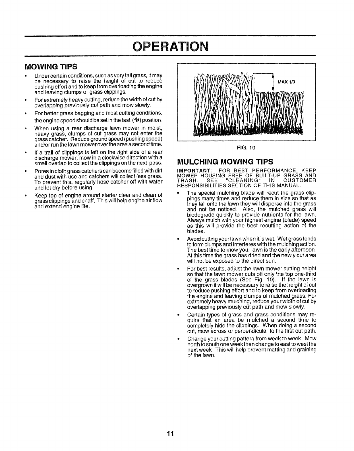
TO EMPTY GRASS CATCHER (See Fig. 7)
° To remove grass catcher, release operator presence
control bar to stop engine.,
• Lift up rear door and remove the grass catcher by the
handle°
° Do not drag the bag when emptying; it will cause
unnecessary wear,
ENGINE SPEED CONTROL LEVER PRIMER
FIG. 5
LOWER WHEELS RAISE WHEELS
FOR HIGH CUT FOR LOW CUT
FIG. 6
9
OPERAT N
DRIVE CONTROL (See Fig. 8)
• Self-propelling is controlled by holding the operator
presence control bar' down to the handle and pushing
the drive control lever forward until it clicks; then
release the lever.
• Forward motion will stop when the operator presence
control bar is released. To stop forward motion without
stopping engine, release the operator presence control
bar slightly until the drive control disengages. Hold
operator presence control bar down to handle to con-
tinue mowing without self-propelling
° To keep drive control engaged when turning corners,
push down on handle and lift front wheels off ground
while turning lawn mower_
BEFORE STARTING ENGINE
OIL (See Fig, 9)
Your lawn mower is shipped without oil in the engine..
• Be sure mower is level and area around oif fill is clean.
, Remove engine oil cap w/dipstick and fill to the full line
on the dipstick..
• Use27ozs of oil. Fortypeand grade of oii to use, see
"ENGINE" in Customer Responsibilities section of this
manual
° Pour oil slowly,, Do not over fitl,.
• Check oit leve! before each use, Add oil if needed. Flit
to full line on dipstick°
• To read proper level, tighten engine oil cap each time,.
• Reinstall engine oil cap and tighten,
• After the first two (2) hours of mowing, change the oil,
and every 25 hours thereafter_ You may need to
change the oil more often under dusty, dirty conditions,.
GAS (See Fig. 9)
• Fili fuel tank.. Use flesh, clean, regular unleaded
gasoline with a minimum of 87 octane, Do not mix oil
with gasoline., Purchase fuel in quantities that can be
used within 30 days to assure fuel freshness..
WARNING: Experience indicates that alcohol blended
fuels (called gasohol or' using ethanol or methanol) can
attract moistu re which leads to separation and formation of
acids during storage.. Acidic gas can damage the fuel
system of an engine while in storage,. To avoid engine
problems, the fuef system should be emptied before stor-
age of 30 days or longer. Drain the fuel tank, start the
engine and let it run until fuel lines and carburetor are
empty. Use fresh fuel next season, See Storage Instruc-
tions for additional information,, Never use engine or
carburetor cleaner products in fuel tank or permanent
OPERATOR PRESENCE
CONTROL BAR
FIG. 8
CAP
ENGINE OIL CAP
W!DIPSTICK
FIG. 9
TO START ENGINE
• To start a cold engine, push primer five (5) times before
trying to start. Use a firm push. This step is not usually
necessary when starting an engine which has already
run for a few minutes.
° Move engine speed control lever to fast (,_) position,,
• Hold operator presence control bar down to the handle,
° Turn electric start key clockwise to crank engine,
IMPORTANT: DO NOT CRANK ENGINE MORE THAN
FIVE CONTINUOUS SECONDS BETWEEN EACH TIME
YOUTRYTO START, WAtT5TO 10 SECONDS BETWEEN
EACH ATTEMPT,
° To start engine using the auxiliary starter' handle, follow
the steps above, Exchange the use of the start key for
starter handle, Pull starter handle quickly.. Do not allow
starter rope to snap back.
° To stop engine, release operator presence control bar,
NOTE: in cooler weather it may be necessary to repeat
priming steps., in warmer weather over priming may cause
flooding and engine will not start. Ifyou do flood engine wait
a few minutes before attempting to start and do not repeat
priming steps..
10
OPERATION
MOWING TIPS
. Under certain conditions, such as very tall grass, itmay
be necessary to raise the height of cut to reduce
pushing effort and to keep from overloading the engine
and leaving clumps of grass clipping&
• For extremely heavy cutting, reduce the width of cut by
overlapping previously cut path and mow slowly_
• For better grass bagging and most cutting conditions,
the engine speed should be set inthe fast ('_) position.
• When using a rear discharge lawn mower in moist,
heavy grass, clumps of cut grass may not enter the
grass catcher. Reduce ground speed (pushing speed)
and!or run the lawn mower over the area a second time.
, if a trail of clippings is left on the right side of a rear
discharge mower, mow in a clockwise direction with a
small overlap to collect the clippings on the next pass.
. Pores incloth grass catchers can become filled with dirt
and dust with use and catchers will collect less grass.
To prevent this, regularly hose catcher off with water
and 1etdry before using.
, Keep top of engine around starter clear and clean of
grass clippings and chaff. This will help engine air flow
and extend engine life..
MAX t/3
FIG, 10
MULCHING MOWING TIPS
IMPORTANT: FOR BEST PERFORMANCE, KEEP
MOWER HOUSING FREE OF BU1LT-UP GRASS AND
TRASH. SEE "CLEANING" IN CUSTOMER
RESPONSIBILITIES SECTION OF THtS MANUAL.
. The special mulching blade will recut the grass clip-
pings many times and reduce them in size so that as
they fall onto the lawn they will disperse into the grass
and not be noticed. Also, the mulched grass will
biodegrade quickly to provide nutrients for the lawn.
Always mulch with your highest engine (blade) speed
as this will provide the best recutting action of the
blades.
° Avoid cutting your lawn when it is wet° Wet grass tends
to form clumps and interferes with the mulching action.
The best time to mow your lawn is the early afternoon,
At this time the grass has dried and the newly cut area
will not be exposed to the direct sun°
• For best results, adjust the lawn mower cutting height
so that the lawn mower cuts off only the top one-third
of the grass blades (See Fig,. io). If the lawn is
overgrown itwilt be necessary to raise the height of cut
to reduce pushing effort and to keep from overloading
the engine and leaving clumps of mulched grass,. For
extremely heavy mulching, reduce your width of cut by
overlapping previously cut path and mow slowly..
° Certain types of grass and grass conditions may re-
quire that an area be mulched a second time to
completely hide the clippings. When doing a second
cut, mow across or perpendicular to the first cut path..
• Change your cutting pattern from week to week_ Mow
north to south one week then change to east to west the
next week This will help prevent matting and graining
of the lawn.
11
CUSTOMER RESPO LITIES
FILL IN DATES /__7
5
REGULAR SERVICE ._"__/5/_,-_._'_ j_" SERVICE DATES
Check for Loose Fasteners 61' l_ ..........
R
Clean Battery/Recharge
(Electric Start Mowers)
E €,heck Engine Oil Level t_
N Change Engine oi!
G Clean Air Filter
i Inspect Muffler
N clean or Replace Spark Plug
E, Replace Air Filter Paper Cartridge - ' :
1 - Change more often when operating under a heavy load or In high ambient temperatures.
2 _ Service more ellen when operating In dirty or dusty conditions,
3 * Replace blades more often when mowing tn sandy soiJ
4 - Charge 48 hours at end of season.
GENERAL RECOMMENDATIONS
The warranty on this lawn mower does not cover items that
have been subjected to operator abuse or negligence. To
receive full value from the warrantY, operator must maintain
mower as instructed in this manual
Some adjustments will need to be made periodically to
properly maintain your unit..
All adjustments in the Service and Adjustments section of
this manual shoutd be checked at least once each season..
° Once a year, replace the spark plug, replace air filter
element and check blade for wear,. A new spark plug
and clean/new air filter element assures proper air,fuet
mixture and helps your engine run better and last
longer,,
= Followthe maintenancescheduleinthismanual.
BEFORE EACH USE
• Check engine oil level..
• Checkfor loose fasteners.
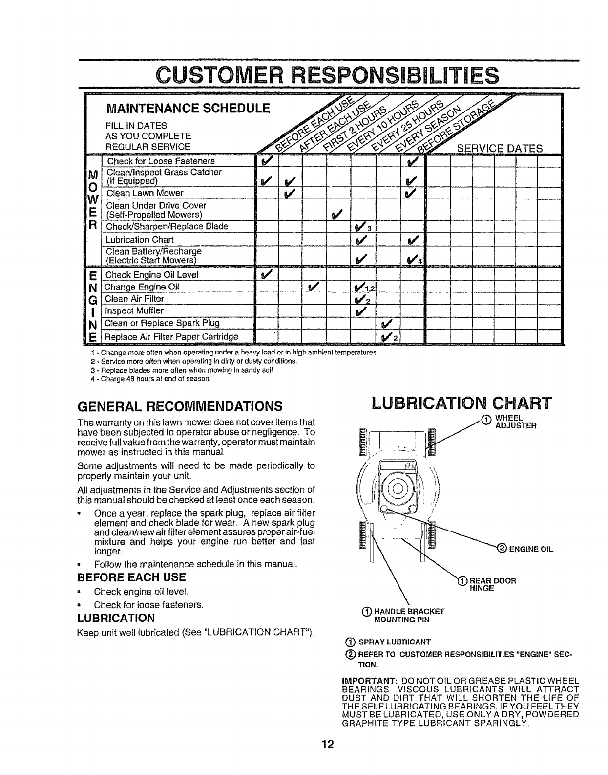
LUBRICATION
Keep unit welllubricated (See "LUBRICATION CHART").
LUBRICATION CHART
WHEEL
ADJUSTER
) ENGINE OIL
REAR DOOR
HINGE
(_ HANDLE BRACKET
MOUNTING PIN
(3) SPRAY LUBRICANT
(_ REFER TO CUSTOMER RESPONSIBILITIES "ENGINE" SEC-
TION.
IMPORTANT: DO NOT OIL OR GREASE PLASTIC WHEEL
BEARINGS, VISCOUS LUBRICANTS WILL ATTRACT
DUST AND DIRT THAT WILL SHORTEN THE LIFE OF
THE SELF LUBRICATING BEARINGS, IF YOU FEEL THEY
MUST BE LUBRICATED, USE ONLYA DRY, POWDERED
GRAPHITE TYPE LUBRICANT SPARINGLY,
12
.......................IM _ ...................
CUSTOMER R
LAWN MOWER
Always observe safety rules when performing any mainte-
nance..
TIRES
• Keep tires free of gasoline, oil, or insect control chemi-
cals which can harm rubber.
• Avoid stumps, stones, deep ruts, sharp objects and
other hazards that may cause tire damage.,
BLADE CARE
For best results, mower blade must be kept sharp.. Re-
place bent or damaged blades°
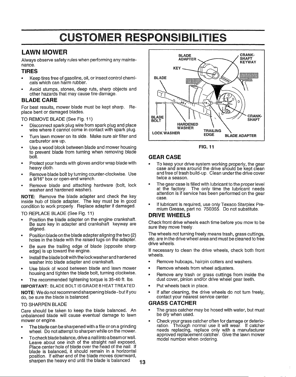
TO REMOVE BLADE (See Figo 11)
• Disconnect spark plug wire from spark plug and place
wire where it cannot come in contact with spark plug.
° Turn lawn mower on its side. Make sure air filter and
carburetor are up.
° Use a wood block between blade and mower housing
to prevent blade from turning when removing blade
boll
• Protect your hands with gloves and/or wrap blade with
heavy cloth.
• Remove blade bolt by turning counter-clockwiseo Use
a 9/16" box or open-end wrench
• Remove blade and attaching hardware (bolt, lock
washer and hardened washer)°
NOTE: Remove the blade adapter and check the key
inside hub of blade adapter. The key must be in good
condition to work properly. Replace adapter if damaged.
TO REPLACE BLADE (See Fig. 11)
• Position the blade adapter on the engine crankshaft_
Be sure key in adapter and crankshaft keyway are
aligned.
. Position blade on the blade adapter aligningthe two (2)
holes in the blade with the raised lugs on the adapter..
° Be sure the trailing edge of blade (opposite sharp
edge) is up toward the engine.
. Installthe blade boitwith the lockwasherand hardened
washer into blade adapter and crankshaft..
,, Use block of wood between blade and lawn mower
housing and tighten the blade bolt, turning clockwise°
° The recommended tightening torque is 35-40 ft.. Ibs.
IMPORTANT: BLADE BOLT IS GRADE 8 HEAT TREATED,
NOTE: We do not recommend sharpening blade- but if you
do, be sure the blade is balanced.
TO SHARPEN BLADE
Care should be taken to keep the blade balanced. An
unbalanced blade wit! cause eventual damage to lawn
mower or engine.
. The blade can be sharpened with a file or on a grinding
wheel, Do not attempt to sharpen while on the mowen
° To check blade balance, drive a nail into abeam orwallo
Leave about one inch of the straight nail exposed.
Place center hole of blade over the head of the nail. If
blade is balanced, it should remain in a horizontal
position. If either end of the blade moves downward,
sharpen the heavy end until the blade is balanced
13
BLADE
BLADE
ADAPTER
KEY
,CRANK-
SHAFT
KEYWAY
HARDENED
WASHER
TRAILING
LOCK WASHER EDGE
CRANK-
SHAFT
BLADE ADAPTER
FIG. 11
GEAR CASE
° To keep your drive system working properly, the gear
case and area around the drive should be kept clean
and free of trash build-up, Clean under the drive cover
twice a season°
- The gear case is filled with lubricant to the proper level
at the factor:/. The only time the lubricant needs
attention is if service has been performed on the gear
case.
. tf lubricant is required, use only Texaco Starplex Pre-
mium Grease, part no. 750355. Do not substitute_
DRIVE WHEELS
Check front drive wheels each time before you mow to be
sure they move freely.
The wheels not turning freely means trash, grass cuttings,
etc. are in the drive whee! area and must be cleaned to free
drive wheels..
If necessary to clean the drive wheels, check both front
wheats,.
• Remove hubcaps, hairpin cotters and washers.
• Remove wheels from wheel adjusters.
° Remove any trash or grass cuttings from inside the
dust cover, pinion and/or drive wheel gear teeth.
° Put wheels back in place,.
• If after cleaning, the drive wheels do not turn freely,
contact your nearest service center,
GRASS CATCHER
o
The grass catcher may be hosed with water, but must
be dry when used.
Check your grass catcher often for damage or deterio-
ration. Through normal use it will wear.. If catcher
needs replacing, replace only with a manufacturer
approved replacement catcher. Give the lawn mower
model number when ordering.
CUSTOMER RI
ENGINE
LUBRICATION
Use only high quality detergent oil rated with AP! service
classification SFor SG_ Select the oil's SAE viscosity grade
according to your' expected operating temperature.
SAE V]SCOSt'TY GRADES
...... I
4 llillill I;_;_13llllBIJ t
_ I 2111 l
.2o" o" 30° 32" 4o• _o" 80° _oo_
[% .3'oo ,=b" .to o o" _o" 2o"_.....................................3o- ,_o"
TEMPERATURE RANGE ANTICIPATED BEFORE NEXT OIL CHANGE
NOTE: Although multi-viscosity oils (5W30, t0W30 etc)
improve starting in cold weather, these multi-viscosity oils
will result in increased oil consumption when used above
32°F, Check your engine oil level more frequently to avoid
possible engine damage from runninglow on oil.,
Change the oil after the first two hours of operation and
every 25 hours thereafter or at least once a year if the lawn
mower is not used for-25 hours in one year.
Check the crankcase oil level before starting the engine
and after each five (5) hours of continuous use. Tighten oil
plug securely each time you check the oil level.
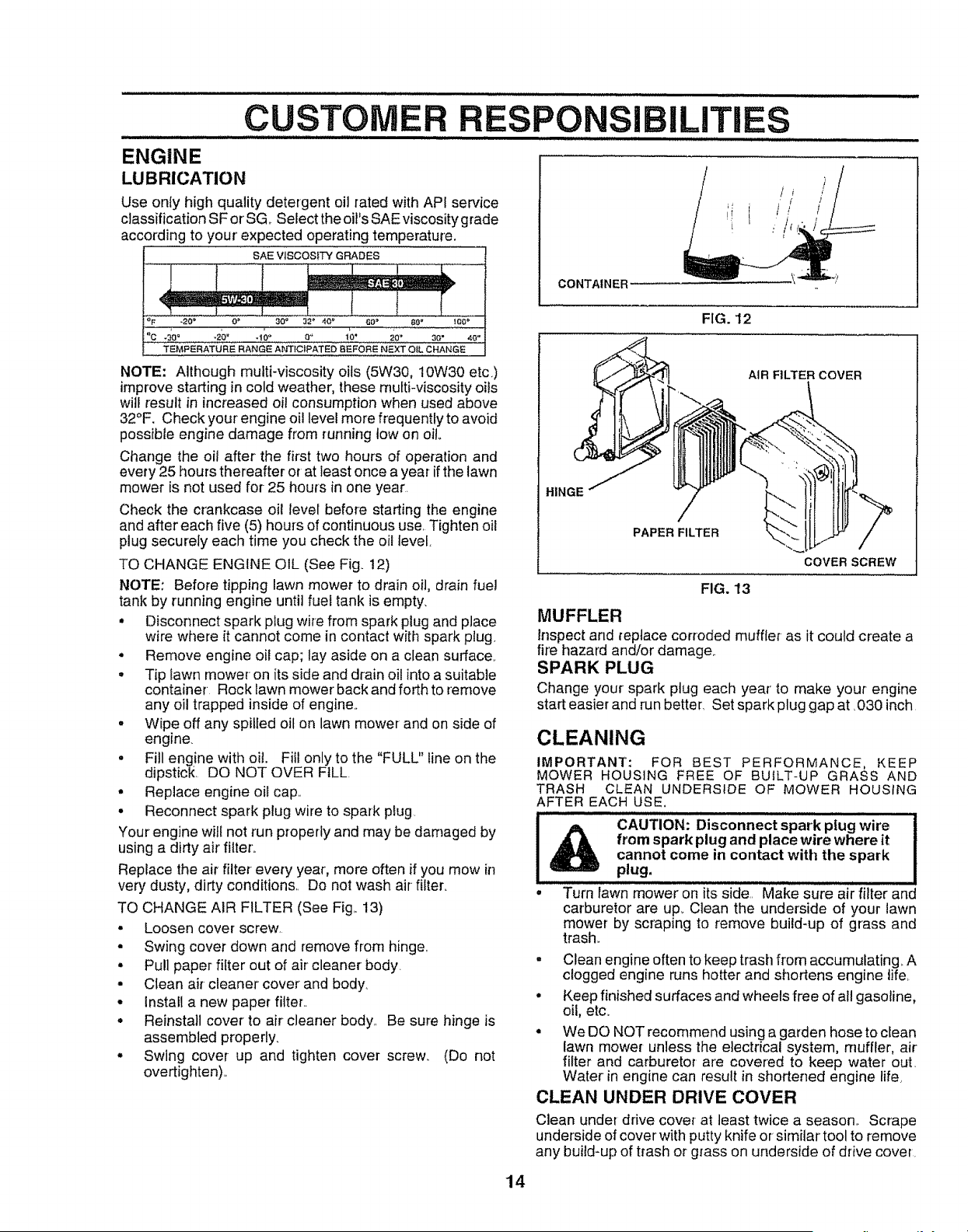
TO CHANGE ENGINE OIL (See Fig_ 12)
NOTE: Before tipping lawn mower to drain oil, drain fuel
tank by running engine until fuel tank is empty_
• Disconnect spark plug wire from spark plug and place
wire where it cannot come in contact with spark plug
• Remove engine oil cap; lay aside on a clean surface_
• Tip lawn mower on its side and drain oil into a suitable
container Rock lawn mower back and forth to remove
any oil trapped inside of engine..
• Wipe off any spilled oil on lawn mower and on side of
engine.
° Fill engine with oit. Fitl only to the "FULL" line on the
dipstick. DO NOT OVER FILL.
. Replace engine oil cap,,
• Reconnect spark plug wire to spark plug.
Your engine will not run properly and may be damaged by
using a dirty air' filter,,
Replace the air filter- every year, more often if you mow in
very dusty, dirty conditions,. Do not wash air filter,
TO CHANGE AIR FILTER (See Fig,. 13)
• Loosen cover screw.
• Swing cover down and remove from hinge,,
° Pull paper filter out of air cleaner body.
° Clean air cleaner cover and body,
• Install a new paper filter..
• Reinstall cover to air cleaner body,, Be sure hinge is
assembled properly,
° Swing cover up and tighten cover screw, (Do not
over-tighten),,
SIBILITIES
/ i
//
i
CONTAINER
FIG. 12
AIR FILTER COVER
HINGE
14
PAPER FILTER
COVER SCREW
FIG. 13
MUFFLER
Inspect and replace corroded muffler as it could create a
fire hazard and/or damage..
SPARK PLUG
Change your spark plug each year' to make your engine
start easier and run better Set spark plug gap at _030 inch
CLEANING
IMPORTANT': FOR BEST PERFORMANCE, KEEP
MOWER HOUSING FREE OF BUILT-UP GRASS AND
TRASH CLEAN UNDERSIDE OF MOWER HOUSING
AFTER EACH USE,
CAUTION: Disconnect spark plug wire
from spark plug and place wire where it
cannot come in contact with the spark
plug,
• Turn fawn mower on its side.. Make sure air filter and
carburetor are up_ Clean the underside of your lawn
mower by scraping to remove build-up of grass and
trash.,
• Clean engine often to keep trash from accumulating. A
clogged engine runs hotter and shortens engine life,
• Keep finished surfaces and wheels free of all gasoline,
oil, etc.
° We DQ NOT recommend using a garden hose to clean
lawn mower unless the electrical system, muffler, air
filter and carburetor are covered to keep water out.
Water in engine can result in shortened engine life.
CLEAN UNDER DRIVE COVER
Clean under drive cover at least twice a season.. Scrape
underside of cover with putty knife or similar tool to remove
any build-up of trash or grass on underside of drive cover.
SERVICE AND A USTMENTS
CAUTION: BEFORE PERFORMING ANY SERVICE OR ADJUSTMENTS:
o Release controlbar.
° Make sure the blade and all moving parts have completely stopped.
= Disconnect spark plug wire from spark plug and place where it cannot come in contact with plug.
LAWN MOWER
TO ADJUST CUTTING HEIGHT
See "TO ADJUST CUTTING HEIGHT" in the Operation
section of this manual,.
REAR DEFLECTOR
,The rear deflector, attached between the rear wheels of
your lawn mower, is provided to minimize the possibility
that objects wit! be thrown out the rear of the lawn mower
into the operator's mowing positlon_ If the rear deflector
becomes damaged, it should be replaced_
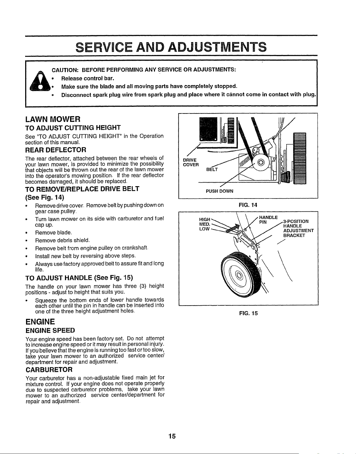
TO REMOVE/REPLACE DRIVE BELT
(See Fig, 14)
. Remove drive cover. Remove belt by pushing down on
gear case pulley..
• Turn lawn mower on its side with carburetor and fuel
cap upo
= Remove blade.
• Remove debris shield_
• Remove belt from engine pulley on crankshaft_
• Install new belt by reversing above steps.,
• Always use factory approved belt to assure fit and long
life.
TO ADJUST HANDLE (See Fig, 15)
The handle on your lawn mower has three (3) height
positions - adjust to height that suits you°
° Squeeze the bottom ends of lower handle towards
each other until the pin in handle can be inserted into
one of the three height adjustment holes.
ENGINE
ENGINE SPEED
Your engine speed has been factory set, Do not attempt
to increase engine speed or itmay result in personal injury.
Ifyou believe that the engine is running too fast or too slow,
take your lawn mower to an authorized service center/
department for repair and adjustment°
CARBURETOR
Your carburetor has a non-adjustable fixed main jet for
mixture control, if your engine does not operate properly
due to suspected carburetor problems, take your lawn
mower to an authorized service center!department for
repair and adjustment..
m
DRIVE
COVER
BELT
MP
PUSH DOWN
FIG. 14
LOW
HANDLE
PIN
HANDLE
ADJUSTMENT
BRACKET
FIG. 15
15
STORAGE
i ILl L I I
Immediately prepare your lawn mower for storage at the
end of the season or if the unit will not be used for 30 days
or more_
LAWN MOWER
When tawn mower isto be stored for a period of time, clean
it thoroughly, remove at1dirt, grease, leaves, etc. Store in
a clean, dry area.
= Clean entire lawn mower (See "CLEANING" in the
Customer Responsibilities section of this manuat).,
° Lubricate as shown in the Customer Responsibilities
section of this manual
° Be sure that all nuts, bolts, screws, and pins are
securely fastened.= Inspect moving partsfor damage,
breakage and wear. Replace if necessary_
° Touch up all rusted or chipped paint surfaces; sand
lightly before painting.
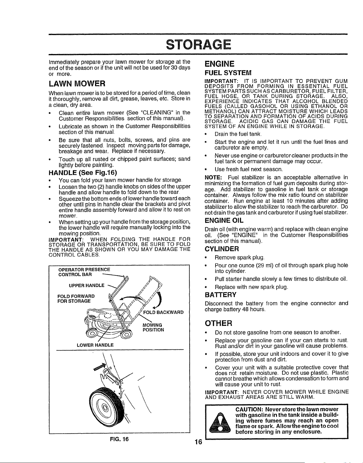
HANDLE (See Fig.16)
° You can fold your' lawn mower handle for' storage.
° Loosen the two (2) handle knobs on sides of the upper
handle and allow handle to fold down to the rear
° Squeeze the bottom ends of lower handle toward each
other until pins in handle clear the brackets and pivot
entire handle assembly forward and allow it to rest on
mower,
° When setting up your handle from the storage position,
the lower handle will require manually locking into the
mowing position.,
IMPORTANT: WHEN FOLDING THE HANDLE FOR
STORAGE OR TRANSPORTATION, BE SURE TO FOLD
THE HANDLE AS SHOWN OR YOU MAY DAMAGE THE
CONTROL CABLES
OPERATOR PRESENCE
CONTROL BAR
UPPER HANDLE
FOLD FORWARD
FOR STORAGE
FOLD BACKWARD
MOWING
POSITION
LOWER HANDLE
jJ
ENGINE
FUEL SYSTEM
IMPORTANT: IT IS IMPORTANT TO PREVENT GUM
DEPOSITS FROM FORMING IN ESSENTIAL FUEL
SYSTEM PARTS SUCH AS CARBURETOR, FUEL FILTER,
FUEL HOSE, OR TANK DURING STORAGE. ALSO,
EXPERIENCE INDICATES THAT ALCOHOL BLENDED
FUELS (CALLED GASOHOL OR USING ETHANOL OR
METHANOL) CAN ATTRACT MOISTURE WHICH LEADS
TO SEPARATION AND FORMATION OF ACIDS DURING
STORAGE. ACIDIC GAS CAN DAMAGE THE FUEL
SYSTEM OF AN ENGINE WHILE IN STORAGE..
• Drain the fuel tank,
° Start the engine and let it run until the fuel lines and
carburetor are empty.
• Never use engine or carburetorcleaner products in the
fuel tank or permanent damage may occur°
• Use fresh fuel next season_
NOTE: Fuel stabilizer is an acceptable alternative in
minimizing the formation of fuel gum deposits during stor-
age. Add stabilizer to gasotine in fuel tank or storage
container° Always follow the mix ratio found on stabilizer
container. Run engine at least t0 minutes after' adding
stabilizer to atiow the stabilizer to reach the carburetor. Do
not drain the gas tank and carburetor if using fuel stabilizer'.,
ENGINE OIL
Drain oil (with engine warm) and replace with clean engine
oil (See "ENGINE" in the Customer Responsibilities
section of this manuat)_
CYLINDER
• Remove spark plug,
° Pour one ounce (29 ml) of oil through spark plug hole
into cylinder.
• Pull starter handle slowly a few times to distribute oil.
° Replace with new spark plug.
BATTERY
Disconnect the battery from the engine connector' and
charge battery 48 hours.
OTHER
o Do not store gasoline from one season to another.
• Replace your gasoline can if your can starts to rusL
Rust and/or dirt in your gasoline will cause problems.
° If possible, store your unit indoors and cover it to give
protection from dust and dirL
° Cover your unit with a suitable protective cover that
does not retain moisture.. Do not use plastic. Plastic
cannot breathe which allows condensation to form and
will cause your unit to rust.
IMPORTANT: NEVER COVER MOWER WHILE ENGINE
AND EXHAUST AREAS ARE STILL WARM.
I CAUTION: Never store the lawn mower
I _ with gasoline in the tank inside a build-
I ,_,_, ing where fumes may reach an open
| _ flame or spark. Allowthe engineto cool
before storing in any enclosure.
I ................. iliHlli,, ....
FIG. 16 16

irnl....
TRO LESHOOTING POINTS
PROBI.EM
Does not start
Loss of power
Poor cut- uneven
Excessive vibration
Starter rope hard to pull
Loss of drive
Grass catcher not filling
(if so equipped)
Hard to push
CAUSE
1. Dirty air filter,
2 Out of fuel.
3 Stale fuel.,
4 Water in fuel
5, Spark plug wire is disconnected
6 Bad spark plug
7 Loose blade or broken bfade adapter
8. Control bar tn released position
9 Control bar defective
t0 Weak battery,
11, Disconnected battery connector.
CORRECTION
1, Cteardreplace air filter
2, Fill fuel tank
3 Drain tank and refill with fresh clean fuel
4, Drain fuel tank and carburetorand refi]l tank with fresh
gasoline,
5. Connect wire to plug
6. Replace spark plug,,
7 Tighten blade bolt or replace blade adapter,
8 Depress control bar tohandle
9 Replace control bar,
I0. Charge battery,
11. Connect battery to engine
1 Rear of lawn mower housingtblade dragging
in heavy grass.
2 Cutting too much grass,
3 Dirty air filter
4 Buildup of grass, leaves and trash under mower,
5. Too much oilin engine,
6 Walking speed too fast,
1 Worn, bent or !oose blade
2 Wheet heights uneven
3 Low eng{ne speed
4., Buildup of grass, leaves, and trash under mower,
1 Worn, bent or Ioose blade
2 Bent engine crankshaft,
I. Engine flywheel brake is on when control bar is
released.
2. Bent engine crankshaft
3 Blade adapter broken.
4. Blade dragging in grass.
1 Ddve wheels not turning with dr_ve centre! engaged
2 Belt not driving,
1. Cutting height tootow
2. Lift on blade worn off.
3 Catcher not venting air.
4 Low engine speed
!, Grass is too high or wheel height is too low,
2 Rear of lawn mower housing/blade dragging
in grass
3 Grass catcher too full,
4 Handte height position not right for you.,
illl i ill i iillll uu
1. Set fn "Higher Cut" position,,
2, Set in "Higher Cut" positlon_
3. Clean!rep{ace air filter
4 Clean underside of mower housing,
5, Check eli level
6 Cut at slower walking speed
ijll i u,i,i,,, Hill, i ii L
1 Replace blade Tighten blade bolt.
2. Set all wheels at same height
3, Set engine speed control in fast position
4, Clean underside of mower housing
=,,=,,i,,1,Ni =,l= ILl I
1. Replace blade Tighten blade bolt
2 Contact authorized service center/department,
1 Depress control bar to upper handle before
puflingstarter rope,
2 Contact authorized service center/depadment
3 Replace blade adapter.
4. Move lawn mower to cut grass or to hard surface
to start engine
1 Adjust or replace drive control cable, if broken
2 Put belt on pulleys or reptace belts if broken
t, Raise cutting height
2 Replace biade
3 Clean grass catcher,,
4 Set engine speed control in fast posiiton,
I Raise cutting height
2 Raise rear of lawn mower housing one (1)
setting higher
3, Empty grass catcher
4., Adjust handle height to suit.
17
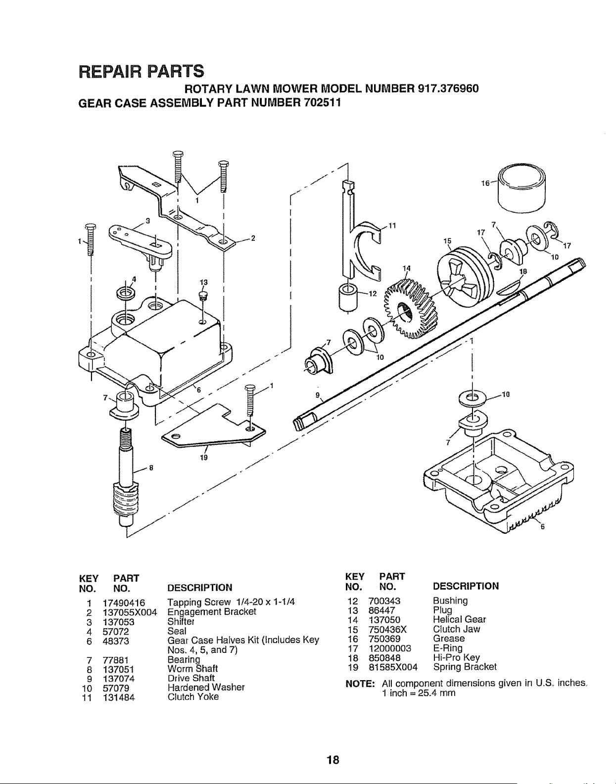
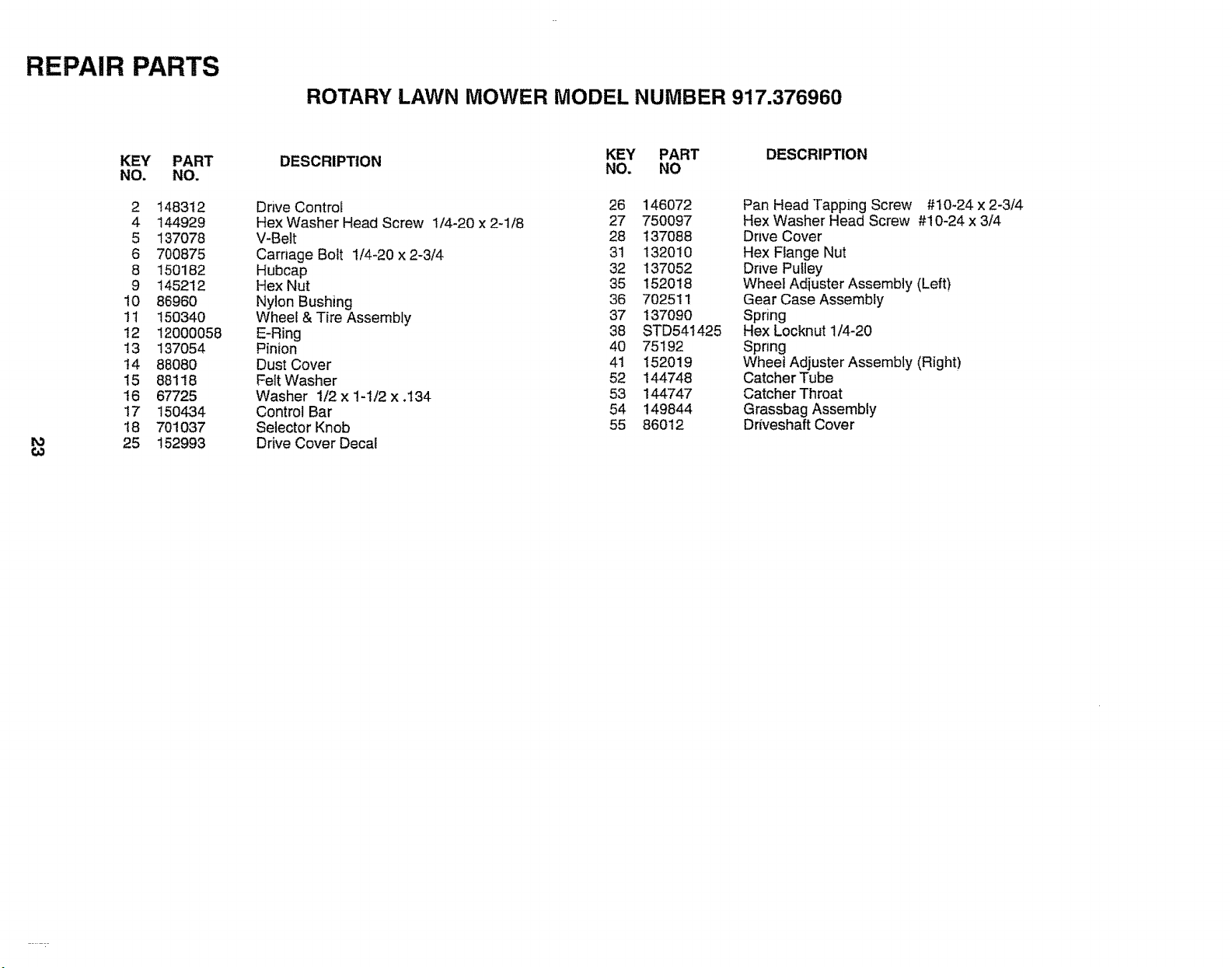
REPAIR PARTS
ROTARY LAWN MOWER MODEL NUMBER 917.376960
GEAR CASE ASSEMBLY PART NUMBER 702511
_J
J
15
7
t7
KEY
NO.
1
2
3
4
6
7
8
9
10
1!
PART
NO.
17490416
137055X004
137053
57072
48373
77881
137051
137074
57079
131484
DESCRIPTION
Tapping Screw 1/4-20 x 1-t/4
Engagement Bracket
Shifter
Seal
Gear Case Halves Kit (Includes Key
No& 4, 5, and 7)
Bearing
Worm Shaft
Drive Shaft
Hardened Washer
Clutch Yoke
KEY PART
NO. NO. DESCRIPTION
12 700343 Bushing
13 86447 Plug
14 137050 Helical Gear
15 750436X Clutch Jaw
t6 750369 Grease
17 12000003 E-Ring
18 850848 Hi-Pre Key
19 81585X004 Spring Bracket
NOTE: All component dimensions given in U_Soinche&
1 inch = 2&4 mm
18

REPAIR PARTS
ROTARY LAWN MOWER MODEL NUMBER 917.376960
4
2
f
7
3
5
\
8
6
KEY
NO.
1
2
3
4
5
6
7
8
PART
NO.
86334X479
86337X479
750909
750097
86353
1t1549X
86649
134861
DESCRIPTION
Battery Bracket
Battery Cover
Battery
Hex Washer Head Screw
# 10-24 xl/2
Connector Mounting Clip
Battery Charger
Battery Pad
Battery Wrap
19
REPAIR PARTS
ROTARY LAWN MOWER MODEL NUMBER 917.376960
27
25
13
26
1
\
29
28
8
4\
<
31
3O
72
|
!
is J
4O
55
31
35
26
\
28
29
47
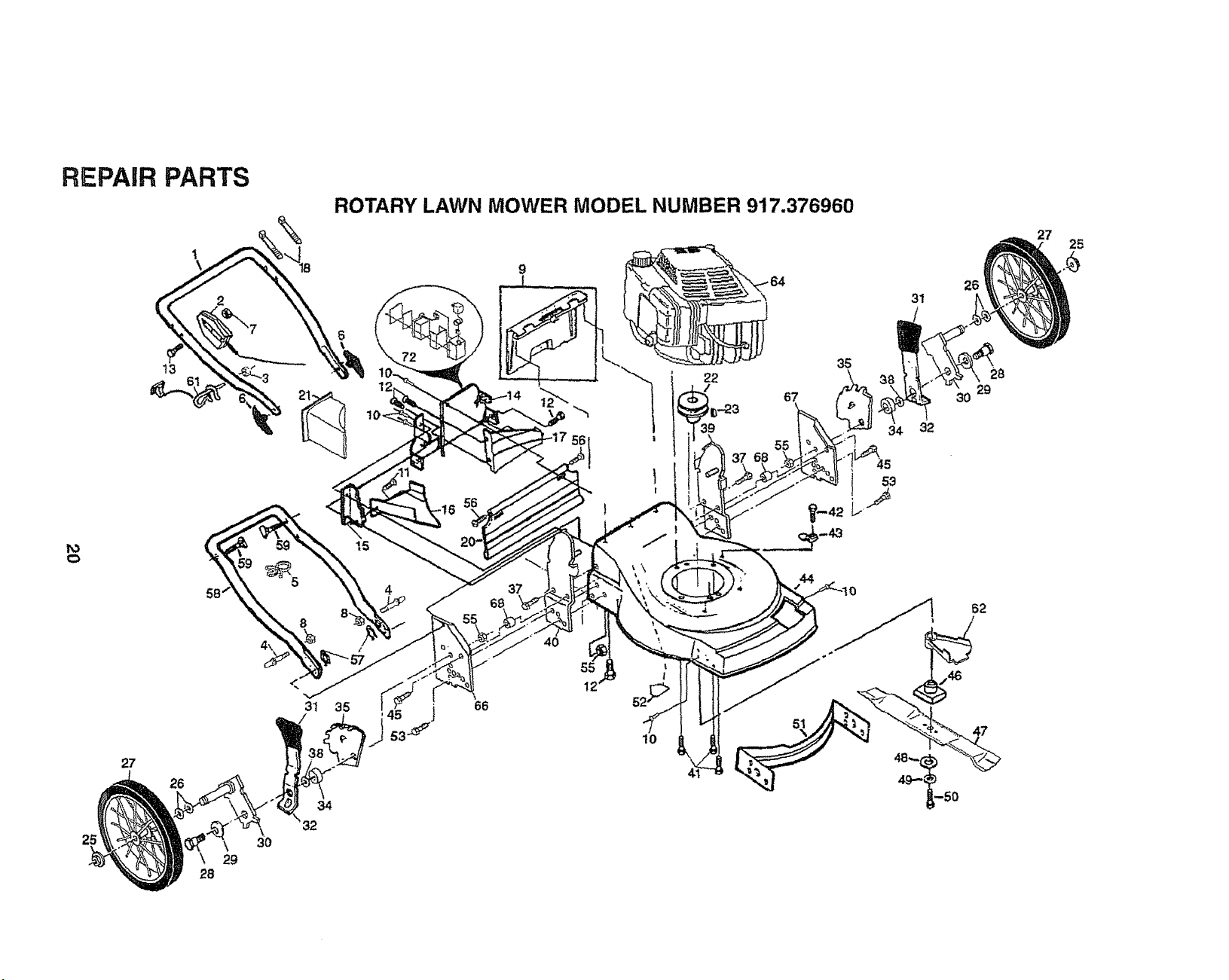
REPAIR PARTS
ROTARY LAWN MOWER MODEL NUMBER 917.376960
KEY PART
NO. NO
1 149637X479
2 151501
3 73510400
4 150502
5 151517
6 136376
7 STD541425
8 73990500
9 147612
10 128415
11 150050
t2 STD512505
13 144929
14 700494X479
t5 700365X479
16 133190X479
17 t40661X479
18 66426
20 140540
21 150425
22 85543
23 87677
25 83923
26 57143
27 151160
28 142748
29 61651
30 7509t3X004
31 701037
32 700331X004
34 146630
35 750085X007
37 55187
DESCRIPTION
Upper Handle
Engine Zone Control Cable
Keps Nut
EZ Adiust Handle Bolt
Cable Clip
Handle Knob
Locknut 1/4-20
Nut
Rear Door Kit
Pop Rivet
Self Tapping Screw #10-24
Hex Tapping Screw 1/4-20 x 1/2
Hex Washer Head Screw 1/4-20 x 2-1/8
Back Plate
Side Baffle
Discharge Baffle
Rear Baffle
Wire, Tie
Rear Skirt
Mulcher Plug
Engine Pulley
Hi-Pro Key #505
Nut
Washer
Wheel & Tire Assembly
Shoulder Bolt 3/8-16
Bellevilfe Washer
Axle Arm Assembly
Selector Knob
Selector Spring
Spacer
Wheel Adiusting Bracket
Thread Cutting Screw 5/16-18 x 3/4
KEY PART DESCRIPTION
NO. NO
38 88348
39 153131X479
40 153130X479
41 150406
42 750097
43 87930
44 48410
45 149588
46 851514
47 141114
48 851074
49 850263
50 851084
51 700869X479
52 85463
53 74760612
55 751592
56 88652
57 51793
58 151723X479
59 131959
61 132001
62 134612
64 152842
66 700170X479
67 700172X479
68 86969
72 ......
-- 153596
Washer
Handle Bracket Assembly (Left)
Handle Bracket Assembly (Right)
Hex Head Thread Rolling Screw 3/8-16 x 1-1/8
Hex Washer Head Screw #10-24 x 1/2
Guide Clip
Lawn Mower Housing (Incl. Key #14,15, 17, 51 & 52)
Screw
Blade Adapter
Blade 22"
Hardened Washer
Helical Washer 3/8-24 x 1-3/8 Grd. 8
Hex Head Machine Screw 3/8-24 x 1-3/8 Grd. 8
Front Baffle
Danger Decal
Bolt
Locknut 3/8-16
Hinge Screw
Hairpin Cotter
Lower Handle
Handle Bolt
Rope Guide
Debris Shield
Engine - Craftsman - Model No. 143.966506
Support Bracket (Right)
Support Bracket (Left)
Spacer
See Battery Repair Parts Page
Owner's Manual (English/Spanish)
Available accessories not included with lawn mower:.
7__!.133623 Gas Can (2.5 gal.)
71 33500 Fuel Stabilizer
7._!!33027 SAE 30W Oil (27 oz.)
7__$133417 Dust Shield
7_!133316 Mower Cover
7_!33303 Chute Deflector
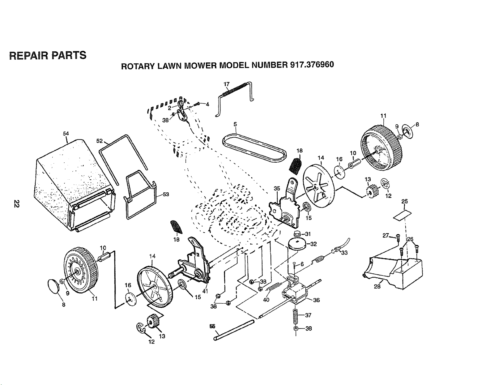
REPAIR PARTS
ROTARY LAWN MOWER MODEL NUMBER 917.376960
17
54
\
tt
18
14
15
12
13
10
14 16
11
12
25
!
REPAIR PARTS
ROTARY LAWN MOWER MODEL NUMBER 917.376960
to
KEY PART
NO. NO.
2 148312
4 144929
5 137078
6 700875
8 150182
9 145212
10 86960
11 150340
12 12000058
i3 137054
14 88080
15 88118
16 67725
17 150434
18 701037
25 152993
KEY PART DESCRIPTION
DESCRIPTION NO. NO
Drive Control 26 146072
Hex Washer Head Screw 1/4-20 x 2_1/8 27 750097
V-Belt 28 137088
Carnage Bolt 1/4-20 x 2-3/4 31 132010
Hubcap 32 137052
Hex Nut 35 152018
Nylon Bushing 36 702511
Wheel & Tire Assembly 37 137090
E-Ring 38 STD541425
Pinion 40 75192
Dust Cover 41 152019
Felt Washer 52 144748
Washer 1/2 x 1-1/2 x .134 53 144747
Control Bar 54 149844
Selector Knob 55 86012
Drive Cover Decal
Pan Head Tapping Screw #10-24 x 2-3/4
Hex Washer Head Screw #10-24 x 3/4
Drive Cover
Hex Flange Nut
Drive Pulley
Wheel Adiuster Assembly (Left)
Gear Case Assembly
Spring
Hex Locknut 1/4-20
Spring
Wheet Adjuster Assembly (Right)
Catcher Tube
Catcher Throat
Grassbag Assembly
Driveshaft Cover
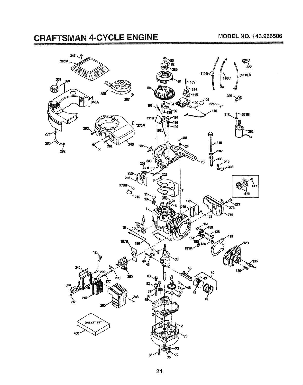
CRAFTSMAN 4-CYCLE ENGINE MODELNO.143.966506
301 300
416
41
i
I I
I
24
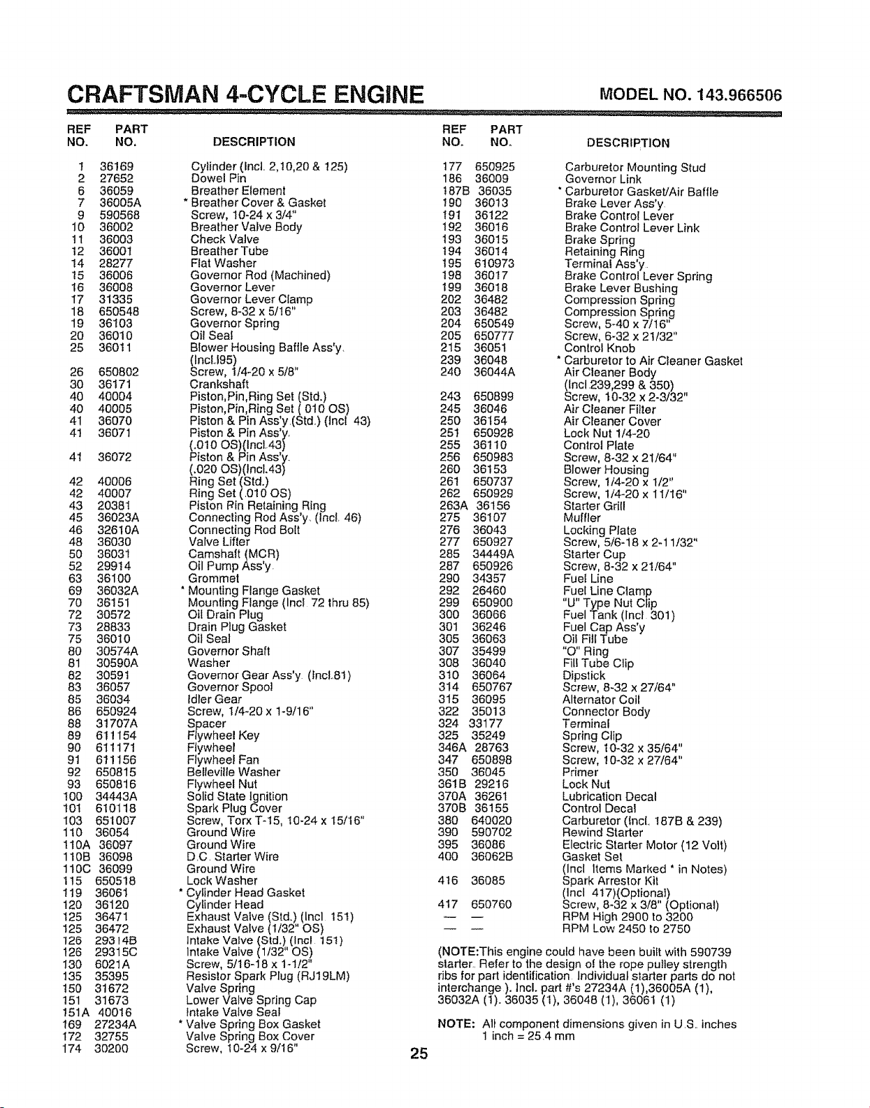
CRAFTSMAN 4-.CYCLE ENGINE MODELNO.143.966506
REF PART REF PART
NO. NO. DESCRIPTION NO. NO. DESCRIPTION
1 36169 Cylinder (Incl.. 2,t0,20 & 125) t77 650925 Carburetor Mounting Stud
2 27652 Dowel Pin 186 36009 Governor Link
6 36059 Breather Element !87B 36035 * Carburetor Gasket/Air Baffle
7 36005A * Breather Cover & Gasket 190 36013 Brake Lever Ass'y
9 590568 Screw, 10-24 x 3/4" i91 36122 Brake Control Lever
10 36002 Breather Valve Body 192 36016 Brake Control Lever Link
1t 36003 Check Valve t93 36015 Brake Spring
!2 36001 Breather Tube 194 360t4 Retaining Ring
14 28277 Flat Washer !95 610973 Terminal Ass'y
t5 36006 Governor Rod (Machined) t98 360t7 Brake Control Lever Spring
t6 36008 Governor Lever 199 360t8 Brake Lever Bushing
17 31335 Governor Lever Clamp 202 36482 Compression Spring
18 650548 Screw, 8-32 x 5/I6" 203 36482 Compression Spring
19 36103 Governor Spring 204 650549 Screw, 5_40 x 7/16"
20 36010 Oil Seat 205 650777 Screw, 6-32 x 21/32"
25 360tl Blower Housing Baffle Ass'y 215 36051 Control Knob
(IncU95) 239 36048 * Carburetor to Air CIeaner Gasket
26 650802 Screw, !/4-20 x 5/8" 240 36044A Air Cleaner Body
30 36171 Crankshaft (Incl 239,299 & 350) ,,
40 40004 Piston,Pin,Ring Set (Std.) 243 650899 Screw, 10-32 x 2-3/32
40 40005 Piston, Pin,Ring Set (010 OS) 245 36046 Air Cleaner Filter
41 36070 Piston & Pin Ass'y(Std.) (tncl 43) 250 36154 Air Cleaner Cover
41 36071 Piston & Pin Ass'y. 251 650928 Lock Nut 1/4-20
(.010 OS)(1ncl.43) 255 36110 Control Plate
4t 36072 Piston & Pin Ass'y.. 256 650983 Screw, 8-32 x 21/64"
(.020 OS)(lncL43) 260 36t53 Blower Housing
Screw, 1/4-20 x t/2"
42 40006 Ring Set (Std.) 261 650737
42 40007 Ring Set (.010 OS) 262 650929 Screw, 1/4-20 x 11/t6"
43 20381 Piston F_inRetaining Ring 263A 36156 Starter Grill
45 36023A Connecling Rod Ass'y_ (lncl. 46) 275 36t07 Muffler
46 326t0A Connecting Rod Bolt 276 36043 Locking Plate
48 36030 Valve Lifter 277 650927 Screw, 5/6-18 x 2-11/32"
50 36031 Camshaft (MCR) 285 34449A Starter Cup
52 29914 Oil Pump Ass'y 287 650926 Screw, 8-32 x 2t/64"
63 36100 Grommet 290 34357 Fuel Line
69 36032A ' Mounting Flange Gasket 292 26460 Fue[ Line Clamp
70 36151 Mounting Flange (Incl 72 thru 85) 299 650900 "U"Type Nut Clip
72 30572 Oil Drain Plug 300 36066 Fuel Tank (lncl 30t)
73 28833 Drain Plug Gasket 301 36246 Fuel Cap Ass'y
75 36010 Oil Seal 305 36063 Oil Fill Tube
80 30574A Governor Shaft 307 35499 "O" Ring
81 30590A Washer 308 36040 FilITube Clip
82 3059t Governor Gear Ass'y (fncL81) 3t0 36064 Dipstick
83 36057 Governor Spool 314 650767 Screw, 8-32 x 27/64"
85 36034 idler Gear 315 36095 Alternator Colt
86 650924 Screw, I/4-20 x 1-9/16" 322 35013 Connector Body
88 31707A Spacer 324 33177 Terminal
89 611154 Flywheel Key 325 35249 Spring Clip
90 6Ilt7t Flywheel 346A 28763 Screw, 10-32 x 35/64"
91 61! 156 Flywhee! Fan 347 650898 Screw, 10-32 x 27/64"
92 650815 Bel_eville Washer 350 36045 Primer
93 650816 Flywheel Nut 361B 29216 Lock Nut
!00 34443A Solid State Ignition 370A 36261 Lubrication Decal
t01 610118 Spark Plug Cover 370B 36155 Control Decal
I03 651007 Screw, Torx T-t5, t0-24 x t5/16" 380 640020 Carburetor ({ncL 187B & 239)
110 36054 Ground Wire 390 590702 Rewind Starter
110A 36097 Ground Wire 395 36086 Electric Starter Motor (12 Volt)
110B 36098 D.C Starter Wire 400 36062B Gasket Set
110C 36099 Ground Wire (Incl Items Marked ' in Notes)
1t5 650518 Lock Washer 4t6 36085 Spark Arrestor Kit
119 36061 * Cytinder Head Gasket (Incl 417)(Optiona0
120 36120 Cylinder Head 4t7 650760 Screw, 8-32 x 3/8" (Optional)
125 36471 Exhaust Valve (Std.) (tncl 15t) RPM High 2900 to 3200
t25 36472 Exhaust Valve (t/32" OS) RPM Low 2450 to 2750
126 293t#B Intake Valve (Std,) (Incl t51)
t26 29315C Intake Valve (1t32" OS) (NOTE:This engine could have been built with 590739
130 6021A Screw, 5/16-18 x 1-1/2" starter.. Refer to the design ol the rope pulley strength
135 35395 Resistor Spark Plug (RJ19LM) ribs for part identification Individual starter parts do not
t50 31672 Valve Spring interchange ). Incl. part #'s 27234A (1),36005A (1),
t51 31673 Lower Valve Spring Cap 36032A (t). 36035 (1), 36048 (1), 36061 (1)
151A 40016 intake Valve Seal
169 27234A * Valve Spring Box Gasket NOTE: Alt component dimensions given in U.S.. inches
I72 32755 Valve Spring Box Cover t inch = 25.4 mm
174 30200 Screw, t0-24 x 9/16" 25
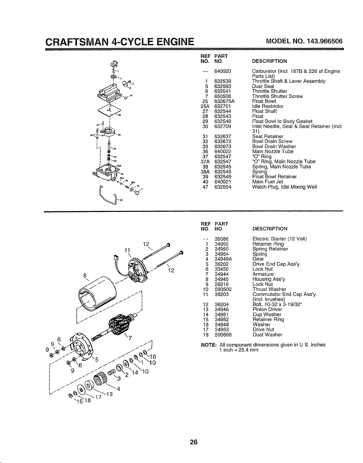
CRAFTSMAN 4-CYCLE ENGINE MODELNO.143.966506
• ,_,j_:_ ..........-:........ .....................
REF PART
NO+ NO+ DESCRIPTION
640020 Carburetor (lncl 187B & 239 of Engine
Parts List)
1 632539 Throttle Shaft & Lever Assembly
5 632593 Dust Seat
6 632541 Throttle Shutter
7 650506 Throttle Shutter Screw
25 632675A Float Bowl
25A 632701 Idle Restrictor
27 632544 Float Shaft
28 632543 Float
29 632548 Float Bowl to Body Gasket
30 632709 Inlet Needle, Seat & Seat Retainer (tncl
31)
31 632637 Seat Retainer
32 632672 Bowl Drain Screw
33 632673 Bowl Drain Washer
36 640022 Main Nozzle Tube
37 632547 "O" Ring
37A 632547 "O" Ring, Main Nozzle Tube
38 632545 Spdng, Main NozzieTube
38A 632545 Spring
39 632549 Float Bowl Retainer
40 640021 Main Fuel Jet
47 632554 Welch Plug, Idle Mixing Well
11
REF PART
NO. NO+ DESCRIPTION
-- 36086 Electric Starter (12 Volt)
1 34955 Retainer Ring
2 34950 Spring Retainer
3 34954 Spring
4 34949A Gear'
5 36202 Drive End Cap Ass'y.
6 33450 Lock Nut
7 34944 Armature
8 34945 Housing Ass'y
9 29216 Lock Nut
10 590500 Thrust Washer
tl 36203 Commutator End Cap Ass'y.
(lncl. brushes)
12 36204 Bolt, 10+32 x 349/32"
13 34946 Pinion Driver
14 34951 Cup Washer
15 34952 Retainer Ring
16 34948 Washer
17 34953 Drive Nut
18 590608 Dust Washer
NOTE: All component dimensions given in U S. inches
1 inch = 25.+4mm
26
CRAFTSMAN 4-CYCLE ENGINE MODELNO.143.966506
O_2
REF PART
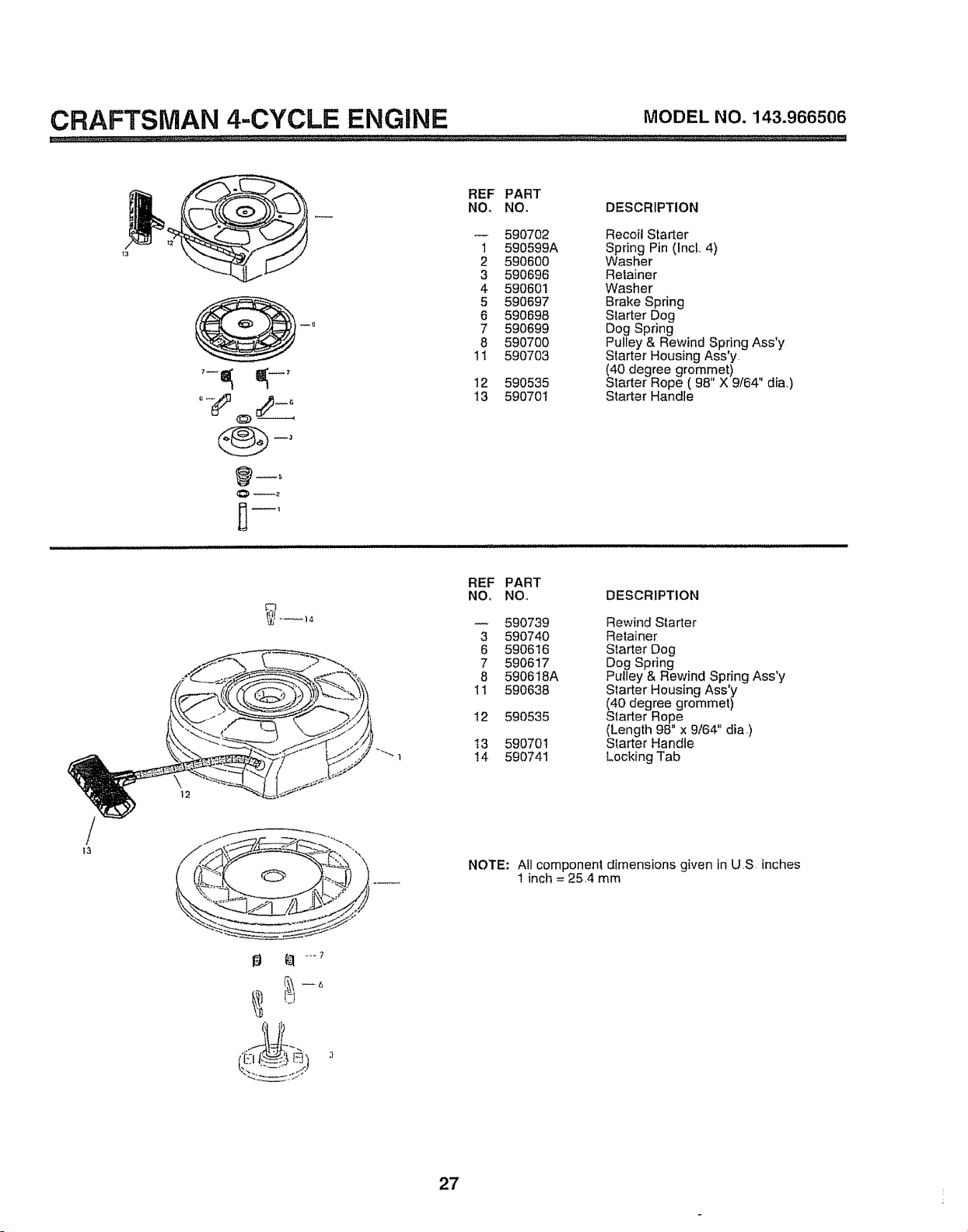
NO, NO. DESCRIPTION
590702 Recoil Starter
1 590599A Spring Pin (IncL 4)
2 590600 Washer
3 590696 Relainer
4 590601 Washer
5 590697 Brake Spring
6 590698 Starter Dog
7 590699 Dog Spring
8 590700 Pulley & Rewind Spring Ass'y
11 590703 Starter Housing Assy
(40 degree grommet)
12 590535 Starter Rope ( 98" X 9/64" dia,,)
13 590701 Starter Handle
REF PART
NO. NO,, DESCRIPTION
590739 Rewind Starter
3 590740 Retainer
6 590616 Starter Dog
7 590617 Dog Spring
8 590618A Pulley & Rewind Spring Ass'y
I1 590638 Starter Housing Ass'y
(40 degree grommet)
12 590535 Starter Rope
(Length 96" x 9/64" dia.)
t3 590701 Starter Handie
t4 590741 LockingTab
t3
NOTE: All componen! dimensions given in US inches
1 inch = 25,4 mm
27
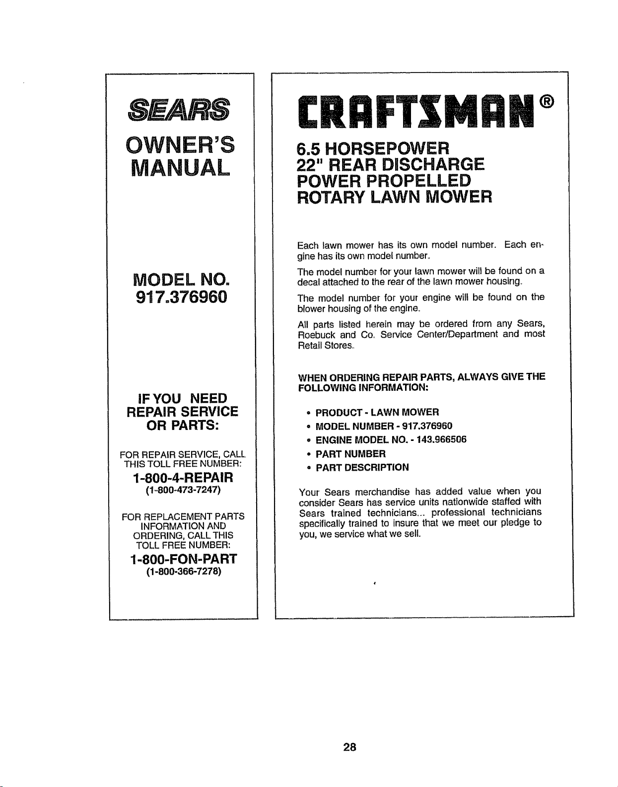
OWNER'S
MANUAL
MODEL NO.
917o376960
IF YOU NEED
REPAIR SERVICE
OR PARTS:
FOR REPAIR SERVICE, CALL
THIS TOLL FREE NUMBER:
1-800-4-REPAIR
(1-800-473-7247)
FOR REPLACEMENT PARTS
INFORMATION AND
ORDERING, CALL THIS
TOLL FREE NUMBER:
1-800-FON-PART
(1-800-366-7278)
MAN+
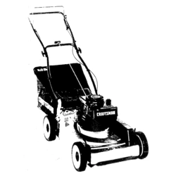
6.5 HORSEPOWER
22" REAR DISCHARGE
POWER PROPELLED
ROTARY LAWN MOWER
Each lawn mower has its own model number. Each en-
gine has its own model number.,
The model number for' your lawn mower will be found on a
decal attached to the rear'of the lawn mower housing°
The model number for your engine will be found on the
blower housing of the engine.
All parts listed herein may be ordered from any Sears,
Roebuck and Co, Service Center/Department and most
Retail Stores,.
WHEN ORDERING REPAIR PARTS, ALWAYS GIVE THE
FOLLOWING INFORMATION:
• PRODUCT- LAWN MOWER
,, MODEL NUMBER - 917.376960
o ENGINE MODEL NO. - 143.966506
" PART NUMBER
° PART DESCRIPTION
Your Sears merchandise has added value when you
consider Sears has service units nationwide staffed with
Sears trained technicians.., professional technicians
specifically trained to insure that we meet our ptedge to
you, we service what we sell
28
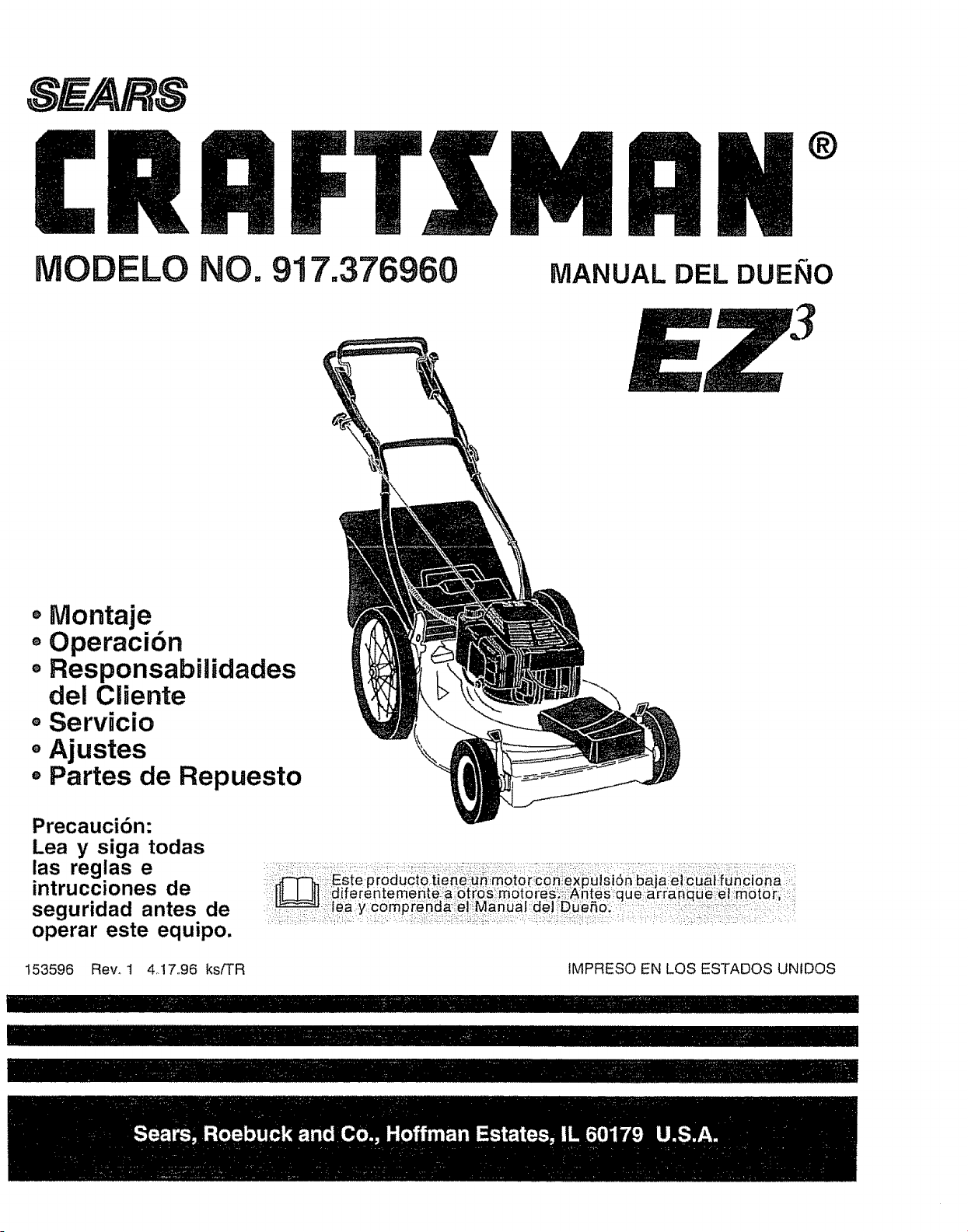
DELO NO. 917.376960
MIIII °
MANUAL DEL DUENO
, Montaje
+ Operaci6n
= ResponsabBlidades
del Cliente
o Servicio
• Ajustes
- Partes de Repuesto
Precaucibn:
Lea y siga todas
las reglas e
intrucciones de
seguridad antes de ............
operar este equipo.
153596 Rev. 1 4+17+96 ksfTR IMPRESO EN LOS ESTADOS UNIDOS
l ...................II iiiiiiiiiiiiiiiiiiiiiiiiiiiiiiiiiiii
I1+11111!!1!111'11+iiiiiiiiiiiiiiiiiiiiiiiiiiiiiiiiiii.....
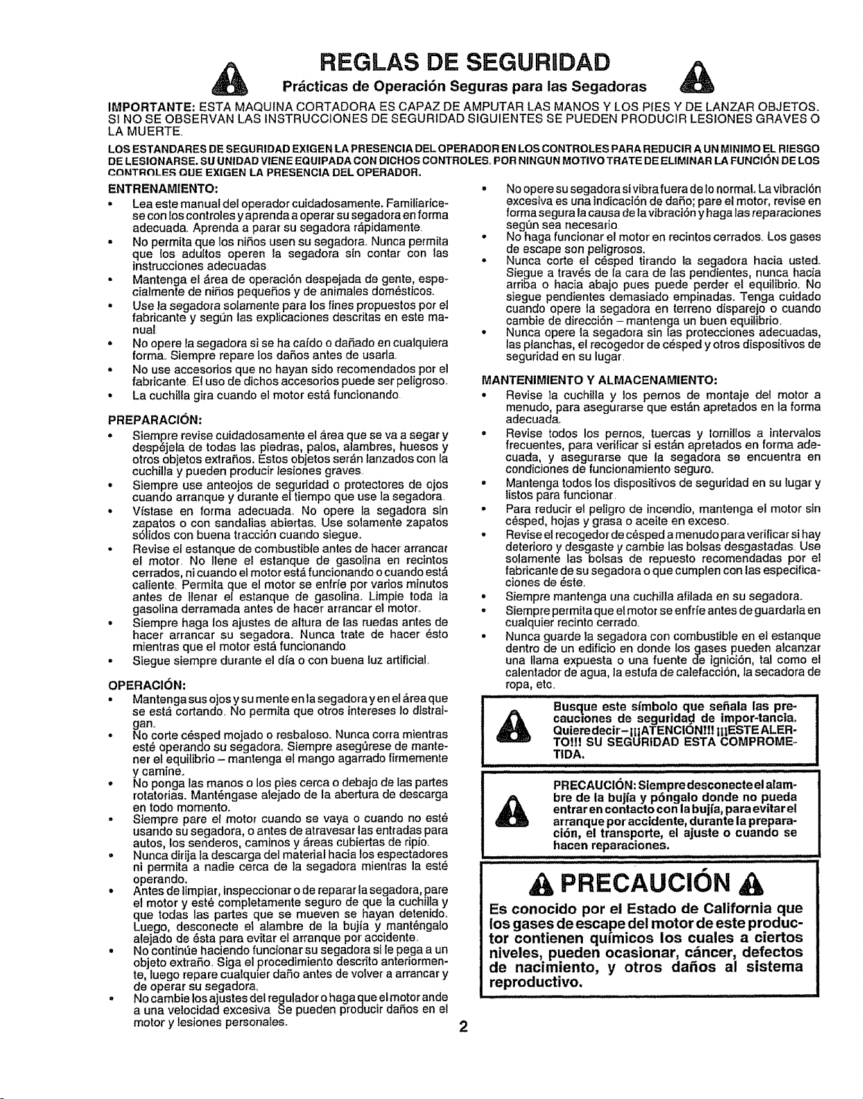
REGLAS DE SEGURUDAD
Pr,_cticas de Operaci6n Seguras para las Segadoras
IMPORTANTE: ESTA MAQUINA CORTADORA ES CAPAZ DE AMPUTAR LAS MANES Y LOS PIES Y DE LANZAR OBJETOS.
SI NO SE OBSERVAN LAS INSTRUCCtONES DE SEGURIDAD SIGUIENTES SE PUEDEN PRODUCIR LESIONES GRAVES O
LA MUERTE
LOS ESTANDARES DE SEGURIDAD EXIGEN LA PRESENCIA DELOPERADOR EN LOS CONTROLES PARA REDUCIR A UN MINIMO EL RIESGO
DE LESIONARSE. SL! UNtDAD VIENE EQUIPADA CON DICHOS CONTROLES_ PeR NINGUN MOTIVe TRATE DE ELIMINAR LA FUNCI(3N DE LOS
COktTR_LER QUE EXIGIEN LA PRESENCIA DEL OPERADOR.
ENTRENAMIENTO:
° Lea este manual del operador cuidadosamente_ Familiarice-
se con los controles yaprenda a operar su segadora en forma
adecuada_ Aprenda a parar su segadara r_pldamente
= No permita que los niSos usen su segadora. Nunca permita
que los adultos operen la segadora sin contar con las
instrucciones adecuadas
• Mantenga el _rea de operaci6n despejada de genre, espe-
cia[mente de niSos pequeSos y de animales dom6sticos.
• Use la segadora sotamente para los fines propuestos per et
fabricante y segQn las expiicaciones descritas en este ma-
nual
= No opere la segadora si se ha ca[do o daSado en cualquiera
forma. Siempre repare los daSos antes de usarla.
• No use accesodos que no hayan side recomendados per el
fabricante EI use de dichos accesorios puede ser peligroso._
• La cuchilla gira cuando el motor est_ funcionando.
PREPARACION;
• Siempre revise cuidadosamente el area que se va a segar y
desp_jela de todas las piedras, palos, alambres, huesos y
otros objetos extra_.os. Estos objetos set'An lanzados con la
cuchilta y pueden producir lesiones graves.
° Siempre use anteojos de seguridad o protectores de ojos
cuando arranque y durante eltiempo que use la segadora.
• Vfstase en forma adecuada, No opere la segadora sin
zapatos o con sandalias abiertas. Use solamente zapatos
s61idos con buena tracci6n cuando siegue.,
• Revise el estanque de combustible antes de hacer arrancar
el motor. No tlene el estanque de gasot}na en recintos
cerrados, ni cuando el motor est& funcionando o cuando est&
caliente. Permita que el motor se enfrie per varies minutes
antes de tlenar el estanque de gasolina., Limpie toda la
gasolina derramada antes de hacer arrancar el motor..
= Siempre haga los ajustes de altura de las ruedas antes de
hacer arrancar su segadora. Nunca trate de hacer 6sto
mientras que el motor est,. funcionando.
- Siegue siempre durante el di'a o con buena luz artificial,
OPERACION:
° Mantengasus ojos ysu menteen la segadorayen el _rea que
se est,_cortando. No permita que otros intereses lo dlstraJ-
gan.
• No corte c_sped mojado o resbaloso. Nunca corra mientras
est_ operando su segadora,. Siempre aseg_rese de mante-
her el equitibrio - mantenga et mango agarrado firmemente
y camineo
° No ponga las manas o los pies cerca o debajo de las partes
rotatorias. Mant6ngase atejado de la abertura de descarga
en todo memento.
- Stempre pare e! motor cuando se vaya o cuando no est_
usando su segadora, o antes de atravesar las entradas para
autos, los senderos caminos y ,_reas cubiertas de ripio.
• Nunca dirija ta descarga del material hacia los espectadores
ni permita a nadie cerca de la segadora mientras la est_
operando. , .
• Antes de limpiar, inspeccionar o de reparar la segaaot'a, pare
el motor y est6 compietamente seguro de clue la cuchiita y
que todas las partes que se mueven se hayan detenido.
Luego desconecte et atambre de la bujia y mant6ngalo
atejado de 6sta para evitar el arranque per accidente.
° No continue haciendo funcienar su segadora sile pega a un
objeto extraSo. Siga el procedimiento descrito anteriormen-
to, luego repare cualquier dafio antes de votver a arrancar y
de operar su segadora,
• No cambie losajustes del regulador o hagaque el motor ande
a una ve!ocidad excesiva. Se pueden produeirdaSos en el
motor y lesiones personales.,
• No opere su segadora si vibra fuera de 1onormal. La vibractSn
excesiva es una indicaci6n de daSo; pare el motor, revise en
forma segura la causa de la vibracibn y haga las reparaciones
seg_in sea necesario
• No haga funcionar el motor en recintos cerrados_ Los gases
de escape son peligrosos.
• Nunca corte el c_sped tirando la segadora hacia usted.
Siegue a trav6s de la cara de Ias pendientes, nunca haeia
arriba o hacia abajo pues puecle perder el equilibrio. No
siegue pendientes demasiado empinadas. Tonga cuidado
cuando opere la segadora en te_]'enodisparejo o cuando
cambie de direcci6n - mantenga un buen equiJibrio.
° Nunca opere la segadora sin las protecciones adecuadas,
lasplanchas, el recogedor de c_sped y otros disposit[vos de
seguridad en su lugar.
MANTENIMIENTO Y ALMACENAMIENTO:
• Revise la cuchitla y los pemos de montaje del motor a
menudo, para asegurarse que est&n apretados en la forma
adecuada..
° Revise lodes los pernos, tuercas y torn|lies a intervalos
frecuentes, para verificarsi est_n apretados en forma ade-
cuada, y asegurarse que la segadora se encuentra en
tend|clones de funcionamiento seguro_
• Mantenga todos los dispositivos de seguridad en su lugar' y
I{stospara funcionar.
• Para reducir el peligro de incendio, mantenga el motor sin
c_sped, hojas y grasa o aceite en exceso.
• Revise el recogedor de c_sped a menudo para verificar si hay
deterioro y desgaste y cambie las bolsas desgastadas. Use
solamente las botsas de repuesto recomendadas per el
fabricante de su segadora o que cumplen con las especifica-
ciones de 6ste.
° Siempre mantenga una cuchilla afilada en su segadora.
• 8iempre permita que et motor se enfrie antes de guardarla en
cualquier recinto cerrado.
• Nunca guarde la segadora con combustible en el estanque
dentro de un edificio en donde los gases pueden alcanzar
una llama expuesta o una fuente de ignici6n, tal come el
calentador de agua, ia estufa de calefacci6n, la secadora de
ropa, etc.
Quieredecir- IIiATENCiONtI! |tIESTE ALER-
TO!!1 SU SEGURIDAD ESTA COMPROME -
TIDA.
PRECAUClON: Siempre desconecte el alam-
bre de la bujia y p6ngalo donde no pueda
entrar en contacto con la buj{a, para evitar el
arranque per accidenf, e, durante la prepara-
ci6n, el transporte, el ajuste o cuando se
hacen reparaciones.
PRECAUCION A
Es conocido per el Estado de California que
los gases de escape del motor de este produc-
tor contienen qu/micos los cuales a ciertos
niveles, pueden ocasionar, c_ncer, defectos
de nacimiento, y otros da_os al sistema
reproductive.
.................................. i,i
2
FELICITACIONES per tacompra desu segadora Sears Craftsman..
Ha side disefiada, planificada y fabricada para darie la mejor
confiabilidad y el mejor rendimiento posibles
En e! case de que se encuentre con cualquier problema que no
pueda solucionar f_cttmente, haga el favor de ponerse en contac-
to con su Centro/Departamento de Servicio Sears m&s cercano.
Sears cuenta con t_cnicos bien capacitados y competentes y con
tas herramientas adecuadas para darle servicio o para reparar su
unidad..
H_g_ el f_vor d_ I_._r y rl_. OEtnrd_r P.._I_,manH_l. Estas instruccio-
nes le perm_tir_n montar y mantener su segadora en forma
adecuada Siempre observe las "REGLAS DE SEGURIDAD"
NUMERO DE
MODELO 917.376960
NUMERO DE
SERIE
FECHA DE
COMPRA
EL NUMERO DEL MODELO Y EL DE SERIE SE ENCUEN-
TRAN EN LA CALCOMANIA ADJUNTA A LA PARTE TRA-
SERA DE LA CAJA DE LA SEGADORA._
DEBE REGISTRAR TANTO EL NUMERO DE SERIE COMe
LA FECHA DE COMPRA Y MANTENGALOS EN UN LU-
GAR SEGURO PARA REFERENCIA EN EL FUTURe.
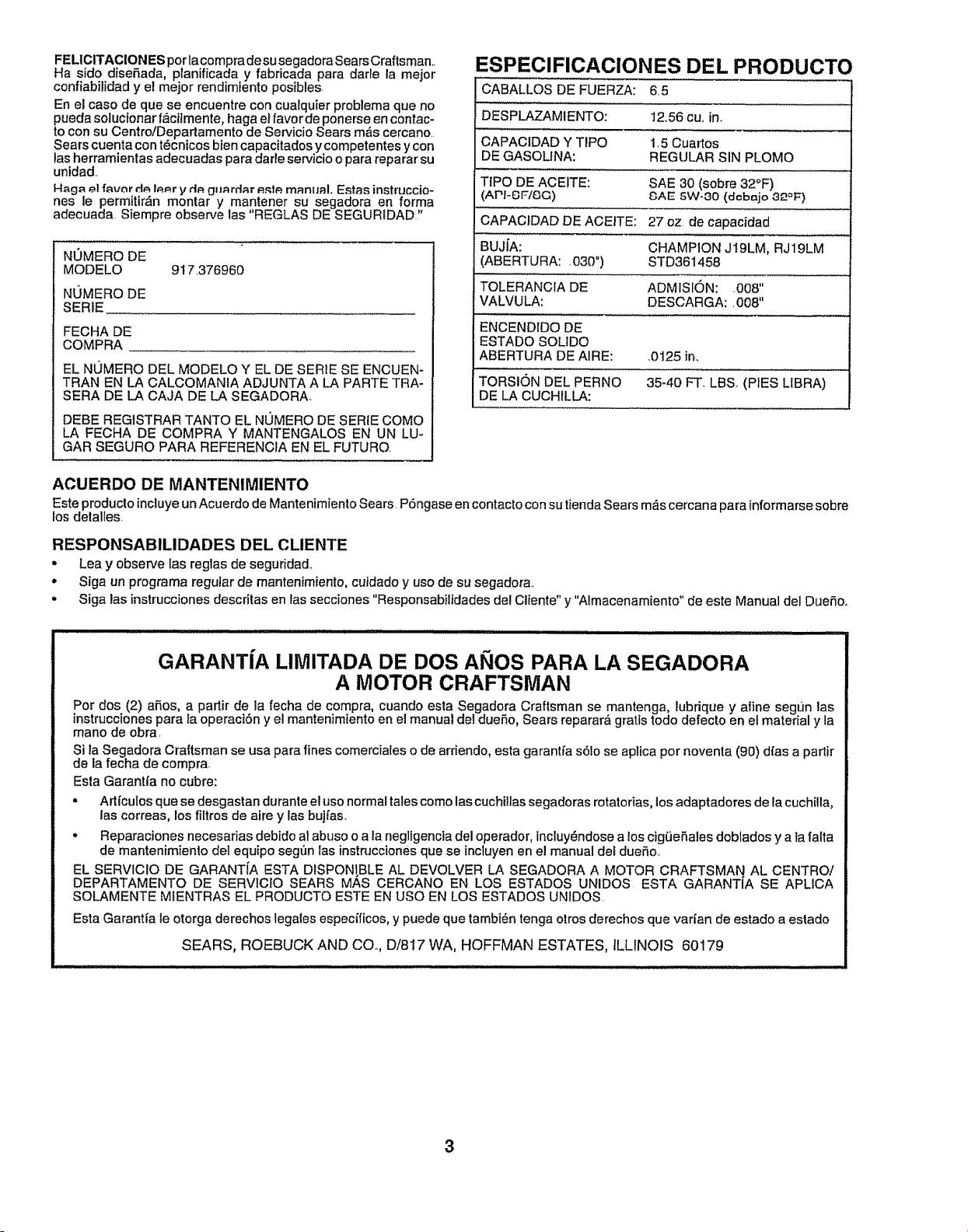
ESPECIFICACIONES DEL PRODUCTO
CABALLOS DE FUERZA: 6.5
DESPLAZAMIENTO: 1256 cu.. in.
CAPAClDAD Y TIPO 1,5 Cuartos
DE GASOLtNA: REGULAR SIN PLOMO
TIPO DE ACEITE: SAE 30 (sobre 32°F)
(API-BF/SQ) _AE 5W-80 (dobajo ,32oF)
CAPACIDAD DE ACEITE: 27 oz. de capacidad
BUJiA: CHAMPION J19LM, RJ19LM
(ABERTURA: ,030") STD361458
TOLERANCIA DE ADMISION: 008"
VALVULA: DESCARGA;. 008"
ENCENDIDO DE
ESTADO SOLIDO
ABERTURA DE AIRE: .0t25 in.
TORSION DEL PERNO 35-40 FT. LBS (PIES LIBRA)
DE LA CUCHtLLA:
ACUERDO DE MANTENIMIENTO
EsteproductoincluyeunAcuerdo deMantenimientoSears. P6ngaseencontactoconsu tiendaSearsm_scercanaparainformarsesebre
los detalles
RESPONSABILIDADES DEL CLIENTE
o Lea y observe las regias de seguridad,
• Siga un programa regular de mantenimiento, cuidado y use de su segadora..
,, Siga las instrucciones descritas en tas secciones "Responsabilidades del Cliente" y "Almacenamiento" de este Manual del DueSo.
GARANT(A LIMITADA DE DOS AI IOS PARA LA SEGADORA
A MOTOR CRAFTSMAN
Per dos (2) aries, a partir de la fecha de compra, cuando esta Segadora Craftsman se mantenga, tubrique y afine segun las
instrucciones para Ia operaciSn y el mantenimtento en el manual de1dueSo, Sears reparar_ gratis todo defecto en el material y la
mane de obra.
Si la Segadora Craftsman se usa para fines comerciales o de arriendo, esta garantfa s61ose aplica per noventa (90) dias a partir
de la fecha de compra.
Esta Garantfa no cubre:
,' Artl'culos que se desgastan durante el use normal tales come las cuchitlassegadoras rotatorias, los adaptadores de la cuchilla,
las correas, los filtros de aire y las bujfas.
• Reparaciones necesarias debido al abuse o a la negllgencla del operador, incluy_ndose a los cigLiefiales doblados y a la falta
de mantenimiento del equipo seg_'mtas instn_cciones que se incluyen en el manual dei duefio
EL SERVICIO DE GARANTiA ESTA DISPON!BLE AL DEVOLVER LA SEGADORA A MOTOR CRAFTSMAN AL CENTRe/
DEPARTAMENTO DE SERVlClO SEARS MAS CERCANO EN LOS ESTADOS UNIDOS ESTA GARANTIA SE APLICA
SOLAMENTE MIENTRAS EL PRODUCTO ESTE EN use EN LOS ESTADOS UNIDOS
Esta Garantia le otorga derechos legales espec[ficos, y puede que tambi_n tenga otros derechos que varian de estado a estado
SEARS, ROEBUCK AND CO,, D/817 WA, HOFFMAN ESTATES, ILLINOIS 60179
3
TABLA ATER
REGLAS DE SEGURIDAD ............................................ 2
ESPECIFICACIONES DEL PRODUCTO ..................... 3
RESPONSABILIDADES DEL CLIENTE ........... 3, 10-12
GARANTfA .................................................................... 3
MONT_JE; ...................................................................... 6
OPERACION .............................................................. 7-9
PROGRAMA DE MANTENIMIENTO .......................... 10
SERVICIO Y AJUSTES ............................................... 14
ALMACENAMIENTO ................................................... 15
IDENTIFICACION DE PROBLEMAS ......................... 16
PARTES DE REPUERTO ... VEA LA SECCI6N INGLI_S
ORDEN DE PARTES/SERVICIO ................................ 20
iNDICE
A
Aceite:
Almacenamiento ............................. 15
Motor ..................................................12
Acuerdo de mantenimiento .....................t0
Ajustes:
Altura de corte .....................................8
Altura del mango ...................................14
Carburador .......................................................14
Cable de control de impulsi6n .......13
Velocidad del motor' .................................14
Almacenamiento ........................................15
Arranque del motor ..........................................9
B
Bujia ........................................................................I2
C
Combustible:
Aimacenamiento .............................15
Capacidad .......................................................9
Tipo ...........................................................9
Controles:
Barra de control que exige ta
presencia del operador ..................7
Control do la impulsi6n .........................8
Control de la velocidad del motor _.8
Control de la zona del motor ..............8
Consejos para segar .....................................9
Cuchilla:
Afilamiento .............................................11
Cambio ..........................................................1t
E
Especificaciones ...............................................3
F
Filtro de Aire:
Servicio ..............................................12
G
Garantia ......................................................3
L
Lubricaci6n:
Motor .......................................................12
M
Mango:
Ajuste ...............................................................14
Montaje ................................................6
Montaje .........................................................6
Motor:
Almacenamiento ..............................15
Arranque .............................................9
Cambio de aceite ..............................t2
Filtro de aire ................................................12
Nivel de aceite ............................................12
Parada .........................................................9
Tipo de aceite .......................................12
N
Niveles de corte ...........................................8
O
Opciones:
Accesorios ..........................................5
Operaci6n:
Barra de controlque exige la
presencia del operador .......................7
Control de la impulsi6n .......................8
Control del motor .......................................8
Recogedor de c6sped ...........................11
P
Parada del motor. ..............................................9
Programa de mantenimiento ..................10
R
Reglas de seguridad ...............................................
Responsabilidades del Cliente ....3, 10-12
Bujia ..........................................................12
Cuidado de la cuchillafcambio .......11
Filtro de abe .....................................12
Lubricaci6n .............................................10
Motor ........................................................12
Ruedas de imputsi6n ..........................11
S
Servicio y Ajustes:
Carburador ....................................................14
Control de impulsi6n ...............................8
Mango ....................................................14
Velocidad del motor ................................14
T
Tabla para la identificaci6n de
problemas .....................................................16
4
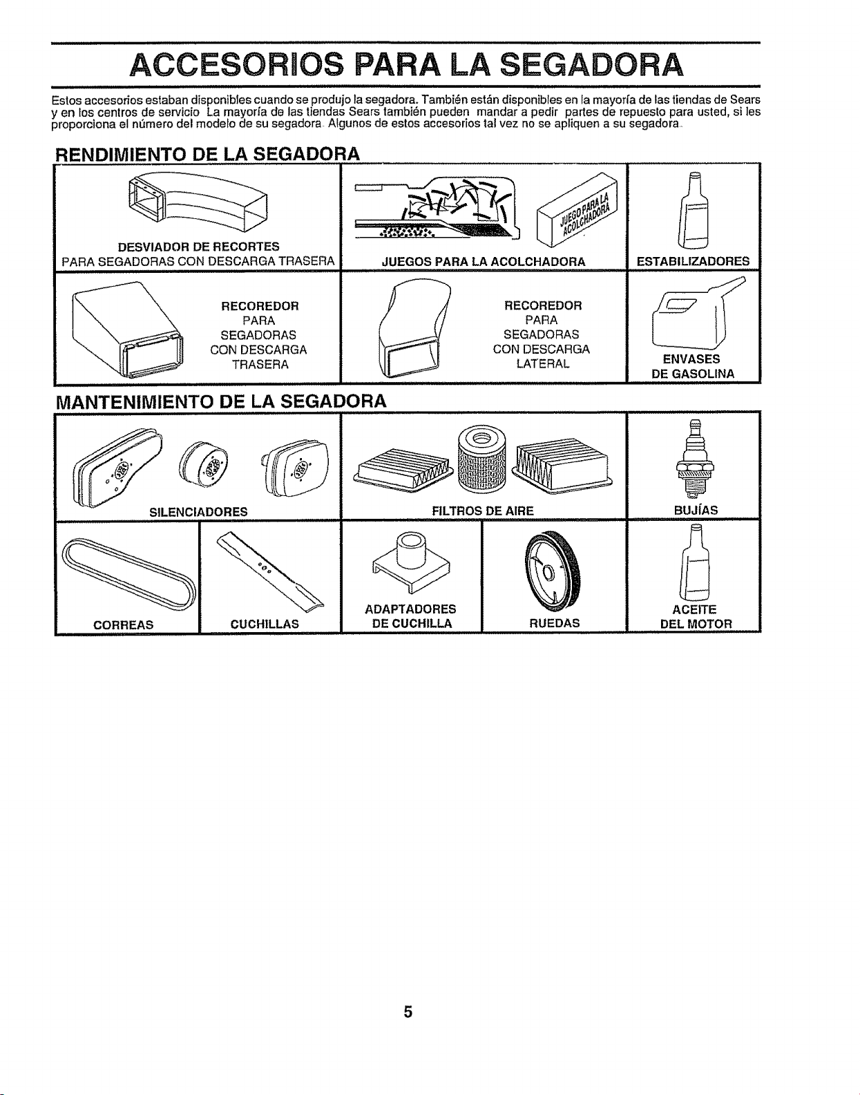
ACCESORIOS PARA LA EGA RA
i i i i i iiii, iii i
Estos accesorios ostaban d{sponiblescuando se produjota segadora. Tambi_n est__ndisponibfeson la mayorfa de las tiendas de Sears
yen los centros de serv!c o La mayor_ade las fiendas Sears tambi_n pueden rnandar a pedir partes de repuesto para usted, si les
proporoiona el n_mero eel rnodeto de su sogaaora Aigunos de estos accesodos tal vez no se apliquen a su segadora
RENDIMIENTO DE LA SEGADORA
DESVIADOR DE RECORTES
PARA SEGADORAS CON DESCARGA TRASERA
RECOREDOR
PARA
SEGADORAS
CON DESCARGA
TRASERA
JUEGOS PARA LA ACOLCHADORA
RECOREDOR
PARA
SEGADORAS
CON DESCARGA
LATERAL
MANTENIMIENTO DE LA SEGADORA
SILENCIADORES FILTROS DE AIRE
CORREAS
..........................illll i ,ll,llllllll
CUCHILLAS
ADAPTADORES
DE CUCHILLA RUEDAS
,,,,, ,,,iHll
ESTABILIZADORES
ENVASES
DE GASOLINA
BUJ|AS
ACEITE
DEL MOTOR
5
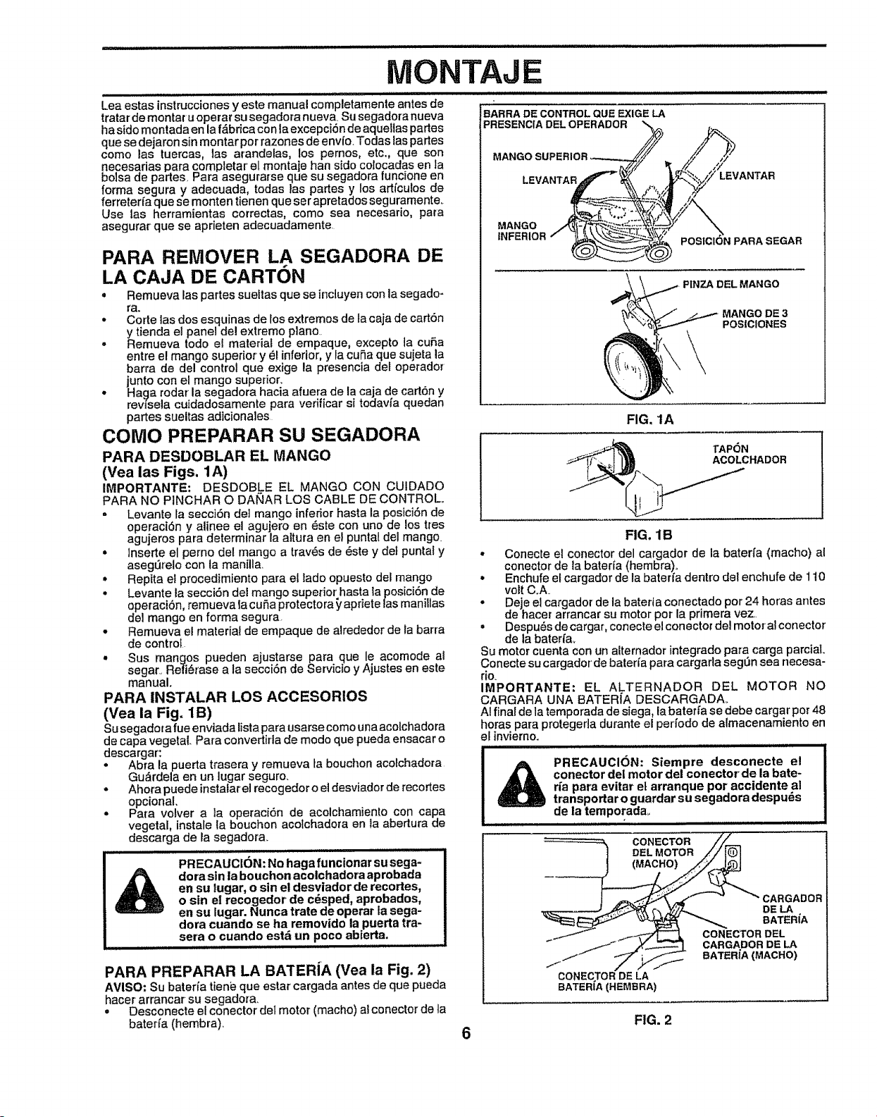
ONTAJE
i illlllll
Lea estas instrucciones y este manual completamente antes de
tratar de montat u operar su segadora nueva Su segadora nueva
haside montada en la f_brica con laexcepci6n de aqueitaspartes
quese dejaron sin montar per razones de envfo.Todas taspartes
come las tuercas, las arandelas, los pernos, etc., que son
necesarias para completar el montaje ban side colocadas en la
bolsa de partes, Para asegurarse que su segadora funcione en
forma segura y adecuada, todas |as partes y los art{culos de
ferreterfa que se monten tienen que ser apretados seguramente_
Use |as herramientas correctas, come sea necesario, para
asegurar que se aprieten adecuadamente
PARA REMOVER LA SEGADORA DE
LA CAJA DE CARTON
. Remueva las partes suet|as que se incluyen con la segado-
ra.
• Corte las dos esquinas de los extremes de la caja de cart6n
y tienda el panel del extreme piano
° Remueva lode el material de empaque, excepto ia cuSa
entre el mango superior y _I inferior, y la cuSa que sujeta la
barra de de! control que extge la presencia del operador
junto con el mango superior.
° Haga rodar la segadora hacia afuera de la caja de cart6n y
rev{sela cuidadosamente para verificar si todavia quedan
partes sueltas adicionales
COMe PREPARAR SU SEGADORA
PARA DESDOBLAR EL MANGO
(Vea ias Figs, 1A)
IMPORTANTE: DESDOBLE EL MANGO CON CUIDADO
PARA NO PINCHAR O DAi_AR LOS CABLE DE CONTROL,.
= Levante _asecci6n dei mango inferior hasta la posici6n de
operaci6n y alinee el agujero en _ste con uno de los tres
agujeros para determinar la aitura en el puntal del mango.
= lnserte el perno del mango a |raves de _ste y det pun|a! y
aseg_reio con ta manilla.
• Repita el procedimiento para ef lade opuesto del mango
• Levante la secci6n del mango superior hasta la posici6n de
operaci6n, remueva Ia cuSa protectora _'apriete las manillas
del mango en forma segura
• Remueva el material de empaque de alrededor de ia barra
de control
. Sus mangos pueden ajustarse para que le acomode al
segar, Re|i6rase a la secci6n de Servicio y Ajustes en este
manual.
PARA INSTALAR LOS ACCESORIOS
(Vea la Fig. 1B)
Su segado{a rue enviada lista para usarse come una acolchadora
de capa vegetal Para convertirla de mode que pueda ensacar o
descargar:
= Abra la puerta trasera y remueva ta bouchon aco_chadora
Gu_rdela en un tugar seguro.
• Ahora puede instalarel recogedor o el desviador de recortes
opcional.
• Para volver a la operaci6n de acotchamiento con capa
vegetal, instale la bouchon acotchadora en Ia abertura de
descarga de la segadora,.
PRECAUCI6N: No haga funcionar su sega-
dora sin la bouchon acolchadora aprobada
en su |ugar, o sin el desviador de recortes,
o sin el recogedor de cdsped, aprobados,
en su lugar. Nunca trate de operar la sega-
dora cuando se ha removido la puerta tra-
sera o cuando estd un poco abierta.
PARA PREPARAR LA BATERIA (Yea la Fig. 2)
AVISO: Su baterfa tienb que estar cargada antes de que pueda
hacer arrancar su segadora.
• Desconecte el conector del motor (macho) al conector de ta
baterfa (hembra),
BARRA DE CONTROL QUE EXIGE LA
PRESENCIA DEL OPERADOR
MANGO SUPERIOR
LEVANTAR
LEVANTAR
MANGO
INFERIOR
POSICION PARASEGAR
PINZA DEL MANGO
MANGO DE 3
POSICIONES
FIG. 1A
FIG. 1B
* Conecte el conector del cargador de la baterfa (macho) al
conector de {a bateria (hembra),
. Enchufe el cargador de la bater_'aden|re del enchufe de 110
voltC_A=
° Deje el cargador de la bateria conectado per 24 horas antes
de hacer arrancar su motor per la primera vez
° Despu_s de cargar, conecteel conector del motor' al conector
de la baterfa_
Su motor cuenta con un altemador integrado para carga parciaL
Conecte su cargador de bateria para cargarla segL_nsea necesa-
rio.
IMPORTANTE: EL ALTERNADOR DEL MOTOR NO
CARGARA UNA BATER{A DESCARGADA_
AI final de la temporada de siega, la bater_a se debe cargar per 48
horas para protegerla durante el perlodo de almacenamiento en
el invierno.
PRECAUCION: Siempre desconecte e!
conector del motor del conector de la bate-
rfa para evitar et arranque per accidente al
transportar o guardar su segadora despu_s
de la temporada,.
CONECTOR
DELMOTOR
(MACHO)
/
CONECTOR DELA
BATER{A(HEMBRA)
CARGADOR
DE LA
BATER_
CONECTORDEL
CARGADOR DE LA
BATERiA{MACHO)
FIG. 2
6
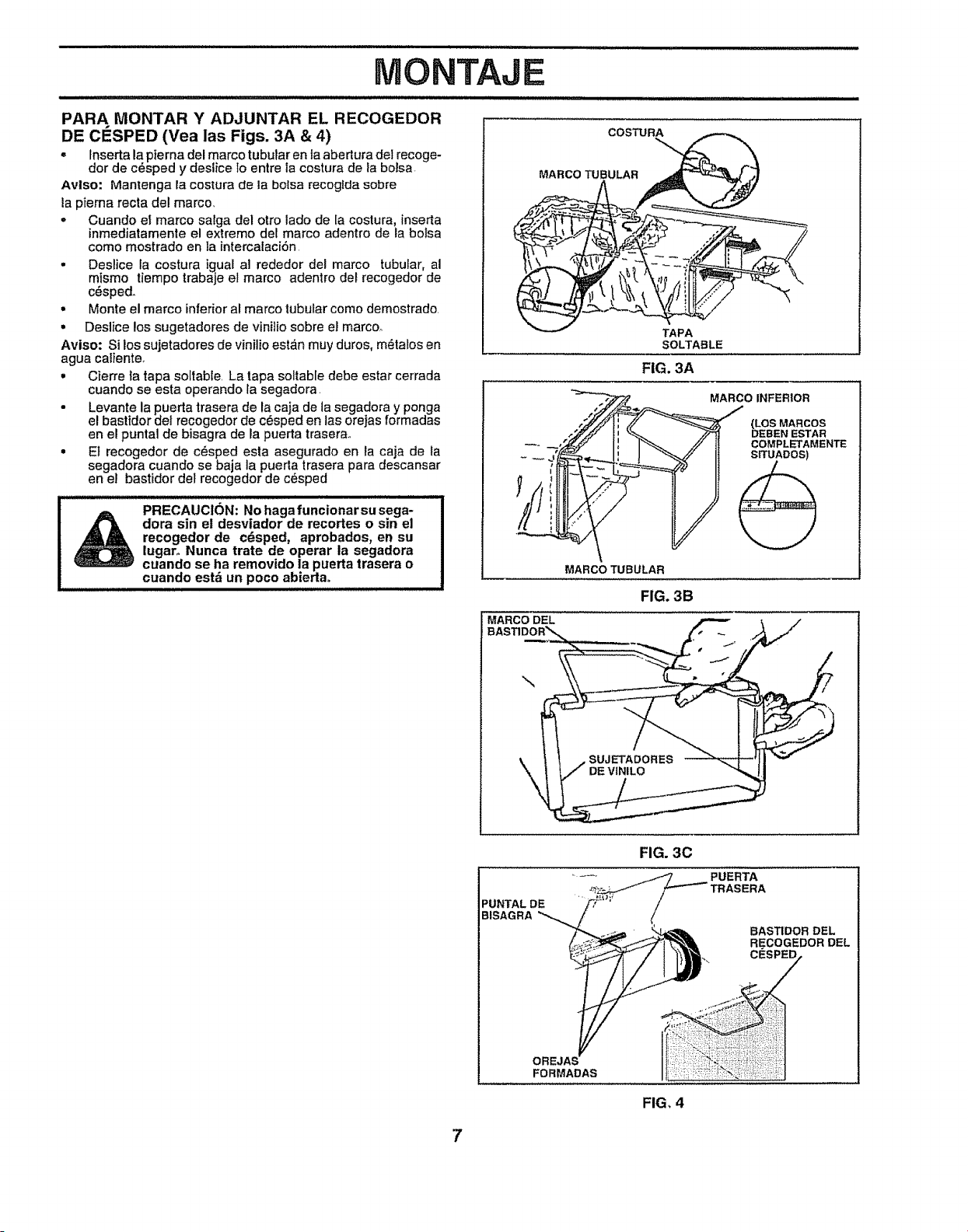
i1,1,iiiii i,,,,, ,
MONTAJE
PARA MONTAR Y ADJUNTAR EL RECOGEDOR
DE CESPED (Yea las Figs. 3A & 4)
,, Inserta la pierna del marco tubutar en la abertura del recoge-
dor de c6sped y deslice Io entre 1acostura de la bolsa
Arise: Mantenga la costura de la bolsa recoglda sobre
la piema recta del marco_
- Cuando el marco satga del otto tado de la costura, {nserta
inmediatamente el extreme del marco adentro de la bolsa
come mostrado en la intercalaci6n
• Deslice {a costura igual a] rededor del marco tubular, al
mismo tiempo trabaje el marco adentro det recogedor de
c_sped.
• Monte el marco inferior al marco tubular come demostrado.
• Deslice los sugetadores de vinilio sobre el marco°
Aviso: Si los sujetadores de vinilio est6n muy duros, m_talos en
agua caliente,
• Cierre la tapa soltab{e. La tapa soltable debe estar cerrada
cuando se esta operando la segadora.
• Levante la puerta trasera de la caja de la segadora y ponga
el bastidor del recogedor de c_sped en las orejas formadas
en el puntal de bisagra de la puerta traserao
• Et recogedor de c_sped esta asegurado en ia caja de la
segadora cuando se baja la puerta trasera para descansar
en el bastidor det recogedor de c_sped
PRECAUCION" No haga funcionar su sega-
A dora sin el desviador de recortes o sin el
recogedor de c_.sped, aprobados, en su
tugaro Nunca trate de operar la segadora
cuando se ha removido la puerta trasera o
cuando est_ un poco abierta°
COSTURA
MARCO TUBULAR
TAPA
SOLTABLE
FIG. 3A
_ MARCO INFERIOR
,,._ {i _ _2_ DEBEN ESTAR
---,,5_ II _ _" li COMPLETAMENTE
MARCO TUBULAR
FIG. 3B
MARCO DEL
\
PUNTALDE
BISAGRA
FIG. 30
OREJAS
FORMADAS
FIG, 4
7
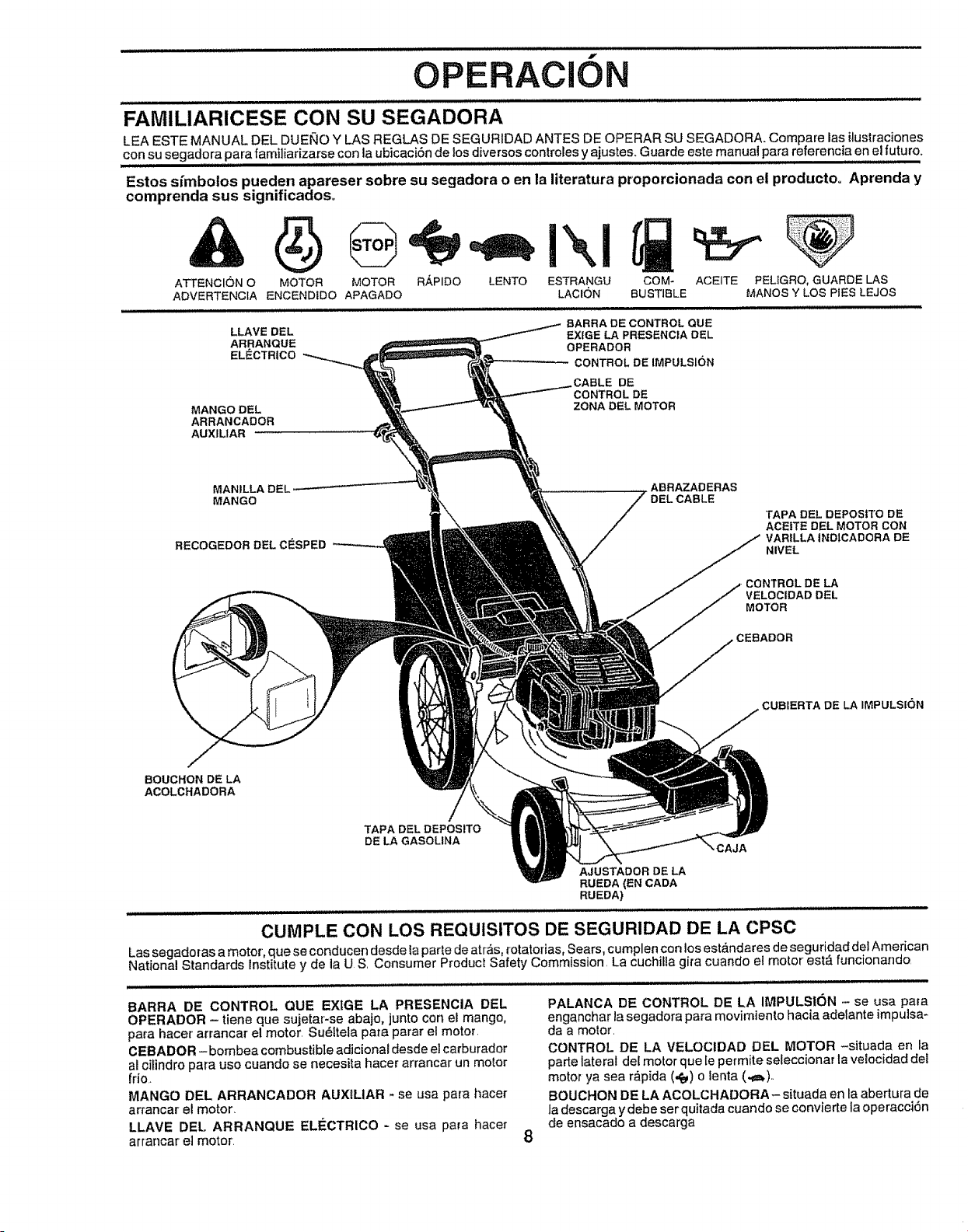
....... ill ii ii
f
OPERACiON
UI,II
FAMILIARICESE CON SU SEGADORA
LEA ESTE MANUAL DEL DUE[_'.IOY LAS REGLAS DE SEGURIDAD ANTES DE OPERAR SU SEGADORA. Compare Ias ilustraciones
con su segadora para familiarizarse con la ubicaci6n de los diversos controles y ajustes. Guarde este manual para referencia en el futuro_
Estos sfmboios pueden apareser sobre su segadora o en la literatura proporcionada con el producto° Aprenda y
comprenda sus significados_
ATTENCION O LENTO COM-
ADVERTENCfA BUSTIBLE
MOTOR MOTOR R,_PIDO
ENCENDIDO APAGADO
!\1
ESTRANGU
LACK3N
ACEITE PELIGRO, GUARDE LAS
MANOS Y LOS PiES LEJOS
LLAVE DEL
ARRANQUE
ELECTR|CO
BARRA DECONTROLQUE
EX[GELAPRESENCIA DEL
OPERADOR
CONTROLDEIMPULSION
MANGO DEL
ARRANCADOR
AUXIL1AR
CABLE DE
CONTROL DE
ZONA DEL MOTOR
MANILLA DEL
MANGO
RECOGEDOR DELCESPED
ABRAZADERAS
TAPA DEL DEPOStTO DE
ACEITE DEL MOTOR CON
VARILLAINDtCADORA DE
NIVEL
3E LA
VELOC[DAD DEL
MOTOR
,CEBADOR
CUBIERTA DE LA IMPULSION
/
BOUCHON DE LA
ACOLCHADORA
TAPA DELDEPOSITO
DE LA GASOLINA
AJUSTADOR DE LA
RUEDA(EN CADA
RUEDA)
,CAJA
CUMPLE CON LOS REQUISITOS DE SEGURIDAD DE LA CPSC
Las segadoras a motor, que se conducen desde laparte de arras rotatofias Sears, cumplen con los estandares de seguridad del American
National Standards Institute y de la U S, Consumer Produc! Safety Commission, La cuchil a gira cuando e motor estA funcionando,
BARRA DE CONTROL QUE EXIGE LA PRESENCIA DEL
OPERADOR - tiene que sujetar-se abajo, junto con el mango,
para hacer arrancar el motor, Su_itela para parar el motor.
CEBADOR -bombea combustibIe adiciona[ desde el carburador
al ci[indro para uso cuando se necesita hacer arrancar un motor
[rio
MANGO DEL ARRANCADOR AUXlLIAR - se usa para hacer
arrancar el motor,
LLAVE DEL ARRANQUE ELECTRICO - se usa para hacer
arrancar el motor.
8
PALANCA DE CONTROL DE LA IMPULSION - se usa para
enganchar la segadora para movimiento hacia adelante impulsa_
da a mo!or,
CONTROL DE LA VELOCIDAD DEL MOTOR -situada en la
parte lateral de[ motor que repermite seleccionar la ve[ocidad del
motor ya sea r_pida (,t_) o lenta (._a_),.
BOUCHON DE LA ACOLCHADORA- situada en la abertura de
ta descarga y debe ser quitada cuando se convierte la operacci6n
de ensacado a descarga
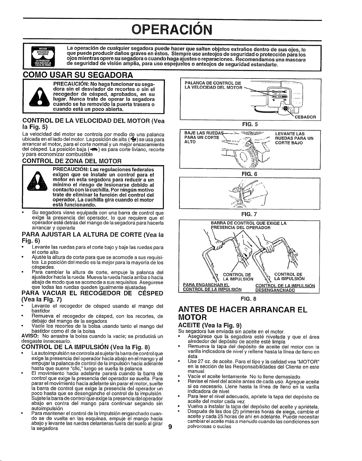
f
OPERACION
La operacidn de cualquier segadora puede hacer que salten objetos extrafios dentro de sus ojos, Io
que puede producir daSos graves en dstos. Siempre use anteojos de seguridad o protecci6n para los
ojos mientras opere su segadora o cuando haga ajustes o reparaciones. Recomendamos una mascara
de seguridad de visi6n amplia, para uso espejuelos o anteojos de seguridad estandarte.
COMO USAR SU SEGADORA
PRECAUCI6N: No haga funcionar su sega-
dora sin el desviador de recortes o sin e!
recogedor de c_sped, aprobados, en su
iugaro Nunca trate de operar la segadora
cuando se ha removido la puerta trasera o
cuando estz_un poco abierta.
CONTROL DE LA VELOCIDAD DEL MOTOR (Vea
ta Fig. 5)
La velocidad del motor se controla por medio d.euna palanca
ubicada en el tado del motor.. La posiciSn de atta ("_,) se usa para
arrancar el motor, para el corte normal y un mejor ensacamiento
del c6sped. La posici6n baja (,_=_) es para corte tiviano, recorte
y para economizar combustible
CONTROL DE ZONA DEL MOTOR
PRECAUCI6N; Las regulaciones federates
exigen que se instale un contro! para el
motor en esta segadora para reducir a un
mfnimo el riesgo de tesionarse debido at
contacto con la cuchilIa. Pot ning_n motivo
trate de eliminar la funci6n del control det
operadoro La cuchtlla gira cuando el motor
est_ funcionando.
Su segadora viene equipada con una barra de control que
exige la presencia del operador, 1o que requiere que el
operador est6 detrAs del mango de la segadora para hacerla
arrancar y operarta
PARA AJUSTAR LA ALTURA DE CORTE (Yea la
Fig. 6)
. Levante las ruedas para el corte bajo y baje las ruedas para
el code alto,
• Ajuste la altura de corte para que se acomode a sus requisi-
tos. La posici6n del medio es la mejor para la mayoria de los
c6spedes..
• Para cambiar ta altura de corte, empuje la palanca del
ajustador hacia la rueda Mueva fa rueda hacia arriba o hacla
abajo de modo que se acomode a sus requisitos Aseg0rese
que todas las ruedas queden igualmente ajustadas
PARA VACIAR EL RECOGEDOR DE CESPED
(Yea la Fig. 7)
• Levante e! recogedor de c_sped usando el mango del
bastidor,
• Remueva el recogedor de c_sped, con los recortes, de
debajo del mango de la segadora
• Vacfe los recortes de la bolsa usando tanto el mango del
bastidor como _l de la bolsa,
AVISO: No arrastre la bolsa cuando la vacfe; se producir_ un
desgaste innecesario.
CONTROL DE LA IMPULSl6N (Vea ta Fig. 8)
• La autoimpulsi6n se controia al sujeta rta barra de control que
exlge la presencia del operador hacia abajo en el mango y al
empujar la palanca de control de la impulsiSnhacla adelante
hasta que suene "clic," fuego se suelta la patanca
• El movimiento hacia adelante parar& cuando la barra de
control que exige la presencia del operador se sueila. Para
parar el movimiento hacia adelante sin parar el motor, suelte
la barra de control que exige la presencia del operador un
poco hasta que se desenganche el control de la impulsi6n.
Sujete la barra de control que exige la presencia del operador
abajo en contra del mango para continuar segando sin
autoimpulsiSn
• Para mantener el control de la impulsiSn enganchado cuan*
do se de vuelta en fas esquinas, empuje el mango hacia
abajo y levante las ruedas delanteras fuera del suelo at girar
la segadora
9
PALANCA DE CONTROL DE "_"+--__............
LA VELOCIDAD DEL MOTOR _ _I1
___ _ _"_"
"CEBADOR
FIG. 5
BAJE LAS RUEDA_,i---_- ___
PARA UN CORTE _ -.:.-_._ ._
"%,. /_b'
FIG. 6
LEVANTELAS
RUEDAS PARA UN
CORTEBAJO
FIG. 7
\
P ARA ENGANCNAR EL
CONTROL DE LA IMPULSfON
BARRA DE CONTROL QUE EXIGE LA
_ES_ERADOR
_, LA IMPULSI6N "_, LA IMPULSION
CONTROLOELAiM_ULSi6N
pESENGANCHADO
FIG. 8
ANTES DE HACER ARRANCAR EL
MOTOR
ACEITE (Vea la Fig. 9)
so segadora rue enviada sin ace!re en el motor.
° Asegerese que la segadora est_ nivelada y que el a'rea
alrededor del depSsito de aceite est6 limpia
,, Remueva la lapa de! depSsito de aceile de] molor con ta
varilla indicadora de nivel y rellene hasla la lfnea de Ileno en
6sta.
• Use 27 oz. de ace!re, Para ei tipo y ]acaidad vea "MOTOR"
en la secci6n de las Responsabilidades del Cliente en este
manual
,, Vacie el aceite lentamente No 1oflene demasiado,
• Revise el nivel del aceite antes de cada uso, Agregue aceile
si es necesario. Llene hasta la Ifnea de lleno en la varilla
indicadora de nivel
° Para leer e! nivel adecuado, apriete la tapa del dep6sto de
aceite del motor cada vez
• Vuelva a instalar la tapa del depSsito del aceite y aprieiela,
• Despues de las dos (2) primeras horas de siega, cambie el
aceite y cada 25 horas de ahf en adelante. Puede necesitar
cambiar e! aceite mas a menudo cuando las condiciones son
polvorosas o sucias
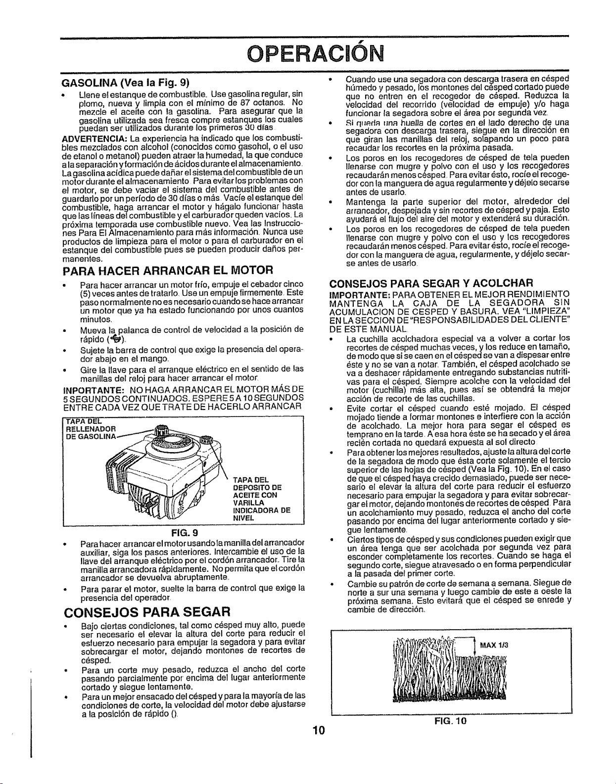
f
OPEBACION
................ill ....... ::: IJIH
GASOLtNA (Vea la Fig. 9)
- Llene e! estanque de combustible. Use gasolina regular, sin
plomo, nueva _ limpia con el minimo de 87 octanes. No
mezcte el ace=te con la gasolina. Para asegurar que la
gaso.lina utilizada sea fresca, compre estanques los cuales
pueaan ser uli_izaaos aurante lOSprimeros 30 dfas
ADVERTENCIA: La experiencia ha indicado que los combusti-
bles mezclados con alcohol (eonocidos como gasohol, o e! uso
de etano! o metanol) pueden atraer la humedad, la que conduce
a la separaci6n yformaciSn de _.cidosdurante elalmacenamiento.
La gasolina acidica puede daSar et sistema del combustible de un
motor durante el atmacenamiento Para evitar los problemas con
el motor, se debe vaciar el sistema del combustible antes de
guardaflo por un perfodo de 30 dfas o m&s Vacfe el estanque del
combustible, haga arrancar el motor y h_gato funcionar hasta
que fas lineas dei combustible y el carburador queden vacios. La
pr6xima temporada use combustible nuevo. Vea tas Instruccio-
nes Para El Aimacenamiento para m&s informaciSn Nunca use
productos de limpieza para el motor o para el carburador en et
estanque del combustible pues se pueden producir daSos per-
manenteso
PARA HACER ARRANCAR EL MOTOR
• Para hacer arrancar un motor fHo, empuje el cebador cinco
(5) veces antes de tratarlo. Use un empuje firmemente. Este
paso normalmente no es necesario cuando se hace arrancar
un motor que ya ha estado funcionando por unos cuantos
minutos.
• Mueva la palanca de control de velocidad a la posici6n de
r&pido (_).
• Sujete la barra de control que exige la presencia del opera-
dot abajo en el mango_
• Gire la Uave para el arranque el_ctrico en el sentido de las
mani!las del reloj para hacer arrancar el moto_
INPORTANTE: NO HAGAARRANCAR EL MOTOR M/_S DE
5 SEGUNDOS CONTINUADOS. ESPERE 5 A !0 SEGUNDOS
ENTRE CADA VEZ QUE TRATE DE HACERLO ARRANCAR
TAPA DEL
RELLENADOR
DE
TAPA DEL
DEPOSITO DE
ACE|TE CON
VAR|LLA
IND1CADORA DE
NIVEL
FIG. 9
° Para hacer arrancar el motor usandola manilla delarrancador
auxiliar, siga los pasos anteriores. Intercambie el uso de la
!lave del arranque el6ctrioo por el cord6n arrancador.. Tire la
manilla arrancadora r&pidamente. No permita que el cordSn
arrancador se devuelva abruptamente.
° Para parar et motor, suelte ta barra de control que extge ta
presencia del operador
CONSEJOS PARA SEGAR
• Bajo ciertas condictones, tal come c_sped muy alto, puede
ser necesario el elevar ]a altura del corte para reducir el
esluerzo necesario para empujar ta segadora y para evitar
sobrecargar el motor, dejando montones de recortes de
c_sped..
,, Para un corte muy pesado, reduzca el ancho del corte
pasando parcialmente por encima de1 lugal anteriormente
cortado y s{egue lentamente.
• Para un mejor ensacado del c_sped y para la mayor(a de las
condiciones de code, la velocidad del motor debe ajustarse
a la posicl6n de r_pido 0.
t)
10
Cuando use una segadora con doscarga trasera on c_sped
hSmedo y pesado, los montones del c_sped cortado puede
que no entren en el recogodor de c_sped. Reduzca ta
velocidad del recorrido (velocidad de empuje) yto haga
funcionar la segadora sobre et ,_rea po[ segunda vez.
° ,._iqNP.datma huelta de codes en el lado dorecho de una
sogadora con descarga trasera, siegue on la direcciSn en
que giran ]as manillas def reloj, sotapando un poco para
roeaudar los recortes en la prSxima pasadao
° Los poros en los recogedores de c6sped de tela pueden
ltenarse con mugre y polvo con el uso y los recogedores
recaudar_,n menos c_sped Para evilar _sto, roc_'eel recoge-
der con la manguera de agua regularmente y d_jefo secarso
antes de usarlo.
° Mantenga la parte superior del motor, alrededor det
arrancador, despejada y sin recortes de cesped y paja. Esto
ayudar& el flujo del aire del motor y extender_ su duraciSn.
• Los poros en los recogedores de c6sped de tela puoden
Ilenarse con mugre y polvo con el uso y los recogedores
recaudar&n menos cesped. Para evitar _sto, rocheel recoge-
dot con la manguera de agua, regularmente, y d_jelo secar-
se antes de usado.
CONSEJOS PARA SEGAR Y ACOLCHAR
IMPORTANTE: PARA OBTENER EL MEJOR REHDIMIENi"O
MANTENGA LA CAJA DE LA SEGADORA SIN
ACUMULACION DE CESPED Y BASURA. VEA "LIMPIEZA"
EN LA SECCtON DE"RESPONSAB1LIDADES DEL CLIENTE"
DE ESTE MANUAL
° La cuchitla acolchadora especial va a volver a cortar los
recortes de c6sped muchas veces,y los reduce en tamaSo,
de modo que si se caen en el c_spedse van a dispesar entre
_ste y no se van a notar. Tambi_n, el c_sped acolchado se
va a deshacer r_pidamente entregando substancias nutriti-
vas para el c_sped, Siempre acolche con la velocidad del
motor (cuchilla) m_s alta, pues asf se obtendr_ la mejor
acciSn de recorte de las cuchtllas..
• Evite cortar el c_sped cuando est_ mojado. Et c_sped
mojado tiende a formar montones e interfiere con la acci6n
de acolchado. La mejor hora para segar el c_sped es
temprano en la tarde. A osa hora _ste se ha secado y el _rea
reci_n cortada no quedar_ expuesta al so! directo
• Para obtener los mejores resultados, ajuste ta altura del corte
de la segadora de modo quo 6sta corte solamente el tercio
superior de las hojas de c_sped (Vea la Fig. 10). En el caso
de que el c_sped haya crocido demasiado, puede ser nece-
sario e! elevar ta altura del corte para reducir et esfuorzo
necosario para empujar la segadora y para evitar sobrecar-
gar el motor, dojando montones de recortes de c_sped Para
un acolchamiento muy pesado, reduzca el ancho del corte
pasando pot encima del lugar antertormente codado y sie-
gue lentamente.
• Ciertos tipos de c6sped y sus condiciones pueden exigir que
un _rea tenga que set acolchada por segunda vez para
esconder completamente los recortes.. Cuando se haga el
segundo code, siegue atravesado o en forma perpendicular
a la pasada del primer code..
• Cambie su patron de code de semana a semana. Siegue de
norte a sur una semana y luego cambie de este a oeste la
pr6xima semana, Esto evitara queet c_asped se enrede y
cambie de direcci6n..
MAX 1t3
FIG. 10
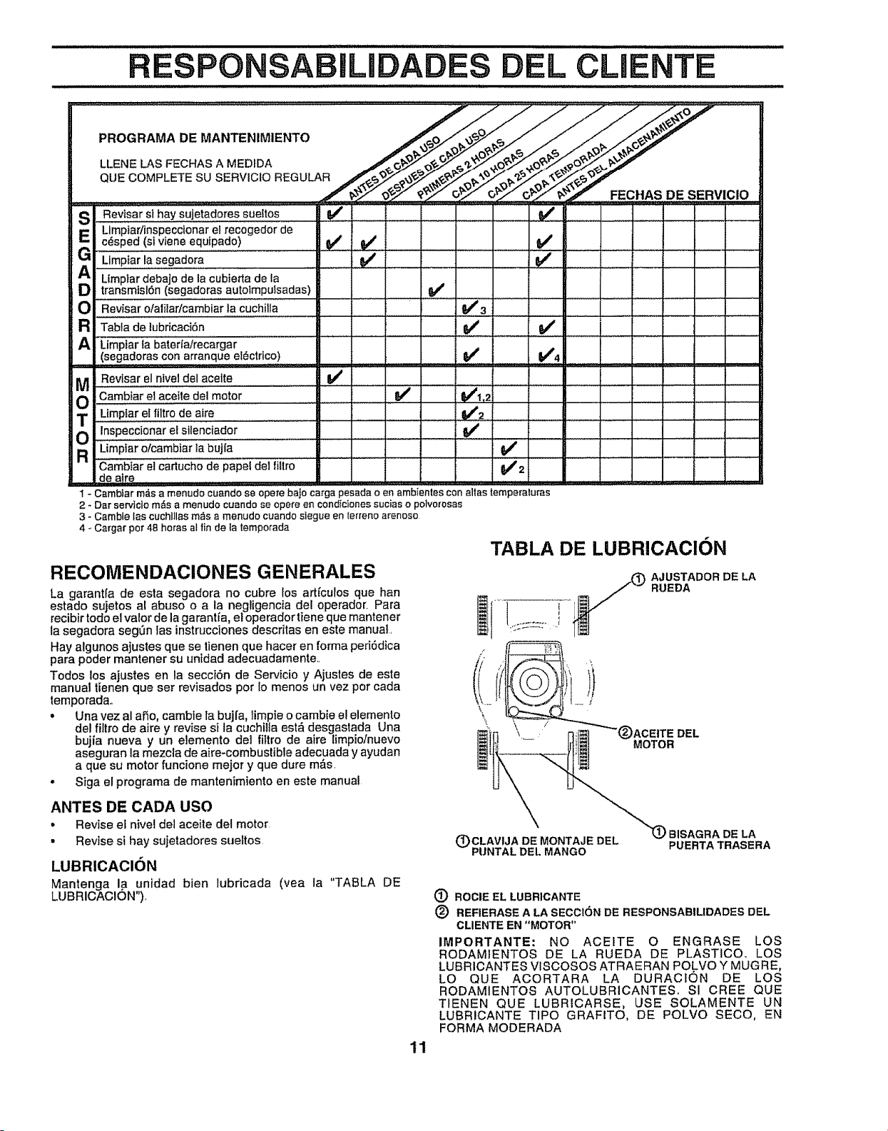
RESP SABILIDAD DEL CLIENTE
S l Revisar sl hay sujetadores sueltos
Limpiar/inspeccionare_recogedor de
(E_ c_sped (sivlene equipado)
LimpEarlasega_ora
A umpiar_obaj0deiaCub_e_ta,_e_a
transmislSn (segadoras autolmpu3sadas)
O Revisar otaliladcambiarla cuchilla
a l Tabla de lubricaciSn
A Limpiar la baterfairecargar
(segadoras conarranqueel_ctrico)
,v' ......
v'
V' V'
I Revtsar el nivel del acette V'
ouCam i reiace"ede,'mo'ior.......... I I V'f ...... I,, .....
Ltmplar el ftltro de aire _ t V'2
o!T=inspecci0nar el stlenciador
............
_
_
J
_
,
_
R Limpiaroicambiariabujra .... I I I I
Cambiar el cartucho de Papel dei fiitro J 2
de atre ..................... --
1 - Cambtarm_sa menudocuandoseoperebajocarga pesadaoenamb/entescon altastemperaluras
2 - Darservlciorn_sa menudocuandoseopereen condicionessuciaso polvo[osas
3 * Carnble las cuchl]lasm_s a menudo cuandostegt_een lerreno arenoso
4 _ Cargar pot 48 horas al fin de la ternporada
RECOMENDACIONES GENERALES
La garantla de esta segadora no cubre los artfculos que han
estado sujetos al abuso o a la negligencia del operador. Para
recibirtodo el valor de la garantia, el operador tiene que mantener
la segadora segSn las instrucciones descritas en este manual.
Hay algunos ajustes que se lienen que hacer en forma peri6dica
para poder mantener su unidad adecuadamente..
Todos los ajustes en la secck_n de Servicio y Ajustes de este
manual tienen que ser revisados por lo menos un vez pot cada
temporadao
• Una vez al afio, cambie la buj[a, limpie o cambie el elemento
del filtro de aire y revise si ta cuchilta est_ desgastada Una
bujia nueva y un elemento del fillro de aire {impio/nuevo
aseguran la mezcla de aire_combustible adecuada y ayudan
a que su motor funcione mejor y que dure mAs.
• Siga el programa de mantenimiento en este manual
ANTES DE CADA USO
• Revise el n_veldel aceile del motor
• Revise si hay sujetadores sueltos
LUBRICACION
Mantenga la unidad bien lubricada
LUBRICACION")_
(yea la "TABLA DE
TABLA DE LUBRICAClON
I)
AJUSTADOR DE LA
RUEDA
DEL
MOTOR
(_ CLAVIJA DE MONTAJE DEL
PUNTAL DEL MANGO
_J BISAGRA DE LA
PUERTA TRASERA
(_) ROCiE EL LUBR1CANTE
(_) REFIERASE A LA SECCI6N DE RESPONSABILIDADES DEL
CLIENTE EN "MOTOR"
IMPORTANTE: NO ACEITE O ENGRASE LOS
RODAMIENTOS DE LA RUEDA DE PLASTICO_ LOS
LUBRICANTES VISCOSOS ATRAERAN POLVO Y MUGRE,
LO QUE ACORTARA LA DURACt(SN DE LOS
RODAMIENTOS AUTOLUBRICANTES. SI CREE QUE
TIENEN QUE LUBRICARSE, USE SOLAMENTE UN
LUBRICANTE TIPO GRAFITO, DE POLVO SECO, EN
FORMA MODERADA
11
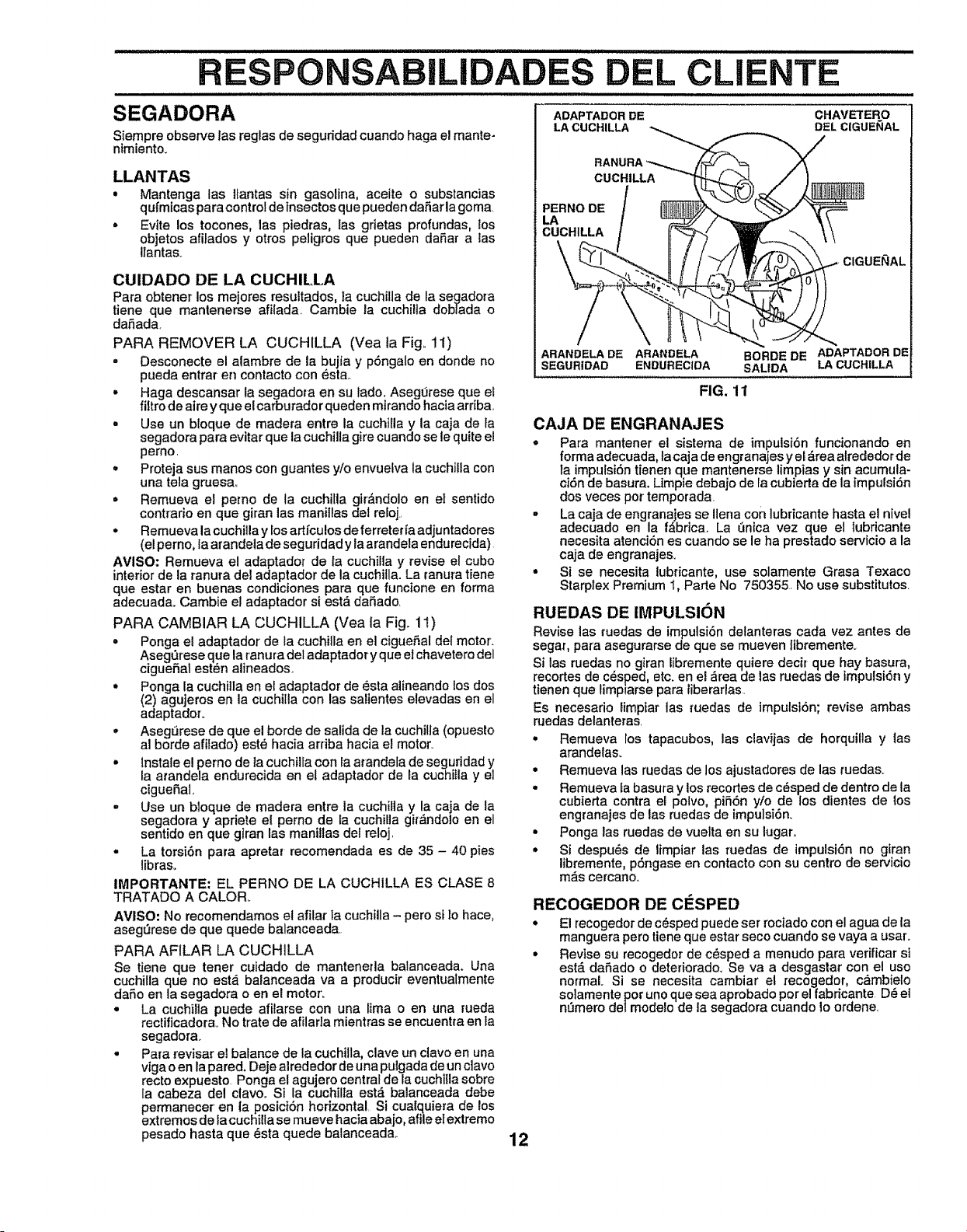
I/IIJUl II I IIlllll I I I I II I k
BILIDA DEL CLIENTE
SEGADORA
Siempre observe las regias de seguridad cuando haga el mante-
nimiento.
LLANTAS
• Mantenga las llantas sin gasolina, aceite o substancias
qufmicas para control de insectos que pueden daSar la goma
• Evite los tocones, las piedras, las grietas profundas, los
objetos afilados y otros pefigros que pueden daSar a tas
Itanta&
CUIDADO DE LA CUCHILLA
Para obtener los mejores resultados, la cuchilla de ta segadora
tiene que mantenerse afiiada Cambie la cuchiUa dobtada o
daSada
PARA REMOVER LA CUCHILLA (Vea la Fig_ 11)
° Desconecte el alambre de la bujfa y p6ngalo en donde no
pueda entrar en contacto con est&
° Haga descansar la segadora en su lado. Asegt]rese que ei
_tro de aire y que el carburador queden mirando hacia ardba.
• Use un bloque de madera entre la cuchilla y la caja de la
segadora para evitar que la cuchilla gire cuando se le quite el
pemo.
• Proteja sus manos con guantes y!o envuefva la cuchilla con
una tela gruesa,.
= Remueva el pemo de la cuchilla girAndolo en eI sent|do
contrarie en que giran las manillas det re_oj..
° Remueva la cuchilla y los artfculos de ferreter[a adjuntadores
(el perno, la arandela de seguridad y la arandela endurecJda)
AVISO: Remueva el adaptador de la cuchilla y revise el cubo
interior de la ranura del adaptador de la cuchitla. La ranura tiene
que estar en buenas condiciones para que funcione en forma
adecuada, Cambie el adaptador si est,_daSado.
PARA CAMBIAR LA CUCHILLA (Vea la Fig., 11)
° Ponga el adaptador de la cuchilla en el cigueSal del motor.
AsegQrese que la ranura del adaptador y que el chavetero del
cigueSai est_n alineados,
° Ponga la cuchilla en el adaptador de esta alineando los dos
(2) agujeros en la cuchiIla con las salientes elevadas en el
adaptadoro
,, Aseg_rese de que el borde de salida de la cuchilfa (opuesto
al borde afitado) est_ hacia arriba hacia el motor.
,, lnstale e! perno de la cuchilla con la arandela de seguridad y
la atandela endurecida en el adaptador de la cuchiIla y el
cigueSal,
= Use un bloque de madera entre la cuchilla y la caja de la
segadora y apriete el perno de la cuohilla git_ndolo en el
sentido en que giran las manUlas del reloj.
• La torsi6n para apretar recomendada es de 35 - 40 pies
libraso
IMPORTANTE: EL PERNO DE LA CUCHILLA ES CLASE 8
TRATADO A CALOR.
AVISO: No recomendamos el afilar la cuchilla - pero si 3ohace,
asegt3rese de que quede balanceada
PARA AFILAR LA CUCHiLLA
Se tiene que tener cuidado de manteneda balanceada. Una
cuchilla que no estA balanceada va a producir eventuatmente
dafio en la segadora o en el motor_
• La cuchilla puede afilarse con una lima o en una rueda
rectiflcadorao No trate de afilarla mientras se encuentra en ta
segador&
° Para revisar el balance de la cuchilla, clave un clavo en una
viga o en lapared. Deje alrededor de una pulgada de un clavo
recto expuesto Ponga e! agujero central de la cuchilla sobre
la cabeza del clave. Si la cuchilla est_ balanceada debe
permanecer en la posici6n horizontal Si cualquiera de los
extremes de la cuchilla se mueve hacia abajo, affie el extremo
pesado hasta que esta quede balancead&
ADAPTADOR DE CHAVETERO
LA CUCHILLA DEL ClGUEI(IAL
CUCHILLA
PERNO DE
LA
CUCHILLA
ARANDELADE ARANDELA
SEGUR|DAD ENDURECIDA
FIG. 11
ClGUENAL
BORDE DE ADAPTADOR DE
SALIDA LACUCHILLA
RECOGEDOR DE ClaSPED
° El recogedor de c_sped puede ser rociado con el agua de la
manguera pero tiene que estar seco cuando se vaya a usar.
• Revise su recogedor de cdsped a menudo para verificar si
estd.da5ado o deteriorado. Se va a desgastar con el uso
normal Si se necesita cambiar el recogedor, c_mbielo
solamente por uno que sea aprobado per el fabricante D_ el
n!3mero delmodelo de la segadora cuando 1oordene.
12
RUEDAS DE IMPULSION
Revise las _uedas de impulsi6n delanteras cada vez antes de
segaq para asegurarse de que se mueven ltbremente_
Si las ruedas no giran Eibremente quiere decir que hay basura,
recortes de c_sped, etc. en el _rea de tas ruedas de impulsi6n y
tienen que fimpiarse para liberarlas.
Es necesario limpiar las ruedas de impulst6n; revise ambas
ruedas delanteras.
° Remueva ros tapacubos, las clavijas de horquiIla y las
arandela&
• Remueva las ruedas de los ajustadores de las rueda&
• Remueva fa basura y los recortes de c6sped de dentro de ta
cubierta contra el polvo, pi56n yio de los dientes de los
engranajes de las ruedas de impulsi6n.
° Ponga las ruedas de vuelta en su lugar..
• Si despu_s de fimpiar las /uedas de impulsi6n no giran
libremente, p6ngase en contacto con su centro de servicio
mas cercano.
CAJA DE ENGRANAJES
• Para mantener el sistema de impulsl6n funcionando en
forma adecuada, la caja de engranajes y e_&rea atrededor de
_aimpulst6n tienen que mantenerse limpias y sin acumula-
ci6n de basura. Umpie debajo de la cubierta de la impufsi6n
dos veces por temporada.
• La caja de engranajes se Ilena con lubricante hasta el nivel
adecuado en la f&brica. La P3nicavez que el lubricante
necesita atenci6n es cuando se le ha prestado servicio a la
caja de engranaje&
° Si se necesita lubricante, use solamente Grasa Texaco
Starplex Premium 1, Parte No 750355. No use substitutos
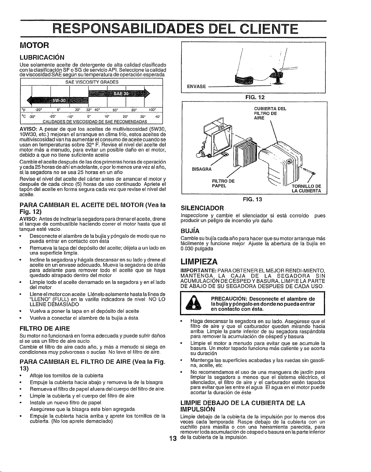
ESPONSABILIDADE
CLIENTE
MOTOR
LUBRICAClON
Use solamente aceite de detergente de alia calidad clasificado
con la clasificaciSn SF o SG de servicio API. Seleccione la calidad
de viscosidad SAE seg,_n su temperatura de operaci6n esperada
SAE VISCOSITY GRADES
4 IIIllmm _E_li ztWm_l
='F -20" 0" 30 = 32 ° 40' 60 • 80 ° _0O°
°c -3'0o -_:Do _1oo 6'_ too 20" _'oo ,,o"
CALIDADES DE V$SCOStDAD DE SAE RECOMENDADAS
AVlSO: A pesar de que los aceites de multiviscosidad (5W30,
!0W30, etc..) mejoran el arranque en clima frio, estos aceites de
multiviscosidad van ha aumentar el consumo de aceite cuando se
usan en temperaturas sobre 32 ° F..Revise el nivel deI aceite del
motor m,_s a menudo, para evitar un posible daSo en el motor,
debido a que no tiene suficiente aceite.
Cambie el aceite despu6s de las dos primeras horas de operaciSn
y cada 25 horas de ah[ en adelante, o por lo menos una vez al aSo,
s[ ia segadora no se usa 25 horas en un aSo.
Revise eI nivet del aceite dei c&rter antes de arrancar el motor y
despu6s de cada cinco (5) horas de uso continuado Apriete el
tapSn del aceite en forma segura cada vez que revise el nivet del
aceite.
PARA CAMBIAR EL ACEITE DEL MOTOR (Vea la
Fig. 12)
AVISO: Antes de inclinar {asegadora para drenar el aceite, drene
el tanque de combustible haciendo correr el motor hasta que el
tanque est6 vacio
- Desconecte et alambre de la bujia y pSngalo de modo que no
pueda entrar en contacto con 6sta
• Remueva la tapa del dep6sito del aceite; d6je/a a un lado en
una superficie limpia,
- incline la segadora y h&gala descansar en su lado y drene el
aceite en un envase adecuado. Mueva la segadora de arras
para adelante para remover todo el aceite que se haya
quedado atrapado dentro del motor
• Limpie todo el aceite derramado en la segadora yen et fado
del motor
• Llene el motorcon aceite Ll_,nelo solamente hasta la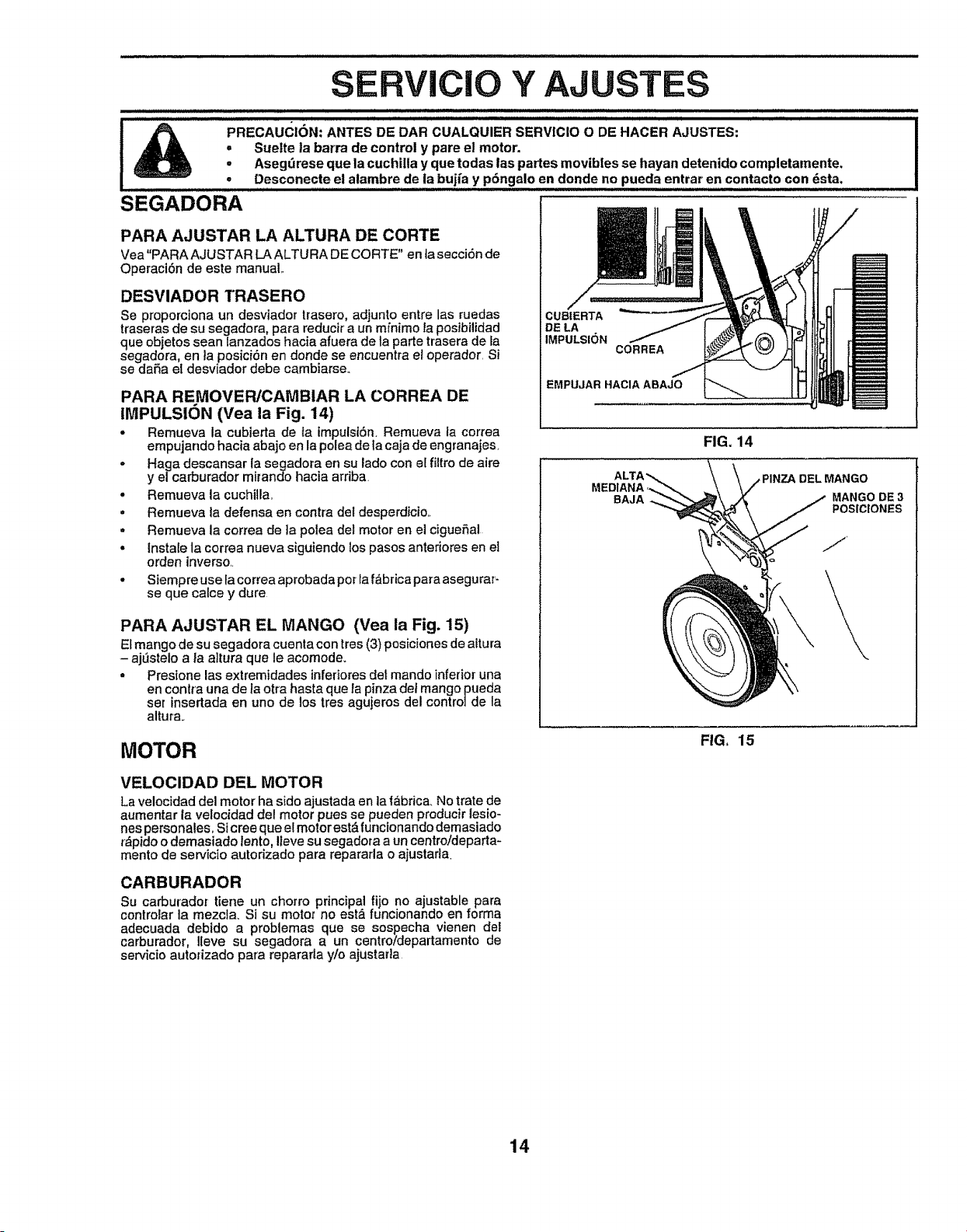
SERVIC Y AJUSTES
PRECAUCION: ANTES DE DAR CUALQUIER SERVICIO O DE HACER AJUSTES:
• Suelte ta barra de control y pare el motor'.
a
o
SEGADORA
Asegdrese que la cuchilta y que todas las partes movibles se hayan detenido completamente.
Desconecte el alambre de la bujia y p6ngalo en donde no pueda entrar en contacto con dsta,
PARA AJUSTAR LA ALTURA DE CORTE
Vea"PARA AJUSTAR Elk ALTURA DE CORTE" en ta secci6n de
OperaciSn de este manual,.
DESVIADOR TRASERO
Se proporciona un desviador trasero, adjunto entre las ruedas
traseras de su segadora, para reducir a un mfnimo ta posibilidad
que objetos sean lanzados hacia afuera de ta parte trasera de Ia
segadora, en la posici6n en deride se encuentra et operador. Si
se da_a el desviador debe cambiarse.,
PARA REMOVER/CAMBIAR LA CORREA DE
IMPULSION (Vea la Fig. 14)
• Remueva la cubierta de la impulst6n, Remueva ia correa
empujando hacia abajo en la polea de ta caja de engranajes,
° Haga descansar la segadora en su lade con el filtro de aire
y e/carburador mirando hacia arriba
• Remueva la cuchitla,
• Remueva la defensa en contra del desperdicio.,
= Remueva la correa de ]a polea del motor en e] cigueSal
• Instate la correa nueva siguiendo los pasos anteriores en el
orden inverse,.
° Siempre use ta correa aprobada per Iaf_brica para asegurar-
se que calce y dure
PARA AJUSTAR EL MANGO (Vea la Fig. 15)
Et mango de su segadora cuenta con tres (3) posicionesde attura
- air,stele a la aitura que le acomode.
- Presiene las extremidades inferioresdet mando inferior una
en contra una de la otra hasta que la pinza def mango pueda
set insertada en uno de los ires agujeros del centre|de ta
altura_
MOTOR
CUBIERTA
DE LA
IMPULSION
CORREA
EMPUJAR HACIA ABAJO
FIG. 14
BAJA
MANGO DE 3
POSICtONES
FIG, 15
VELOClDAD DEL MOTOR
La velocidad del motor ha side ajustada en la fabrica. No trate de
aumentar la velocidad del motor pues se pueden producirlesio-
nes personales, Si cree que el motorestd funcionandodemasiado
r_pido o demasiado lento Ileve su segadora a un centro/departa-
menlo de servicio autodzado para repararla o ajustar a.
CARBURADOR
Su carburador tiene un chorro principal fijo no ajustable para
controiar la mezcla. Si su motor no est_ funcionando en forma
adecuada debido a problemas que se sospecha vienen del
carburador, Ileve su segadera a un centro/departamento de
servicio autorizado para repararla y/o ajustarla
14
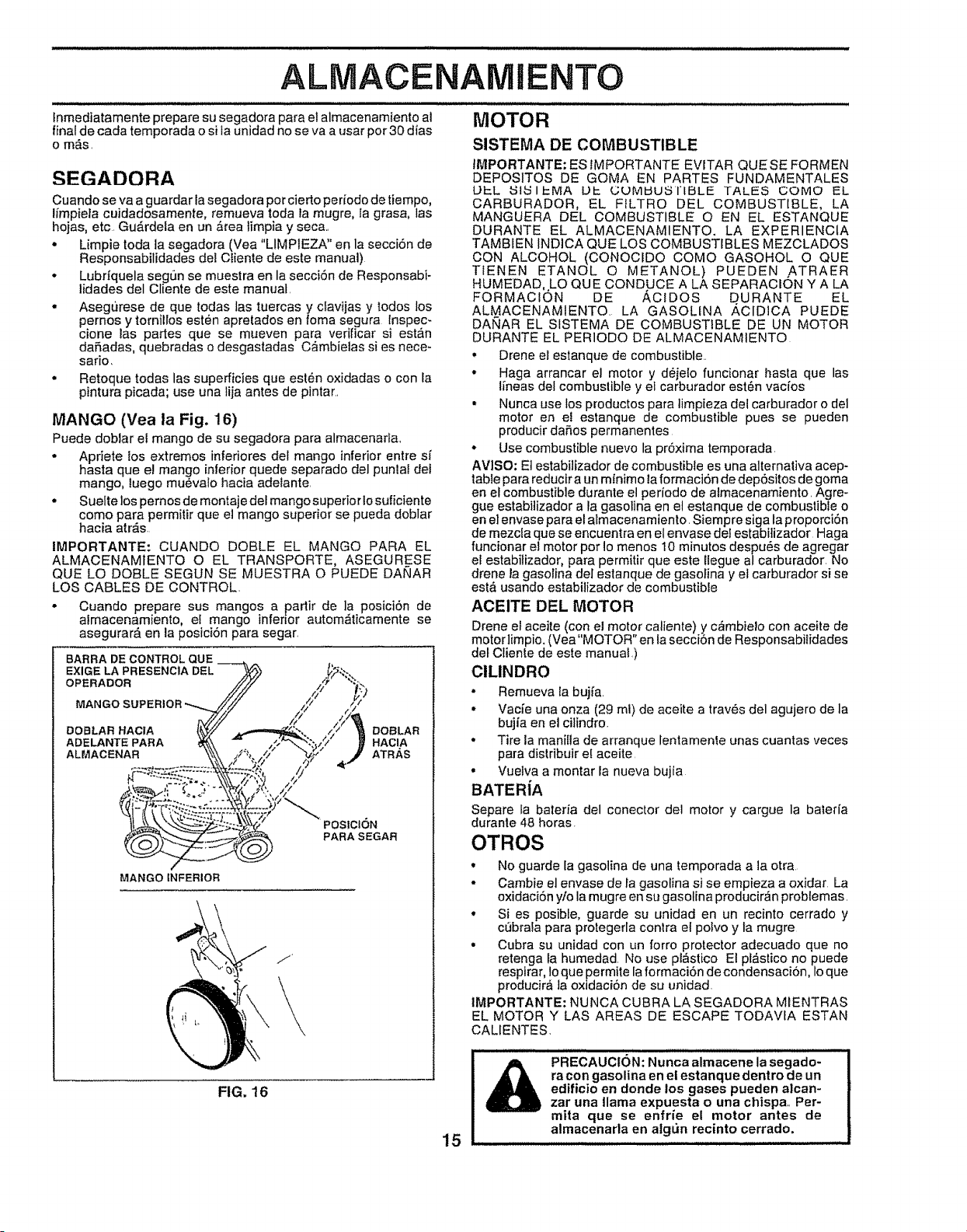
ALMACENAMIENTO
tnmediatamente prepare su segadora para el almacenamiento al
final de cada temporada o si la unidad no se va a usar por 30 dias
o m_s.
SEGADORA
Cuando se va a guardar la segadora por eierto periodode tiempo,
Ifmpiela cuidadosamente, remueva toda la mugre, la grasa, las
hojas, etc. GuArdela en un _rea limpia y seca..
* Limpie toda ta segadora (Vea "LIMPIEZA" en la secci6n de
Responsabilidades del Cliente de este manual)
. Lubriquela seg0n se muestra en la secci6n de Responsabi-
lidades del Cliente de este manual.
- Asegurese de que todas las tuercas y clavijas y todos los
pernos y tornillos esten apretados en foma segura lnspec-
cione las partes que se mueven para verificar si esta,n
dafiadas, quebradas o desgastadas C_mbielas si es nece-
safio,
, Retoque todas las superficies que esl6n oxidadas o con ta
pintura picada; use una lija antes de pintar..
MANGO (Yea la Fig. 16)
Puede doblar et mango de su segadora para almacenarla..
° Apriete los extremos inferiores del mango inferior entre si
hasta que el mango inlerior quede separado del punla! del
mango, luego muevalo hacia adetante.
° Suelte los pernos de montaje del mango superiorlo suficiente
como para permitir que el mango superior se pueda doblar
hacia arras.
IMPORTANTE- CUANDO DOBLE EL MANGO PARA EL
ALMACENAMtENTO O EL TRANSPORTE, ASEGURESE
QUE LO DOBLE SEGUN SE MUESTRA O PUEDE DANAR
LOS CABLES DE CONTROL.
• Cuando prepare sus mangos a partir de ]a posici6n de
almacenamiento, el mango infen'or autom_ticamente se
asegurar_ en la posici6n para segar.
BARRA DE CONTROL QUE
EXIGELAPRESENC1A DEL
OPERADOR
MANGO
DOBLAR HACIA DOBLAR
ADELANTE PARA HACIA
ALMACENAR ATRAS
POStCI6N
PARASEGAR
MANGO INFERIOR
/'
FIG, 16
15
MOTOR
SISTEMA DE COMBUSTIBLE
IMPORTANTE: ES 1MPORTANTE EVITAR QUE SE FORMEN
DEPOSITOS DE GOMA EN PARTES FUNDAMENTALES
UI::L ISRSIP-MA UP- GUMtdUSIIBLE TALES GOMO EL
CARBURADOR, EL FILTRO DEL COMBUSTIBLE, LA
MANGUERA DEL COMBUSTIBLE O EN EL ESTANQUE
DURANTE EL ALMACENAMIENTO. LA EXPERIENCIA
TAMBIEN INDICA QUE LOS COMBUSTIBLES MEZCLADOS
CON ALCOHOL (CONOCIDO COMO GASOHOL O QUE
TIENEN ETANOL O METANOL) PUEDEN ATRAER
HUMEDAD, LO QUE CONDUCE A LA SEPARACtON Y A LA
FORMACION DE ACIDOS D URANTE EL
ALMACENAMIENTO. LA GASOLINA ACIDICA PUEDE
DANAR EL SISTEMA DE COMBUSTIBLE DE UN MOTOR
DURANTE EL PERIODO DE ALMACENAMIENTO
. Drene el estanque de combustible.
• Haga arrancar el motor y d_jelo funcionar basra que las
Ifneas del combuslible y el carburador est_n vacfos
• Nunca use los productos para limpieza del carburador o del
motor en el estanque de combustible pues se pueden
producir da5os permanentes
• Use combustible nuevo la pr6xima temporada.
AVISO: Et estabilizador de combustible es una alternaliva acep-
table para reducir a un mlnimo la formaci6n de dep6sitos de goma
en el combustible durante el perfodo de almacenamiento. Agre-
gue estabilizador a la gasolina en el estanque de combustible o
en el envase para et almacenamiento. Siempre siga laproporci6n
de mezcla que se encuentra en el envase del estabilizador Haga
funcionar el motor pot Io menos 10 minutos despu_s de agregar
el estabilizador, para permitir que este llegue a/carburador. No
drene la gasolina del estanque de gasolina y el ca_burador si se
est& usando estabilizador de combustible
ACEITE DEL MOTOR
Drene et aceite (con el motor caliente) y c_mbielo con aceite de
motorlimpio. (Vea"MOTOR" en la secci6n de Responsabilidades
del Cliente de este manual.)
ClLINDRO
° Remueva ta bujfa.
• Vacie una onza (29 ml) de aceite a trav6s del agujero de la
bujia en et cilindro.
• Tire la manilla de arranque lentamente unas cuantas veces
para distribuir e! aceite.
• Vuelva a montar la nueva bujia
BATERiA
Separe la bateria del conector del motor y cargue la bateria
durante 48 horas.
OTROS
• No guarde la gasolina de una temporada a la otra
• Cambie el envase de la gasolina si se empieza a oxidar La
oxidaci6n y/o la mugre en su gasolina producir,_n probtemas.
• Si es posible, guarde su unidad en un recinto cerrado y
cebrafa para protegerla conlra el potvo y la mugre
• Cubra su unidad con un forro protector adecuado que no
retenga la humedad. No use p!_stico El plastico no puede
respirar, toque permite la formaci6n de condensaci6n, Io que
producira la oxidaciSn de su unidad.
tMPORTANTE: NUNCA CUBRA LA SEGADORA MIENTRAS
EL MOTOR Y LAS AREAS DE ESCAPE TODAVfA ESTAN
CALIENTES,
_ RECAUCI6N: Nunca almacene la segado-
ra con gasolina en el estanque dentro de un
edificio en donde los gases pueden alcan-
zar una llama expuesta o una chispa, Per-
mira que se enfrie el motor antes de
almacenarla en algtin recinto cerrado,
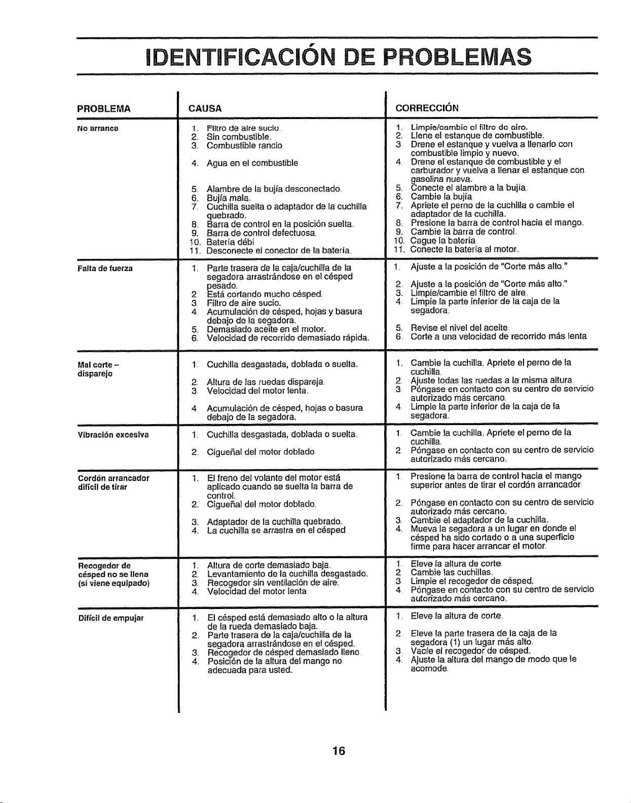
i
f
DE P BLE
PROBLEMA
NO 8rranca
CAUSA
1,. Fit[re de alre sucto.
2. Sin combustible_
3. Combustible ranc]o
4.. Agua en ei combustible
Falta de fuerza
Mal corte-
disparejo
_U_mlUL
Vtbra¢i6n exceslva
Cord6n arrancador
difi'cllde tirar
Recogedor de
c_sped no se Ilena
(st viene equipado)
Difici! de empujar
5. Alambre de labujia desconectado,.
6, Bujfa real&
7, Cuchilta suelta o adaptador de la cuchi]fa
quebrado,
& Barra de control en ta posici6n suelta.
9. Barta de control defectuosa,
tO, Baterla d6bi
11,, Desconecte el conector de la bateria.
1_ Parle trasera de la caja/cuchilfa de la
segadma arrastr,:4,ndoseen el c@sped
pesado..
2. EstA cortando mucho c_sped.
3. Fiftro de aire sucio,
4 Acumulaci6n de c_sped, hojas y basura
debajo de la segadora,
5. Demasiado aceite en el motor.
6, Velocidad de reco[fido demasiado r_pida,
1.
2,
3
4
i.
Cuchi!]a desgastada, doblada o suelta,,
Altura de las ruedas dispareja
Velocidad del motor lenta,
Acumulaci6n de c_sped, hojas o basura
debajo de la segadora,
Cuchilla desgastada, doblada o suelta.
2. CigueSal del motor doblado
1, Et freno del volante der motor est,_
aplicado cuando se suelta la barra de
control,.
2. CigueSal dei motor doblado
& Adaptador de la cuchNa quebrado,
4, La cuchilla se arrastra en el c6sped
...... corledemas a,Jobal i..........
2. Levantamiento de la cuchitta desgastado..
3, Recogedor sin ventilaci6n de aire_
4_ Velocidad del motor tenta
1.. El c_,sped est_ demasiado alto o la altura
de la rueda demasiado baja.
2. Parle trasera de ]a caja!ouchillade la
segadora arTastr#,ndose en el c_sped.
3. Recogedor de c_sped demasiado Iteno.
4. Posici6n de la altura det mango no
adecuada para uste&
CORRECCION
. Limpie/oembie ct filtro de airo.
,, Llene el estanque de combustible.
3 Drene el estanque y vuelva a Ilenarlo con
combustibletimpio y nuevo.
4 Drene el estanque de combustible y el
carburador y vuelva a llenar el estanque con
gasolina nueva.
5. Conecte el atambre a la bujia.
6,. Cambie la bujia
7.. Apriete el perno de la cuchllla o cambie el
adaptador de ia cuchilla.
8. Presione la barra de control hacia el mango..
9, Cambie la barra de control.
10. Cague fa baterfa
11.. Conecte la bateria al motor..
1,
2,
3_
4.
Ajuste a la posici6n de "Corte mAs alto_"
Ajuste a la posici6n de "Corle m_.s alto.."
Limpie/cambie el filtre de aire..
Limpie la parte inferior- de la caja de la
segadora.
5, Revise el nivel del aceite,
6. Corte a una velocidad de recorrido m_s lenta
1,. Camble la cuchilla, Apriete el pemo de la
cuchilla
. Ajuste todas las ruedas a la misma altura
P6ngase en contacto con su centre de servicio
aulorizado m__scercano,
4 Llmpie la parte inferior de la caja de la
segadora,
1.
2,
2.
3,
4..
1
2
Cambie la cuchilla, Apriete el perno de la
cuchill&
P6ngase en contacto con su centre de servicio
autodzado m__scercano,.
,H,,u JJ
Presione la barra de control hacia el mango
superior antes de tirar el cord6n arrancador.
P6ngase en contacto con su centre de se_vicio
autorizado mAs cercano,.
Cambie el adaptador de la cuchillao
Mueva la segadora a un lugar en donde el
c_sped ha side cortado o a una supedicie
firme para hacer arrancar el motor,
Eleve la altura de corte,
Cambie las cuchillas.
Limpie el recogedor de c_sped,
P6ngase en contacto con su centre de servicio
autorizado m_s cercano,,
Eleve la altura de corte,
2, Eleve la parle trasera de la caja de la
segadora (1) un lugar m_.s alto,
3, Vacfe et recogedor de c_spect,
4. Ajuste la altura del mango de mode que le
acomode
16

NOTAS
17

NOTAS
18

NOTAS
19
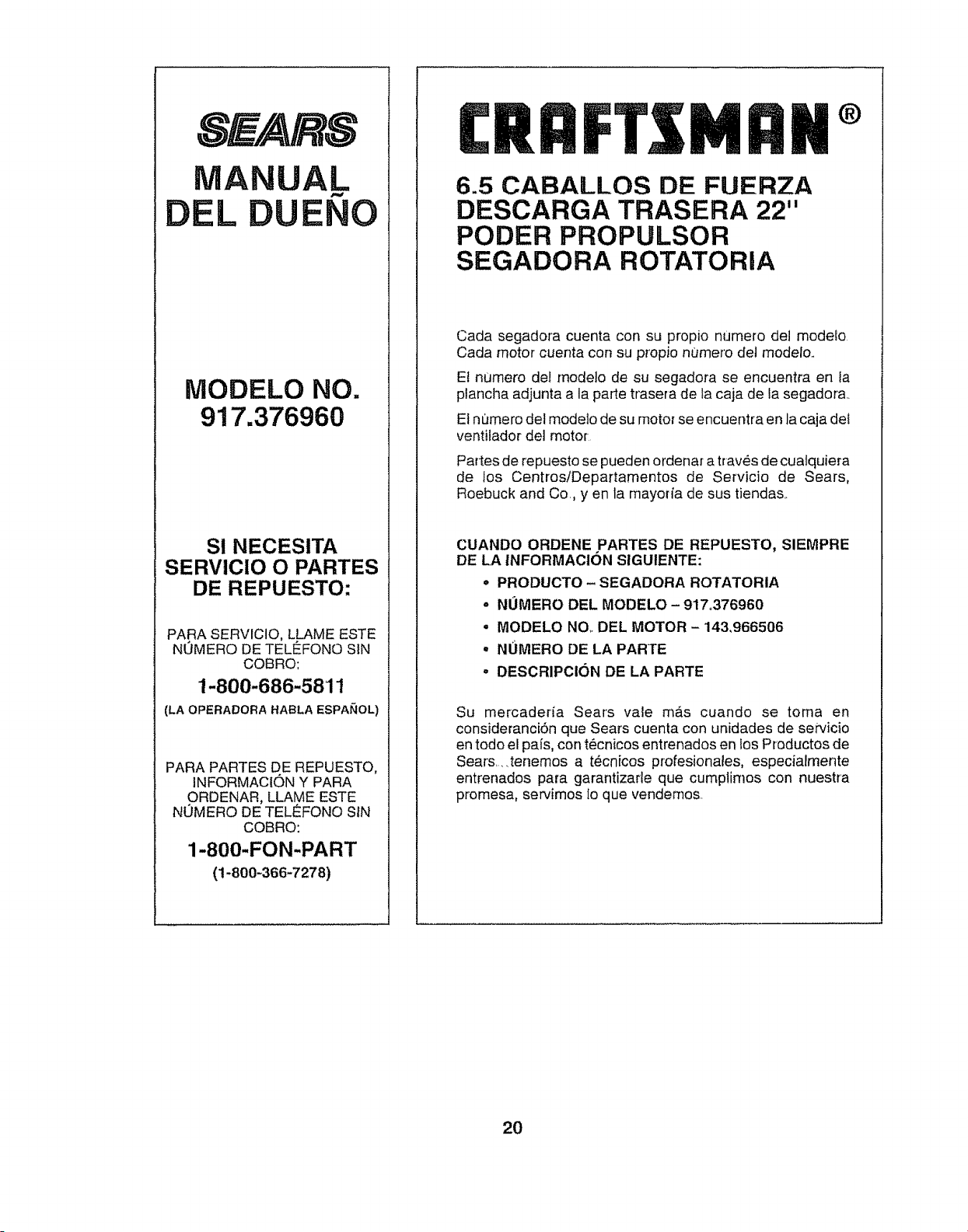
SEA/R8
MANUAL
DEL DUENO
MODELO NO.
917.376960
SI NECESITA
SERVICIO O PARTES
DE REPUESTO:
PARA SERVICIO, LLAME ESTE
NUMERO DE TELE_FONOSIN
COBRO:
1-800-686-5811
(LA OPERADORA HABLA ESPAI_OL)
PARA PARTES DE REPUESTO,
INFORMACION Y PARA
ORDENAR, LLAME ESTE
NUMERO DE TELEFONO SIN
COBRO:
1-800-FON-PART
(1-800-366-7278)
Mnli
6.5 CABALLOS DE FUERZA
DESCARGA TRASERA 22"
PODER PROPULSOR
SEGADORA ROTATORIA
Cada segadora cuenta con su propio numero de1 modeio
Cada motor cuenta con su propio numero det modelo
Et numero del rnodelo de su segadora se encuentra en la
plancha adjunta a la parte trasera de la caja de la segadora_
El numero del modelo de su motor se encuentra en la caja dei
ventifador de] motor
Partes de repuesto se pueden ordenar a trav_s de cuatquiera
de los Centros/Departamentos de Servicio de Sears,
Roebuck and Co, yen la mayorfa de sus tiendas
CUANDO ORDENE PARTES DE REPUESTO, SIEMPRE
DE LA INFORMACION SIGUIENTE:
* PRODUCTO- SEGADORA ROTATORIA
- NOMERO DEL MODELO - 917,376960
, MODELO NQ. DEL MOTOR - 143,966506
° NOMERO DE LA PARTE
° DESCRIPCI(_N DE LA PARTE
Su mercadeda Sears vale mas cuando se toma en
consideranciSn que Sears cuenta con unidades de servicio
en todo e[ pafs, con t_cnicos entrenados en iosProductos de
Sears,_tenemos a tecn[cos profesionales, especiarmente
entrenados para garantizarle que cumptimes con nuestra
promesa, servimos Io que vendemos
2O