Loading ...
Loading ...
Loading ...
14
AUXILIARY CONTROLS
WALL THERMOSTAT TERMINAL
NOTE: Carrier thermostats are recommended.
IMPORTANT: Only trained, qualified personnel
should access electrical panel on unit and install
electrical accessories. Please contact your local
electrical contractor, dealer, or distributor for
assistance.
Thermostat Wire
Routing
Thermostat wire is field supplied. Recommended
wire gauge is 18 to 20 gauge solid thermostat wire.
NOTE: It is recommended that extra wires are run to
unit in case any are damaged during installation.
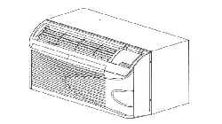
Thermostat wire should always be routed around or
under, NEVER through, the wall sleeve. The wire
should then be routed behind the front panel to the
easil y access ibl e term in al connect or.
THERMOSTAT WIRE ROUTING
(UNDER SLEEVE, BEHIND FRONT PANEL)
A07074
Fig. 22 – Proper Wire Routing Beneath Unit
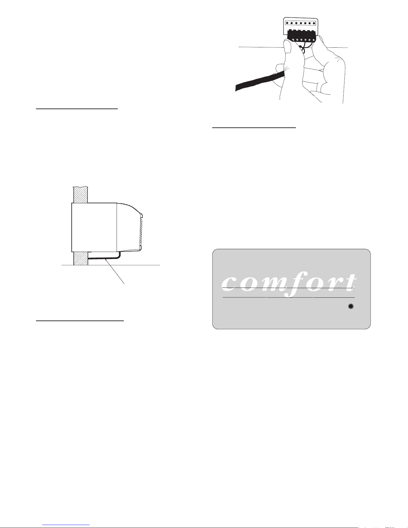
Wiring Thermostat To Unit
Wire wall thermostat input as defined in F ig. 26.
NOTE: Terminal connector can be removed and
replaced to simplify the wiring.
NOTE: For heat pump models, anytime there is a
second--stage call for heating from the wall
thermostat, the unit will automatically switch over to
electric heating.
R W Y O Gh Gl C
A07073
Fig. 23 – Terminal Connector Removal and Replacement
Install Thermostat Wiring
1. Check to be sure power to unit is disconnected.
2. Pull terminal connector to remove
NOTE: Terminal connector can be removed and
replaced to simplify thermostat wiring.
3. Connect wires from the thermostat to terminals
on unit terminal connector.
4. Reinstall terminal connector.
5. Ensure that unit is cofigured for wall thermostat
enable.
6. Replace control panel label with wall thermostat
label (included). See Fig. 24.
7. Restore power to unit.
W
ALL THERMOST
A
T COMFORT
A07315
Fig. 24 – Wall Thermostat Control Panel Label
NOTE: Refer to thermostat installation instructions
for details on installing wall thermostat.
NOTE: For thermostats that have only one fan speed
output (on or auto), the fan speed is determined by
how the terminal connector is wired. If Low fan is
desired, wire the G output from the thermostat to GL
on the unit’s terminal block. If Hi fan is desired, wire
the G output from the thermostat to GH on the unit’s
terminal block.
NOTE: After proper installation, if your thermostat is
not working properly, refer to the Trouble Shooting
section.
Downloaded from www.ManualsFile.com manuals search engine
Loading ...
Loading ...
Loading ...