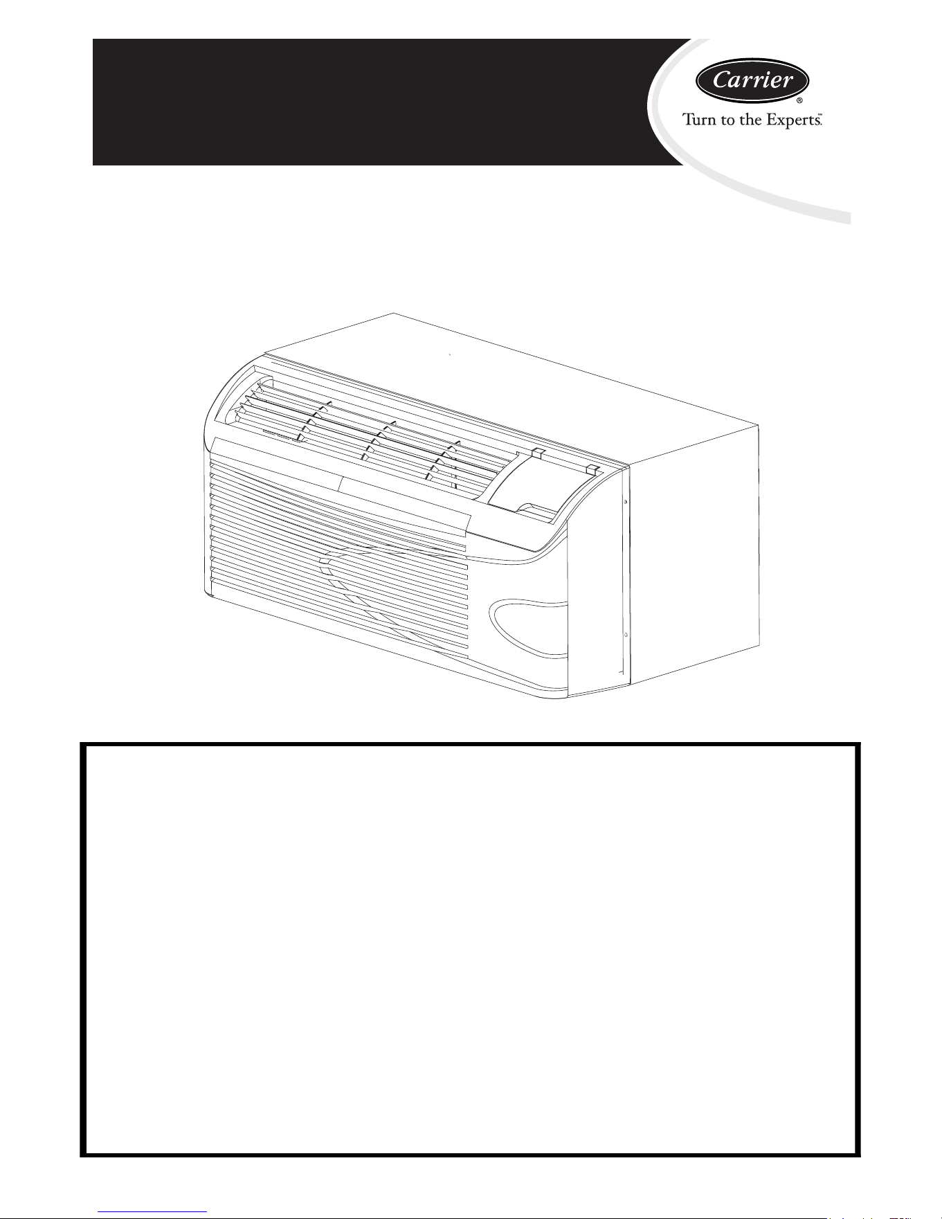
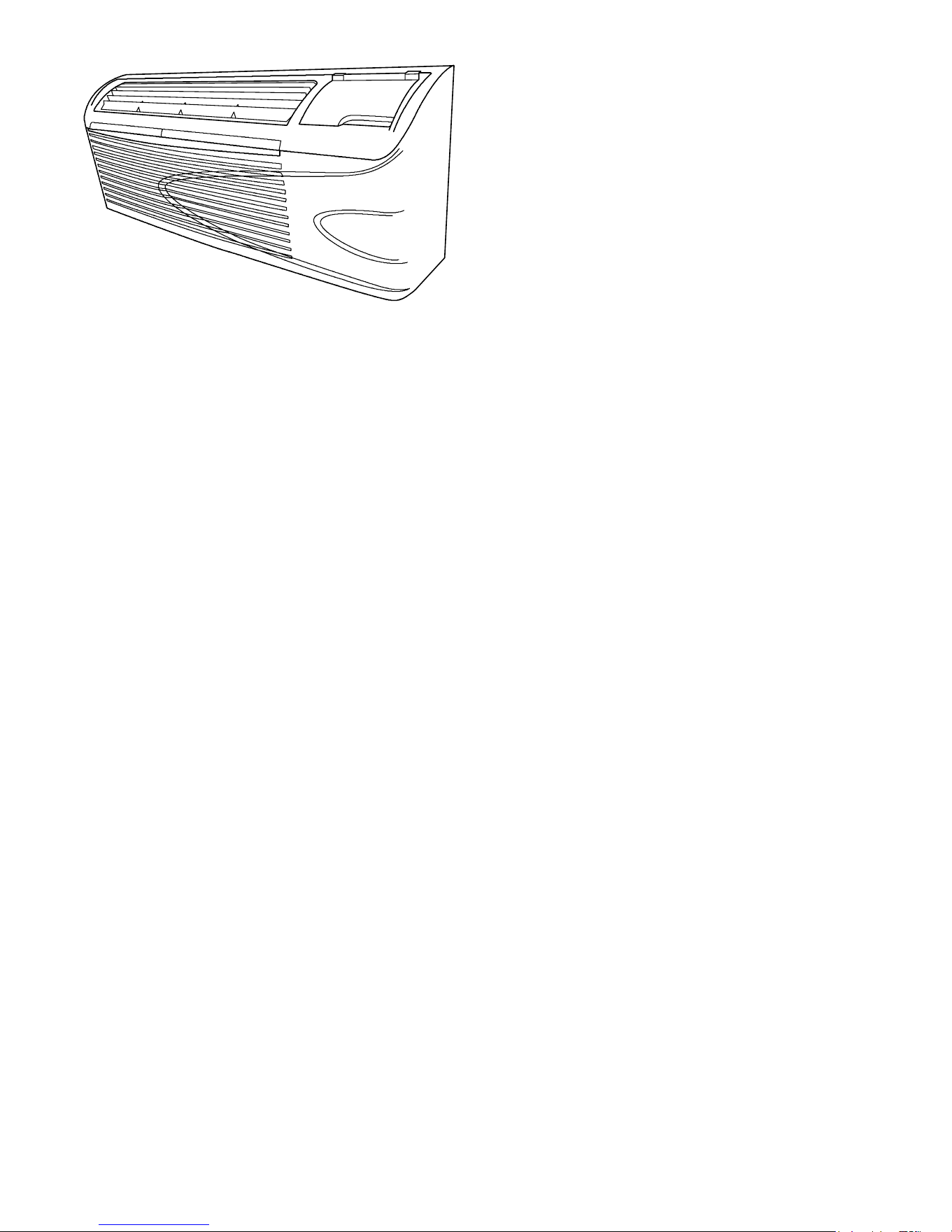
52M Performancet Serie s
P ackaged Terminal Air Conditioner / Heat Pump
7,000 --- 15,000 Bt uh
Installation and Operating
Instructions
A07228
NOTE T O EQUIPMENT OWNER:
Thank you for purchasing a Carrier PTAC. Please read this Owner’s Information Manual carefully
before installing and using this applianc e. Keep this manual for future reference.
For your convenience, please record the model and serial numbers of your new equipment in the
spaces provided. This information, along with the installation data and dealer contact information,
will be helpful should your system require maintenance or service.
UNIT INFORMA TION
Model # ________________________________
Serial # ________________________________
INSTALLA TION INFORMA TION
Date Installed ___________________________
DEALERSHIP CONTACT INFORMATION
Company Name: __________________________________
Address: _________________________________________
_________________________________________________
Phone Number: ________________________________
Technician Name: _________________________________
_________________________________________________
Downloaded from www.ManualsFile.com manuals search engine

2
UNIT INSPECTION
Examine unit for damage incurred during shipment. File a claim immediately with the transit
company if damage is found.
TABLE OF CONTENTS
PAGE
SAFETY CONSIDERATIONS 3...........................................................................
GENERAL INFORMATION. 3............................................................................
UNIT FEATURES 4--5..................................................................................
ELECTRICAL DATA 6..................................................................................
INSTALLATION
Chassis Installation 7.............................................................................
Retrofit Sleeve Preparation 8.......................................................................
Installation of Carrier Wall Sleeve Using Non--Carrier Grille 8.............................................
Install Unit Into Wall Sleeve 9......................................................................
HOW TO CONNECT 10..................................................................................
SYSTEM CONFIGURATION
Ventilation Control 11............................................................................
Adjusting Air Direction 11.........................................................................
Dipswitches 12..................................................................................
Keypad Configuration 13..........................................................................
AUXILIARY CONTROLS
Wall Thermostat T erminal 14 -- 15...................................................................
Energy Management Input 15......................................................................
Intelligent Self--Checking Control 15.................................................................
OPERATION 16........................................................................................
CARE AND CLEANING 17...............................................................................
PREVENTATIVE MAINTENANCE 18......................................................................
TROUBLESHOOTING 19................................................................................
WARRANTY 23 -- 24.....................................................................................
For Service/Technical Assistance
1•800•894•6449 (in USA and Canada)
NOTE: Warranty coverage documented on back page of owners manual
Downloaded from www.ManualsFile.com manuals search engine
3
READ ALL INSTRUCTIONS BEFORE I NSTALLATION OR USE
SAFETY CONSIDERATIONS
Recognizesafetyinformation. This is the safety-- alert
symbol
. When you see this symbol on the unit and
in instructions or manuals, be alert to the potential for
personal injury.
Understand these signal words: DANGER,
WARNING, and CAUTION. Thes e words are u sed
with the s afety--alert symbol. DANGER identi fies the
mos t serio us hazards which will result in severe
perso nal injury ord eat h. WARNINGsi gn i fi eshazards
which cou l d result in personal injury or death.
CAUTION i s used t o i den ti fy unsafe pract i ces wh ich
may result in minor personal i njury or product and
property damage. NOTE is used to highlight
suggestions which will result in enhanced
installation, reliability, or operation.
PERSONAL INJURY AND/OR PROPERTY DAMAGE
HAZARD
Failure to follow this warning could result in personal injury,
death and/.or property damage.
For your safety, the information in this manual must be
followed to minimize the risk of fire or explosion, electric
shock, or to prevent property damage, personal injury, or loss
of life.
S This unit must be properly installed in accordance
with the Installation Instructions before it is used.
S Immediately repair or replace all electric service
cords that have become frayed or otherwise
damaged.
S Unplug or disconnect the unit at the fuse box or
circuit breaker before making any repairs.
!
WARNING
NOTE: We strongly recommend that any servicing
be performed by a qualified individual.
GENERAL
Thank you for choosing C arrier ’s best PTAC ever!
You can feel confid ent i n your s electi on becaus e the
same pride in craftsmanship and engineering
knowledge that goes into Carrier equipment at the
Astrodome in Texas, the Sistine Chapel in Rome, the
US Capitol Hall of Congress, and thousands of other
installationsworldwidehasgoneintotheconstruction
of this unit.
Carri er pack age term i n al ai r con di t i o ners an d heat
pumps provide a high standard of quality in
performance, workmanship, durability and
appearan ce as th ey heat an d coo l t h e occup i ed ai r
space year round.
This manual provides information for ease of
installation, operation and maintenance.
All models are designed for through-- the -- wall
installation. Separate installation instructions are
incl uded wit h al l acces s ory com ponents.
BEFORE YOU BEGIN
Read these instructions completely and carefully.
IMPORTANT: Save these instructions for local
inspector’s use.
IMPORTANT: Observe all governing codes and
ordinances.
NOTE TO INSTALLER
Be sure to leave these instructions with the owner.
NOTE TO OWNER
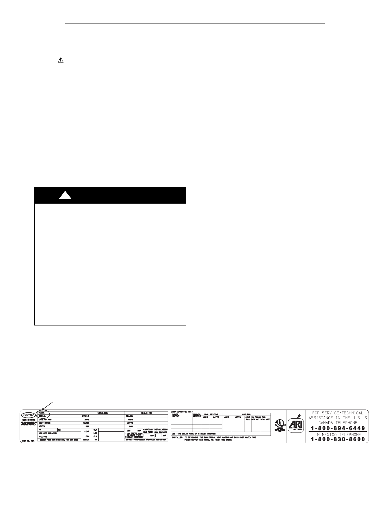
Keep thes e ins t ruct i o ns for fut u re reference. Be su re
to write down t he model and serial number of unit on
space provided on front page. The model and serial
number can be located on the serial number plate
attached to unit. These numbers are required for
servi ce. (See Fi g. 1.)
Save the wall thermostat control panel label to be
placed on con t rol panel in cas e a wal l th ermo s t at is
used or is added in t he future. (See Fig. 24)
Location of Model and Serial Number of Unit
A07229
Fig. 1 – Sample Data Information Plate
Downloaded from www.ManualsFile.com manuals search engine
4
UNIT FEATURES
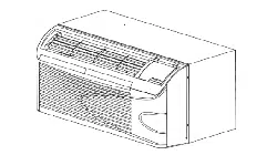
Fig. 2 – Model 52M
This Premium unit has many exciting features which
are different than those found on standard PTAC
models. The owner must be familiar with these
features in order t o fully understand the operation and
capability of the unit.
• Intelligence – Your P remium unit has an on board
computerthat utilizes real timediagnosticstoprolong
the life of your unit. There is an LED indicator on the
control board, behind the front panel, that will flash
an error code if the unit has detected some kind of
fault condition. In many cases, the unit will
automatically clear the fault condition and continue
operating with no interruption. In some cases, the
condition cannot be cleared and the unit will require
servi ce. In th os e cas es , an “Fx” fai lu re m o de wi ll be
displayed on the digital display. For a detailed list of
all error codes and “Fx” conditions, see Table 6 --
Status LED Indicator Definitions for further details.
• Memory – Your Premium unit also has memory. If
power is lost, all of the control settings (setpoint,
mode, fan speed, on/off and configuration) are
remembered. So when power is restored, the unit will
start back up in the mode (and configuration) it was
in, when power was lost.
• Premium Sound – Your Premium unit is also
Carrier’s quietest PTAC ever. Not only does it have 2
fan m otors and a tangential blower wheel for
optimum sound, the indoor fan will always run a
minimum of 10 seconds before the compressor, to
help reduce any compressor starting noise.
• Random Compressor restart -- To help prevent
power s urges after a power out ag e (from man y of
your PTACs starting at the same time), the
compressor is equipped with a 2:45 to 3:15 random
restart delay feature. Whenever the unit is plugged in,
or power has been restarted, a random compressor
rest art wi l l occur.
• Compressor Protection -- To prevent short cycling
of the compressor and maximize it’s life, there is a
random start--up delay of 3 minutes on the
compressor and a minimum compressor run time of 3
minutes.
• Automati c room freeze p rotection –automatically
will keep the temperature in the room from getting
too co l d, where water pip es m i gh t freeze. If t he un i t
is co nfi g u red for t he freeze pro t ecti o n feat u re to b e
active(which is the default condition), then whenever
power is supplied to the unit, if the unit senses
tem perat u re bel o w 40°F, t h e fan mot o r and el ect ri c
heater are turned on and will warm the room to 50_F.
If F r eeze protect i on is not requ i red, ch ang e the
configuration switch to turn the feature off (see
section on unit configuration).
• Au toma ti c defrost protection (for h eat pump
models only) – When the outdoor temperature gets
too cold (approx. 35°F) and the unit can no longer
effectively heat with the compressor, the unit will
automatically switch t o electric heating. Theunit will
then heat wi t h elect ri c heat unt i l th e out s i de
temperature rises enough (approx. 40°F), so the
comp res s or can b e us ed agai n .
• Au to mati c Quick Wa rm --u p (for hea t p u mp
models only) -- If the room temperature falls to 5°F
belo w t he set p oi n t t em perat u re, th e r evers e cycl e
heat is shut off and the electric strip heat is turned on
for one cycl e, unti l heatin g i s s at i sfi ed .
• LED Indicator’s and Buttons -- The touch pad has
buttons for MODE, FANS P EED, ON/OFF,
SETP OINT UP and S ETPOINT DOWN. It also has
LEDs that correspond to the mode, fan speed and
setpoint operation, to indicate t he unit’s status. The
LEDs below the mode button, FAN, C OOL, and
HEAT, indicate what operating mode is active. The
LEDs below the Fan button, Low, Med and Hi,
ind i cat e th e fan sp eed t hat i s s el ect ed . Th e LED
locat ed i n t he lo wer rig h t corn er is t h e uni t On / Off
status LED. If the unit is in ON mode, the LED will
be green. If the unit is OFF, the LED will be red.
• Configure Fan to Optimize Selected Application
-- Unit can be optimized to selected application by
configuring the fan to run in continuous mode or
cycle on and off with the compressor and electric
heater (can be different for bot h heati n g an d cooli n g
modes). In cycle mode, fan will continue to run after
comp res s or or elect ri c heater s t o ps in order bl ow off
any residual heat or cool left on coil.
Downloaded from www.ManualsFile.com manuals search engine

5
UNIT FEATURES CONTINUED
• Unit Configuration – There are m an y di fferent
configuration possibilities, through both dipswitches
and the digital keypad, that allow you to configure
the unit for your exact application. See section on
unit configurationfor more details. Following are the
configurationselectionsthathavenotpreviouslybeen
mentioned:
• _For_C – The unit can display in either _For_C
• Ind oor Temperature Sensor Biasin g – Optimize
the room temperature sensor reading to your exact
application (one for cooling andanother for heating)..
• Emerg en cy Hea t (for H eat Pu mp O n l y) – Disable
the compressor during heating mode operation (heat
onl y wi t h E lect ri c Heat ).
• Disp l ay S etp o i n t OR Room Temp eratu re -- T h e
unit can be configured to display the room
temperature OR setpoint only, during heating and
cooling modes. See section on unit configuration for
more details.
• Limit the Setpoint Range -- The unit can be
configuredto limit thecontrollingsetpoint range.The
displaywill alwaysshow the completesetpointrange,
but the controlling setpoint will be limited to the
configuredminimumandmaximumsetpointselected.
See section on unit configuration for more details.
• Energy Management – S ometimes known as
Front Desk Control, an input is provided so that the
unit can be manually disabled from a different
location. If the unit detects 24vac on this input, it will
automatically turn itself off. If no voltage is detected
on the input, the unit will run normally.
• Wall Thermostat Control –Awiredwall
thermostat can be connected to the unit. If it is, the
unit m ust be configured to disable the keypad. S ee
section on wired inputs and unit configuration for
more details.
Electrical Data
3 – 230/208-v, 60 Hz
4 – 265-v, 60 Hz
Cooling Capacity (nominal)
07 – 7,000 Btuh
09 – 9,000 Btuh
12 – 12,000 Btuh
15 – 15,000 Btuh
52 ME – U 12 – – – 3
Series Designation
PTAC (Packaged Terminal Air Conditioner)
Electric Heater Size
U – Universal (defined by power cord)
Performance Series
ME – Cooling with Electric Heat
MQ – Heat Pump
A07053
Fig. 3 – Catalog Number Nomenclature
Downloaded from www.ManualsFile.com manuals search engine
6
ELECTRICAL DATA
ELECTRICAL SHOCK HAZARD
Failure to follow this warning could result in personal
injury or death and/or property damage
DO NOT alter cord or plug or use an extension cord.
!
WARNING
POWER CONNECTION OPTIONS
Appro pri at e power cord acces so ry ki t is d et erm i ned
by the voltage, and amperage of the branch circuit.
Th e un i t d o es n ot come with a po wer co rd (or
hard wire kit). An accessory power cord k i t m us t
be ordered t o connect the unit to the outlet. If the
uni t is to be hard wired, an access ory hard wire kit
must be ordered.
IMPORTANT: For 265V units, if power cord
accessory option is selected, the cord is only 18”
long and must plug into the accessory electrical
265V subbase.
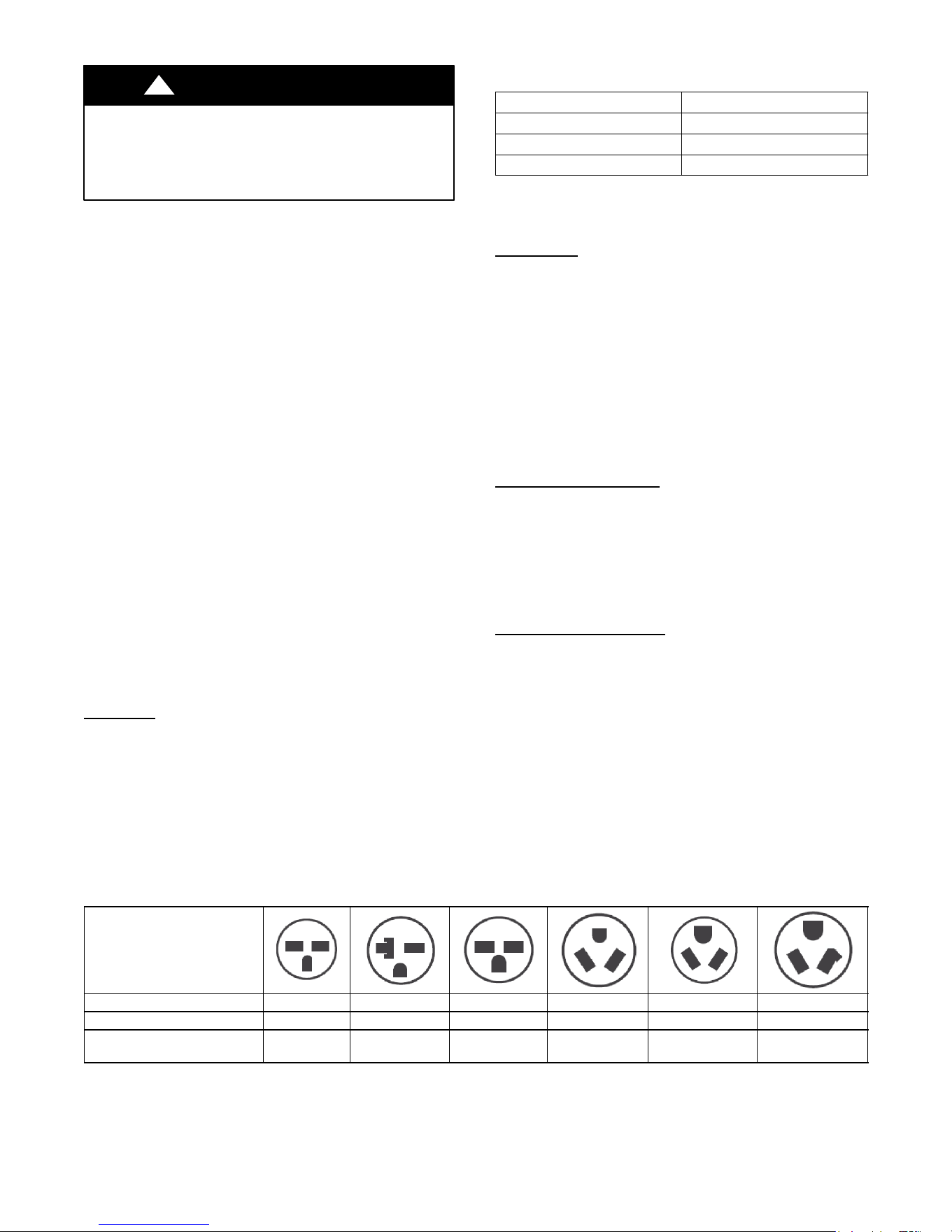
Be sure that your outlet matches the appropriateblade
confi g u rat i on of the p l u g and t h at it is wit h i n reach of
the s ervi ce cord .
All wi ri n g, in clu d i ng in s t al lat i o n of th e receptacl e,
mus t be in accordance wi t h the NEC an d l ocal codes,
ordinances and regulations. National codes require
the us e o f an arc faul t or leak age current det ect io n
device on all 208/230V power cords. Be sure to select
the correct cord for your installation.
ALL UNITS
Wire Size
Use recommended wire size given in Table 1 and
install a single branch circuit. All wiring must
comply with local and national codes. All units are
des i gn ed to o p erate off O NE s i n g le b ranch ci rcui ts
only.
NOTE: Use copper conductors only.
Table 1—SUGGESTED BRANCH CIRCUIT WIRE SIZES*
NAMEPLATE AMPS
AWG WIRE SIZE{
7.0 to 12 14
12.1 to 16 12
16.1 to 24 10
LEGEND
AW G --- A m e r ic a n W i r e G a u g e
* Single circuit from main box.
{ Based on copper wire at 60_C temperature rating.
Grounding
For safety and protection, the unit is grounded
through the service cord plug or through separate
ground wire provided on hard wired units. Be sure
that the branch circuit or general purpose outlet is
grounded.
VOLTAGE SUPPLY
Check voltage supply at outlet. For satisfactory
results, the voltage range must always be within the
ranges found on the data i nformation plate.
Cord--connected
Units
The 250-- v field supplied outlet must match the plug
for t he s tandard 208/230 --v unit s and be withi n reach
of th e servi ce cord . The st an dard co rd--con n ect ed
265 --v uni ts requi re an access o ry elect ri cal subbase
for operat i o n. Refer t o Table 2 f or proper recept acl e
and fuse type.
Power Cord
Protection
The power cord for 230/208v units provide power
cord fire p rot ect i on . Unit power automatically
disconnects when unsafe conditions are detected.
Power to the unit can be restored by pressing the reset
buttononplughead.
Upon completion of unit installation for 230/208V
models, an operational check should be performed
using the TES T/RESET buttons on the plug head.
NOTE: The 265v models do not incorporate this
feature as they require use of the electrical subbase
accessory.
Table 2—RECEPTACLES AND FUSE TYPES -- 250, 265 VOLTS
RECEPTACLE
AMPS 15 20 30 15 20 30
RATED VOLTS 250 250 250 265 265 265
T I M E --- D E L A Y T Y P E F U S E
(or HACR Circuit Breaker)
15 20* 30 15 20 30
LEGEND
HACR --- Heating, Air Conditioning, Refrigeration
* May be used fro 15--- amp applications
Downloaded from www.ManualsFile.com manuals search engine
7
INSTALLATION
Proper installation is the responsibility of the
installer.
Product failure due to improper installation is not
covered under the Warranty.
CHASSIS INSTALLATION
Units are shipped without a sleeve. In applications
where un i t is a repl acem en t, it is reco m m end ed t h at a
Carri er sl eev e be used .
Thes e uni t s can ret ro fi t Gen eral E lect ri c, Aman a,
Trane, and Friedrich sleeves/grilles (be sure outdoor
grille is installed on the sleeve). See Table 3 for
details. Carrier Corporation must approve any other
retrofit application.
For competitive retrofit applications, be sure that the
foam s eal s (fact o ry--i n st al l ed o n the t u be sheet s)
provide a good seal between the grille and outdoor
coil t ub e sheet s . Th ese foam seal s prov i de a b arri er to
separate outdoor coil leaving air from mixing with
the outdoor incoming air (known as air
recirculation).
UNIT DAMAGE AND/OR OPERATION HAZARD
Failure to follow this caution may result in equipment
damage or improper operation.
For retrofit applications, foam seals on outdoor coil tube
sheets must make a seal between the coil and the grille or
loss of performance and premature damage to the major
components can result.
CAUTION
!
Table 3—Retrofit W all Sleeves
Manufacturer
Wall Sleeve Part Number
General Electric Metal Sleeve RAB71
Plastic Sleeve RAB77
Amana Metal Sleeve WS900B
Trane Metal Sleeve SLV149
F riedrich T --- S e r i e s M e t a l 1 1
1/2
--- i n . D e e p Wa l l
Sleeve*
Standard Depth Wall Sleeve
16 X 42 X 13
3/4
--- i n . P X W S
* FR---SLEEVE ---EXT accessory is required for retrofit into Friedrich
(T---Series) wall sleeves.
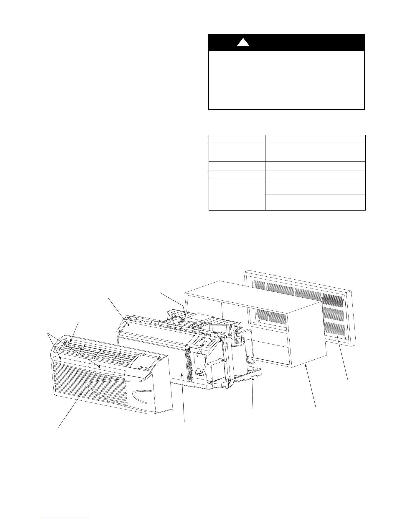
FRONT
PANEL
INDOOR
COIL
BASEPAN
DISCHARGE
GRILLE
WIRE SCREEN
OUTDOOR
ORIFICE
COIL TUBE
SHEETS
INDOOR-AIR
INLET
FILTERS
ACCESSORY
WALL
SLEEVE
ACCESSORY
OUTDOOR
GRILLE
A06752
Fig. 4 – Unit Components
Downloaded from www.ManualsFile.com manuals search engine
8
RETROFIT SLEEVE PREPARATION
IMPORTANT: Inspect wall sleeve thoroughly
prior to in s tallation. Manufacturer does not
assume responsibility for costs or damages due to
defects in sleeve or for improper installation.
ELECTRICAL SHOCK HAZARD
Failure to follow this warning could result in personal injury
or death.
Disconnect all power to unit to avoid possible electrical shock
during installation.
!
WARNING
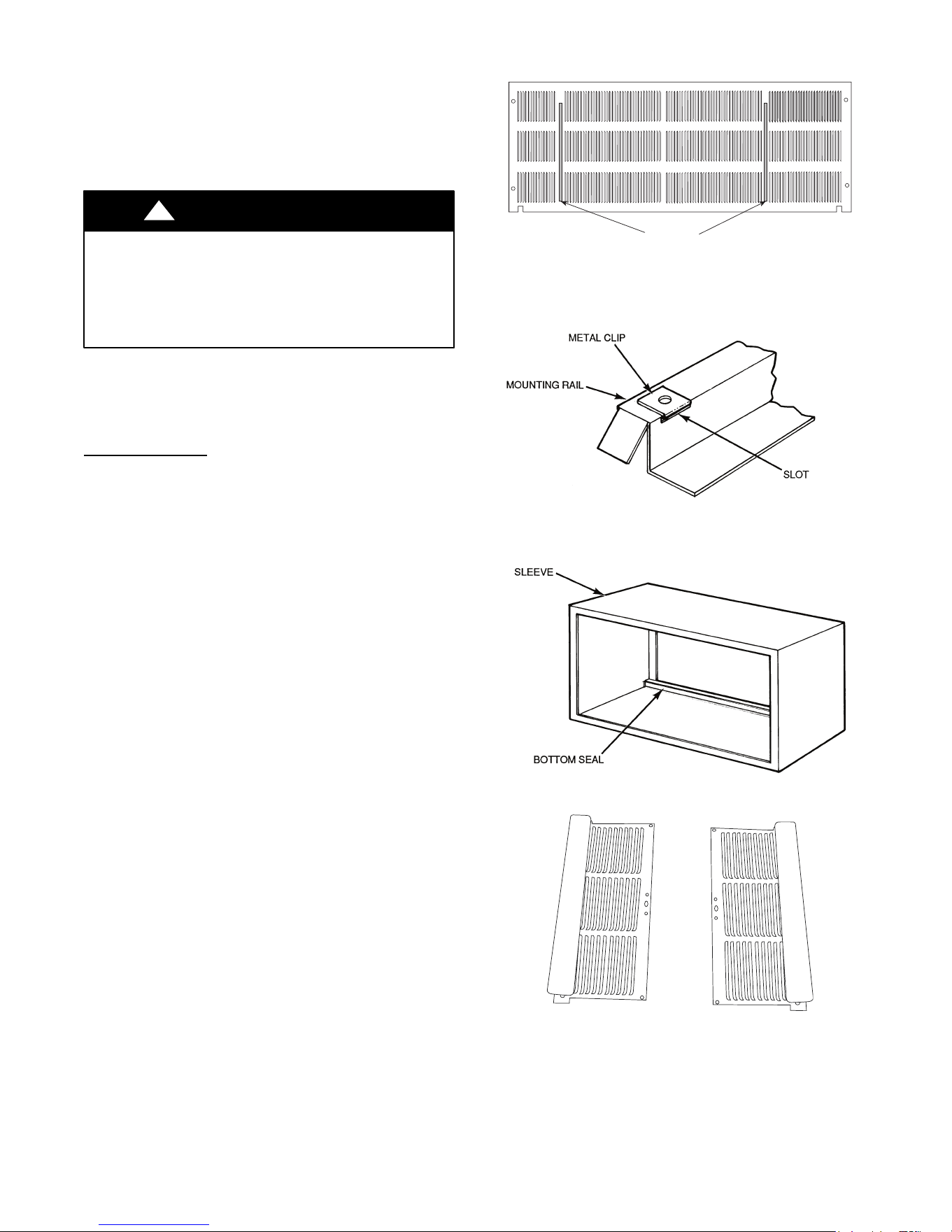
Remove any existing foam baffles that are installed
on competitive outdoor grille, if present. See F ig. 5.
GE Sleeves
Only
GE Meta l Wall S l eeve -- Remove metal clip on
mounting rail located on left, inside bottom, of metal
sl eeve and d i s card. See Fi g . 6.
GE Plastic Sleeve -- Remove bottom seal from
pl ast i c s l eeve. See Fi g . 7.
INSTALLATION OF A CARRIER WALL
SLEEVE USING A NON--CARRIER
GRILLE
This application has become more common due to
pre--manufactured windows with built -- in grilles or
renovations where a Carrier sleeve is used with an
existing non --Carrier grille.
Use of a Carrier wall sleeve with a non-- Carrier grille
requires installation of an Accessory Baffle Kit (see
Fig. 8), which ensures a good seal between the unit
and exterior grille to prevent air recirculation. Air
recirculation is a large contributor to performance
loss and premature damage to major components.
BAFFLES
A07054
Fig. 5 – Remove Existing Outdoor Grille Baffles on
Competitive Grille
A07055
Fig. 6 – Remove Metal Clip on GE Metal Sleeve
A07056
Fig. 7 – Remove Bottom Seal From GE Plastic Sleeve
A07275
Fig. 8 – Accessory Baffle Kit
Downloaded from www.ManualsFile.com manuals search engine

9
INSTALL UNIT I NTO WALL SLEEVE
1. Carefully remove shipping tape from the front
panel and vent door. See
Fig. 9.
2. Remove shipping screw from the vent door, i f
present. See Fig. 10.
3. Remove front panel. See Fig. 11.
4. Lift unit level and slide unit into wall sleeve
until foam seal rests firmly against front of wall
sleeve.
5. Secure with four screws (supplied) through the
unit flange holes. See Fig. 12.
6. Reinstall front panel. See F ig. 13.
UNIT DAMAGE HAZARD
Failure to follow this caution may result in equipment
damage or improper operation.
Failure to remove shipping tape and screw will prevent
fresh air vent door from opening and may result in damage
to vent door cable
CAUTION
!
Shipping
tape
A07066
Fig. 9 – Shipping Tape Location
Remove shipping
screw if present
A07067
Fig. 10 – Shipping Screw Location
Pull out at the bottom to release it from the tabs
(1). Then l i ft up (2 ).
A07064
Fig. 11 – Removing Front Panel
A07057
Fig. 12 – Securing Unit
Pl ace tabs ov er top rail (1 ). Pu sh Inward at
bottom until panel snaps into place (2).
A07065
Fig. 13 – Replacing Front Panel
Downloaded from www.ManualsFile.com manuals search engine
10
HOW TO CONNECT
IMPORTANT: Please r ead following electrical
safety data carefully.
!
WARNING
ELECTRICAL SHOCK AND/OR UNIT OPERATION
AND DAMAGE HAZARD
Failure to follow this warning could result in personal injury
or death and/or unit operation and damage.
S Follow the National Electrical Code (NEC) or local
codes and ordinances.
S For personal safety, this unit MUST BE properly
grounded.
S Protective devices (fuses or circuit breakers)
acceptable for unit installations are specified on the
nameplate of each unit.
S Do not use an extension cord with this unit.
S Aluminum building wiring may present special
problems -- consult a qualified electrician.
S When unit is in STOP position, there is still
voltage to electrical controls.
S Disconnect power to unit before servicing by:
1. Removing power cord (if it has one) from wall
receptacle.
2. Removing branch circuit fuses or turning circuit
breakers off at panel.
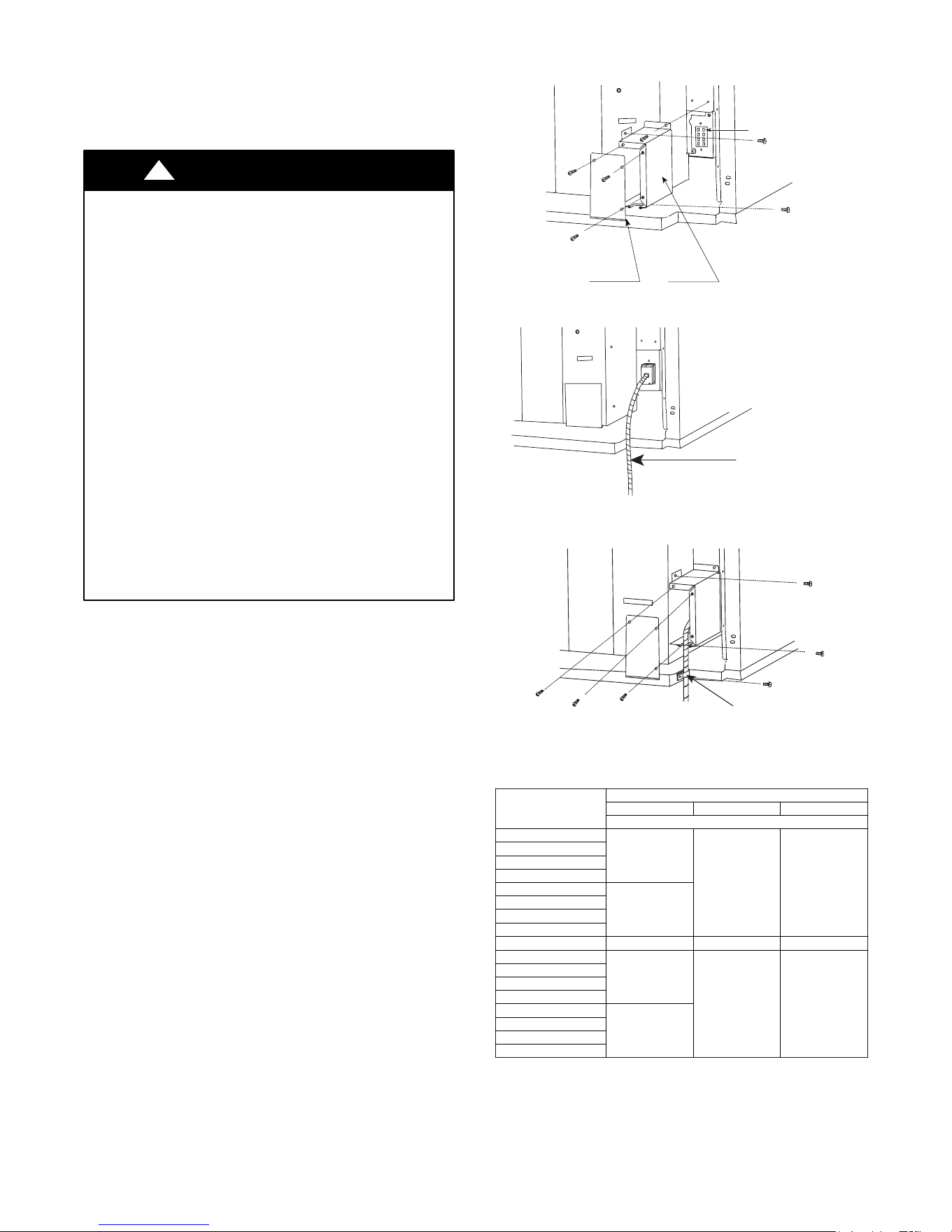
1. Remove front panel. See Fig. 11.
2. Remove junction box.
S Remove junction box cover by removing
three screws from front. Remove junction
box by taking out top, rear and side screws.
See Fig. 14.
3. Connect accessory power supply cord or hard
wire connector to unit connector. See Fig. 15.
S Units must be installed using the appropriate
power supply kit. See Table 4 -- POWER
CONNECTION CHART. These connections
must be followed.
4. Reinstall junction box and cover.
S Use wire clamp to attach power cord to
basepan. Secure with screws (included) See
Fig. 16.
S R elace junction box and cover with screws
removed from Step 2. Tighten securely.
5. Replace front panel. See Fig. 13.
6. Connect power to unit.
Unit connecto
r
Junction box cover
Junction box
A07058
Fig. 14 – Junction Box Location
Accessory
Power Supply Cord
or Hard Wire
A07059
Fig. 15 – Power Connection
Wire clamp
A07060
Fig. 16 – Wire Clamp
Table 4—POWER CONNECTION CHART
UNIT MODEL
CODE OF POWER SUPPLY KIT
30A 20A 15A
230/208 VOLT
5 2 M E --- U 0 7 --- --- --- 3
N/A*
P W R C O R D ---
230V---20A
P W R C O R D ---
230V---15A
5 2 M Q --- U 0 7 --- --- --- 3
5 2 M E --- U 0 9 --- --- --- 3
5 2 M Q --- U 0 9 --- --- --- 3
5 2 M E --- U 1 2 --- --- --- 3
P W R C O R D ---
230V---30A
5 2 M Q --- U 1 2 --- --- --- 3
5 2 M E --- U 1 5 --- --- --- 3
5 2 M Q --- U 1 5 --- --- --- 3
265 VOL T 265 VOL T 265 VOLT
5 2 M E --- U 0 7 --- --- --- 4
N/A*
P W R C O R D ---
265V---20A
P W R C O R D ---
265V---15A
5 2 M Q --- U 0 7 --- --- --- 4
5 2 M E --- U 0 9 --- --- --- 4
5 2 M Q --- U 0 9 --- --- --- 4
5 2 M E --- U 1 2 --- --- --- 4
P W R C O R D ---
265V---30A
5 2 M Q --- U 1 2 --- --- --- 4
5 2 M E --- U 1 5 --- --- --- 4
5 2 M Q --- U 1 5 --- --- --- 4
* Using 30A on these units could result in damage to your unit.
Downloaded from www.ManualsFile.com manuals search engine
11
SYSTEM CONFIGURATION
VENTILATION CONTROL
The ventilation control lever is located at left side of
unit, behind front panel.
NOTE: The vent door shipping hardware must be
removed before using vent control lever. See
Installation Instructions.
When set at CLOS E, only the air inside the room is
circulated and filtered.
When set at OPEN, some outdoor air will be drawn
into room. This will reduce heating or cooling
efficiency.
En erg y Ti p : K eep t he ven t con t rol at CL OS E . Room
air will be filtered and circulated.
Open
Close
Vent Control
(Pull lever through label
to operate.)
A07068
Fig. 17 – Ventilation Control Location
ADJUSTING AIR DIRECTI ON
To adjust air direction:
1. Remove front panel. See Fig. 11.
2. Remove louver screws that hold louver insert in
place (from back side of front panel). See Fig.
18.
3. Turn louver insert and rotate 180_. See Fig. 19.
4. Replace louver insert.
5. Replace screws and front panel.
Louver screws
Louver screws
A07069
Fig. 18 – Backside of Front Panel
Air discharge upward
Air discharge outward (Default)
A07070
Fig. 19 – Adjusting Louvers
Downloaded from www.ManualsFile.com manuals search engine
12
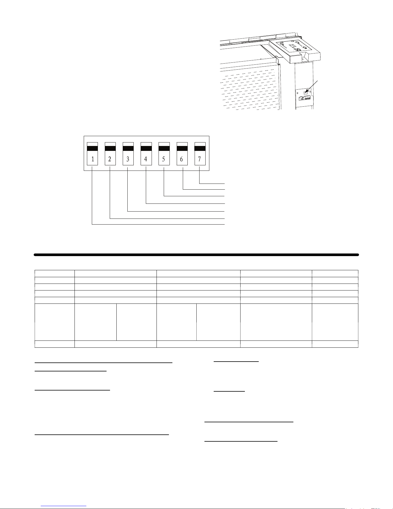
DIP SWITCHES
Auxiliary dip switch controls are located behind front
panel, through an opening below t he control panel.
To access , remove front panel. See Fig . 11.
Dip s wit ches are access ibl e without openi ng the
control box. Unit must be powered OFF to
effectively change their status.
Factory settings for dip switches will be in the
DOWN position. See Table 5 -- Dip Switch
Functions fo r fun cti o ns of each d i p swi t ch p os ition.
Dip Switches
A07071
Fig. 20 – Dipswitch Location on Unit
Electric heat only (for Heat Pumps
)
Wall Thermostat enable
Fan CON/CYC for heating
Fan CON/CYC for cooling
Setpoint Limit 1
Setpoint Limit 2
Freeze guard
Dipswitch
UP
Down
A07072
Fig. 21 – Dip Switches
Table 5—DIP SWITCH FUNCTIONS
No, UP DOWN REMARKS DEFAULT
1 Electric Heat Only Heat Pump For Heat Pump unit only. DOWN
2 Wall Thermostat Enab le Control Panel Enab le DOWN
3 Fan Continuous Run for Heating Fan Cycle for Heat DOWN
4 F an Cycle for Cool Fan Continuous Run for Cooling DOWN
5*6
UP*UP
68---75 _F
20---24 _C
UP*DOWN
63---80 _F
18---28 _C
DOWN*UP
65---78 _F
19---26 _C
DOWN*DOWN
61---86 _F
16---30 _C
(full range)
Two configurations (5*6)
combine to select set point
range.
Whensetpointlimitset,dis-
play always shows full
range.
DOWN*DOWN
61---86 _F
16---30 _C
7 Freeze Guard Disable Freeze Guard Enable DOWN
Electric Heating Only / Emergency Heat (For
Heat Pump Units
Only)
This setting is t ypically used for Emergency Heating.
Wall Thermostat
Enable
A wir ed wal l therm o s t at can be co nn ect ed to the unit .
If it is, this dipswitch must be moved to the Wall
Thermostat Enable Position, before the wall
thermostat will begin control.
Heat and Cool Fan CON/CYC
Dip--switches
Allows the fan to operate in continuous or cycle
modes while the unit is in heating or cooling mode
(continuous or cycle):
CON (Continuous)
Allows fan to run continuously, circulating air even when the
temperature setting has been satisfied. This switch helps to
maintain the room temperature closer to the thermostat setting.
CYC
(Cycle)
This setting allows the fan to cycle on and off with the
compressor or electric heater. The fan stops a short time after
the temperature setting is satisfied.
Setpoint Temperature Limits
Provides a restricted range of temperature control.
Room Freeze
Protection
If unit senses a room temperature below 40°F, the fan
motor and electric strip heat will turn on and warm
the room to 50_F. The fan stops a short time after the
temperature is satisfied.
Downloaded from www.ManualsFile.com manuals search engine

13
KEYPAD CONFIGURATION
Keypad Configuration
Allows further configuration of system to desired
application. Changes do not take affect until power is
cycled on the unit.
To enter Keypad
configuration
Cycle power to unit. P ress and hold the Fan Speed
Button and the C OOLER button for 5 continuous
seconds, within 30 seconds of the unit being powered
up. If the unit has had power for more than 30
continuous seconds, keypad configuration cannot be
entered. When keypad configuration mode is first
entered, it will default to Fahrenheit/ Celsius Display
Mode.
To scroll through the Keypad
Configuration
Options
Press and release the Fan Speed button. The stored
value will be displayed.
To modify configuration
settings
Pres s an d rel eas e th e S et point Up or Setpoint Down
buttons.
To exit Keypad
Configuration
Keypad C onfiguration will end on its own 30 seconds
after the last button press or when the MODE button
on the Keypad is pressed.
Fahrenheit/ Celsius Display Switch
:
Change between degrees Fahrenheit and Celsius on
the display. An “F” indicates Fahrenheit display and
‘C’ i nd i cat es C el s iu s . Default i s deg rees “F ”.
Indoor Air T emperature Sensor Biasing
for
Cooling mode:
Sometimes known as an anticipator, the air
temperature sensor bias is used t o adjust the room air
temperature reading when in cooling mode. (Not
normally required.)
Indoor Air T emperature Sensor Biasing
for
Heating mode:
Sometimes known as an anticipator, the air
temperature sensor bias is used t o adjust the room air
tem perat u re read in g when i n heati ng mode. (Not
normally required.)
Indoor Temperature Display
:
Changebetween showing setpoint only on the display
during heating and cooling modes “SP” or displaying
room temperature during heating and cooling modes
“AA”. “SP” mode is the default mode.
S If “SP” is selected, only the setpoint will be
displayed during heating and cooling modes,
regardless of what the real temperature is in
the room.
S If “AA” mode is selected, the room
temperature will be displayed during heating,
cooling and fan only modes.
— If the mode button has been changed to
either heating or cooling modes, setpoint
will be displayed for 10 seconds. After
the 10 seconds, the room temperature
will again be displayed.
— If the on/off button is depressed (when
the unit is off) and the last mode was
either cooling or heating mode, the
setpoint will be displayed for 10 seconds
before displaying room temperature.
— During heating and cooling modes, if
either the up or down setpoint key is
depressed, the display will show the
setpoint until 10 seconds after the last up
or down key press. Then the room
temperature will be displayed again.
Downloaded from www.ManualsFile.com manuals search engine
14
AUXILIARY CONTROLS
WALL THERMOSTAT TERMINAL
NOTE: Carrier thermostats are recommended.
IMPORTANT: Only trained, qualified personnel
should access electrical panel on unit and install
electrical accessories. Please contact your local
electrical contractor, dealer, or distributor for
assistance.
Thermostat Wire
Routing
Thermostat wire is field supplied. Recommended
wire gauge is 18 to 20 gauge solid thermostat wire.
NOTE: It is recommended that extra wires are run to
unit in case any are damaged during installation.
Thermostat wire should always be routed around or
under, NEVER through, the wall sleeve. The wire
should then be routed behind the front panel to the
easil y access ibl e term in al connect or.
THERMOSTAT WIRE ROUTING
(UNDER SLEEVE, BEHIND FRONT PANEL)
A07074
Fig. 22 – Proper Wire Routing Beneath Unit
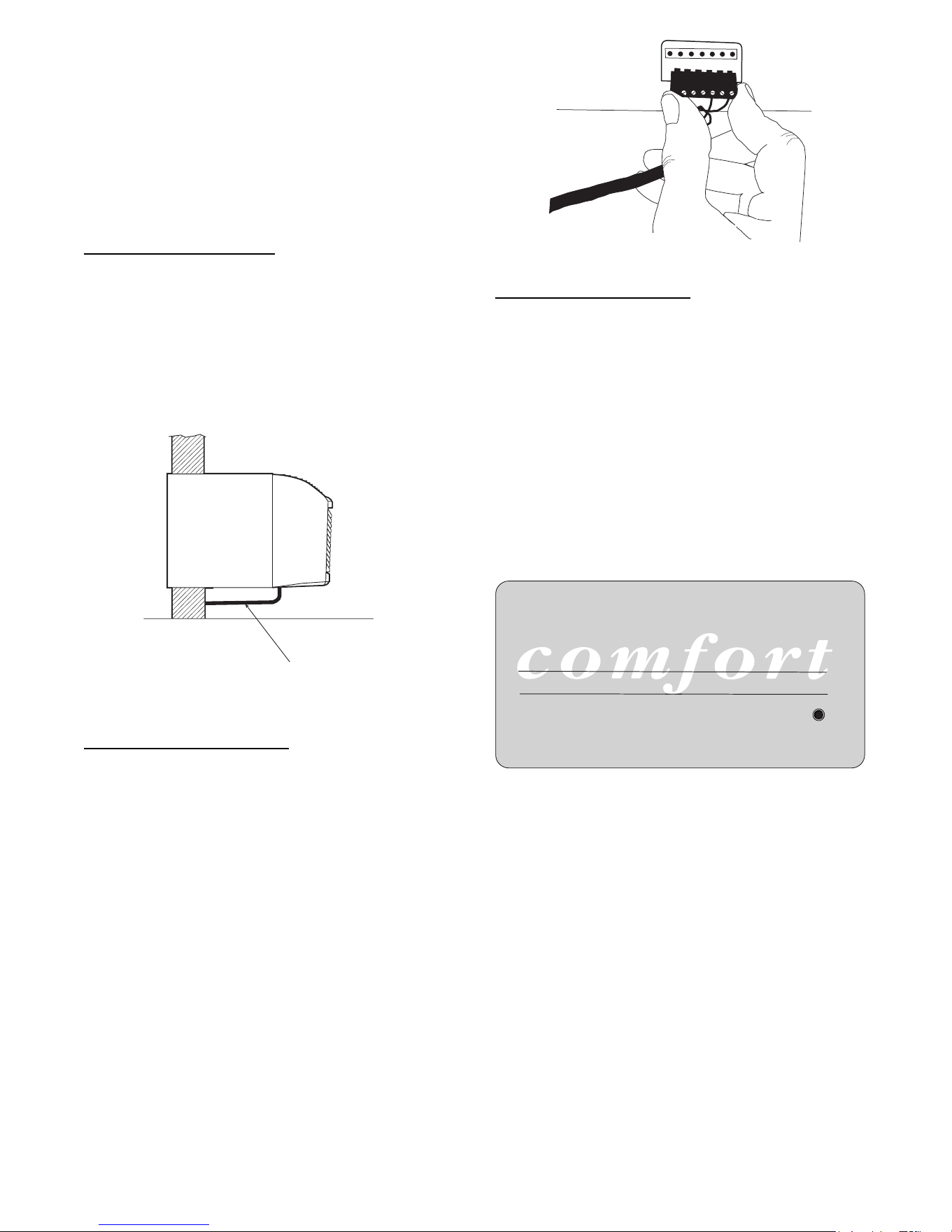
Wiring Thermostat To Unit
Wire wall thermostat input as defined in F ig. 26.
NOTE: Terminal connector can be removed and
replaced to simplify the wiring.
NOTE: For heat pump models, anytime there is a
second--stage call for heating from the wall
thermostat, the unit will automatically switch over to
electric heating.
R W Y O Gh Gl C
A07073
Fig. 23 – Terminal Connector Removal and Replacement
Install Thermostat Wiring
1. Check to be sure power to unit is disconnected.
2. Pull terminal connector to remove
NOTE: Terminal connector can be removed and
replaced to simplify thermostat wiring.
3. Connect wires from the thermostat to terminals
on unit terminal connector.
4. Reinstall terminal connector.
5. Ensure that unit is cofigured for wall thermostat
enable.
6. Replace control panel label with wall thermostat
label (included). See Fig. 24.
7. Restore power to unit.
W
ALL THERMOST
A
T COMFORT
A07315
Fig. 24 – Wall Thermostat Control Panel Label
NOTE: Refer to thermostat installation instructions
for details on installing wall thermostat.
NOTE: For thermostats that have only one fan speed
output (on or auto), the fan speed is determined by
how the terminal connector is wired. If Low fan is
desired, wire the G output from the thermostat to GL
on the unit’s terminal block. If Hi fan is desired, wire
the G output from the thermostat to GH on the unit’s
terminal block.
NOTE: After proper installation, if your thermostat is
not working properly, refer to the Trouble Shooting
section.
Downloaded from www.ManualsFile.com manuals search engine
15
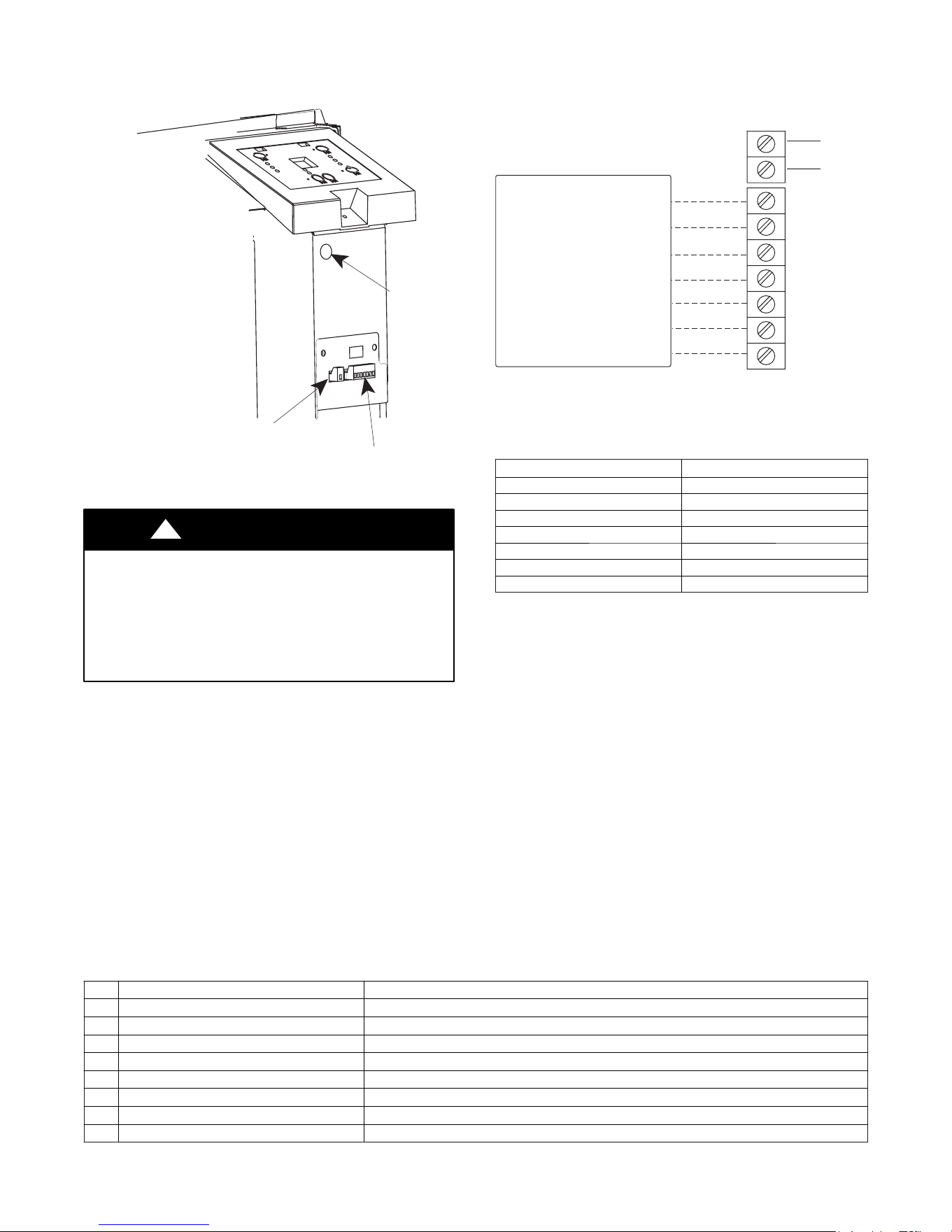
TERMINAL CONNECTIONS
The wall t herm o s t at term i n al bl o ck is l ocat ed beh i nd t he front p anel an d is easi l y access i bl e o n fron t of contro l
panel.
STATUS LED
Wall Thermostat
Terminal Connections
Energy Management
Terminal Connections
A07088
Fig. 25 – Terminal Connector and Status LED Location
UNIT DAMAGE HAZARD
Failure to follow this caution may result in equipment
damage or improper operation.
Improper wiring may damage unit electronics. Common
busing is not permitted. Damage or erratic operation may
result.
CAUTION
!
R
Y
GH
GL
C
W
O
Common
Energy
Management
(24VAC in)
TYPICAL WALL THERMOSTAT
TERMINAL BLOCK
See Note 1
See Note 2
NOTES:
1. Use terminal “O” for heat pump connection only.
2. Terminal “C” (common) is typically only required for digital
thermostats.
A07076
TERMINAL DESIGNATION
R 24 VAC
W Electric Heat
Y Compressor
O Reversing Valve
GH High Fan
GL Low Fan
C Common
NOTE: Any illegal input combinations will be captured as thermostat wiring
failures and will light the STATUS LED indicator on main board
(see I ntelligent Self ---Checking C ontrol section)
Fig. 26 – Wiring Connections
ENERGY MANAGEMENT I NPUT (FRONT DESK CONTROL)
The controller can handle a switch signal from remote energy management input, called EM signal or front desk
control. Input must be 24VAC. If s ystem receives a 24VAC signal , it wil l turn unit off; otherwis e, the unit runs in
normal control . This functi on will be dis abled under Freeze Guard prot ection. See Fig. 25 and F ig. 26 for
terminal connections.
INTELLIGENT SELF--CHECKING CONTROL
Your C arrier PTAC has a computer board that continuously checks key components of t he unit to ensure t hey are
operating properly. Under normal operation, unit status indicator (STATUS, on main PCB), light is steadily ON.
If there is a major problem, the unit will shut down and display a diagnostic failure code on the unit’s display. If
it is only a minor failure and unit is correcting the fault by itself, the diagnostic code will be flashed on the status
LED that can easily be seen when the front panel is removed (see Fig. 25). F ailure STATUS codes are defined in
the table below
Table 6—STATUS LED Indicator Definitions
1 Indoor air temp sensor open/short 7 --- s e g m e n t d i s p l a y ‘F 1’, with STATUS light flash 1 time,off 2 seconds
2 Indoor coil sensor open/short 7 --- s e g m e n t d i s p l a y ‘F 2’, with STATUS light flash 2 time,off 2 seconds
3 Outdoor coil sensor open/short 7 --- s e g m e n t d i s p l a y ‘F4’, with STATUS light flash 4 time,off 2 seconds
4 Freeze Guard protection 7 --- s e g m e n t d i s p l a y ‘FP’
5 Thermostat wiring error STATUS light flash 9 times and off 3 sec, repeat
6 Indoor coil high temp protection STATUS light flash 8 times and off 3 sec, repeat
7 Defrost (heat pump type) STATUS light flash 7 times a nd off 3 sec, repeat
8 Outdoor coil high temp protection STATUS light flash 6 times and off 3 sec, repeat
9 Indoor coil freeze protection STATUS light flash 5 times and off 3 sec, repeat
NOTE: When status light is flashing, it will be ON for 0.5 seconds and OFF for another 0.5 seconds.
Downloaded from www.ManualsFile.com manuals search engine
16
OPERATION
IMPORTANT: When unit is first started, high humidity conditions can cause condensation to form on
discharge grille. Keep doors and windows closed. Room humidity will decrease and moisture will
evaporate.
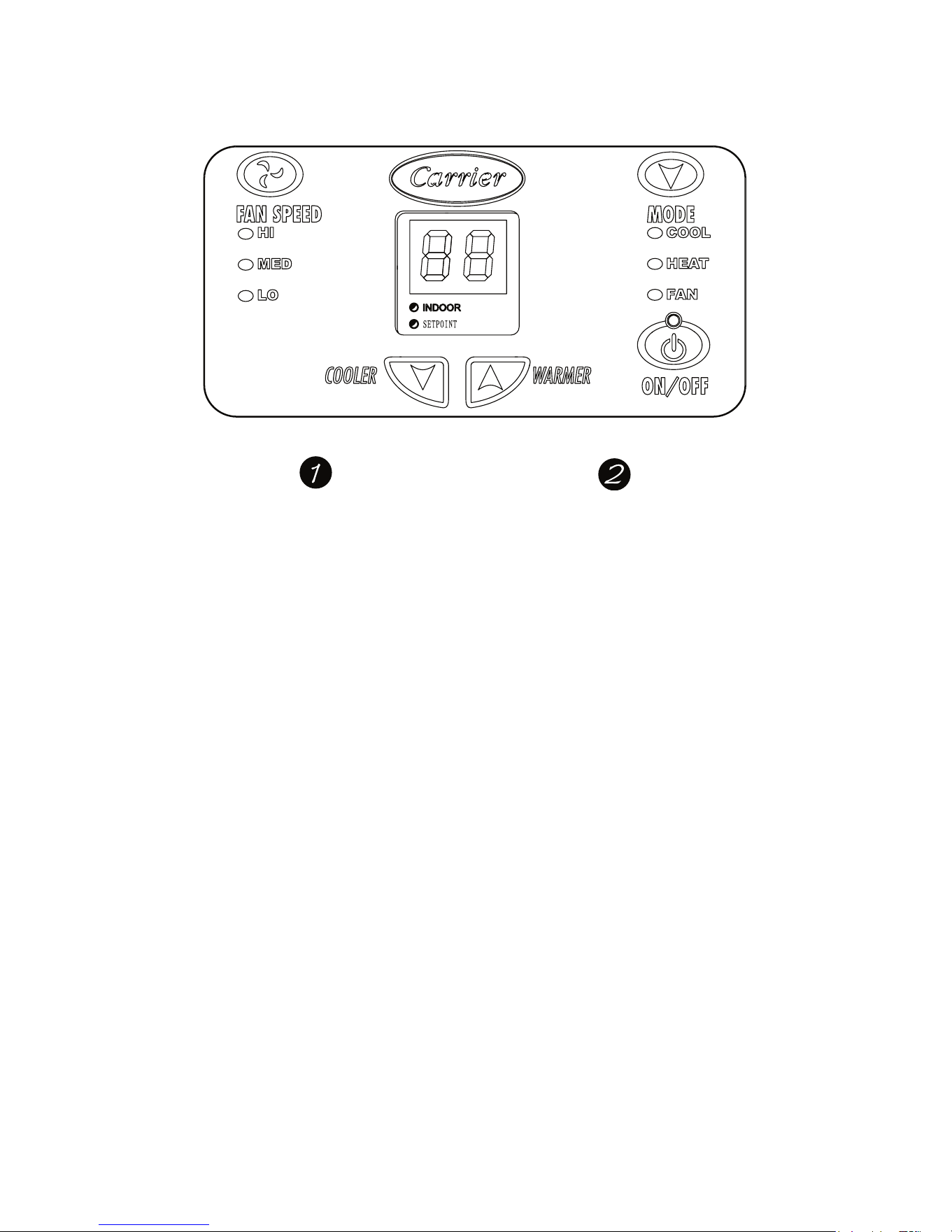
TEMP CONTROL
FAN, MODE& OPERATION
A07061
Fig. 27 – PTAC CONTROLS
ABOUT THE CONTROLS ON YOUR UNIT
NOTE: In case of a power failure, the unit will
r emember the last programmed settings and will
restart to those settings.
1. TEMP CONTROL
Temp Control is used to maintain room temperature.
Co m pres s or wi l l cycle on and off to keep roo m at th e
requested level of comfort.
COOLER -- L owers t em p erat ure.
(Minimum t emperature setting is 61_ F/16_C)
WARMER -- R ai s es t em p erat ur e.
(Maximum temperature setting i s 86_F/30_C)
2. FAN SPEED, MODE & ON/OFF
FAN SPEED -- S et fan operation for HI, MED, or
LO speed.
MODE--CO OL -- For cooling
MODE--H E AT -- For heating
NOTE: If unit is a heat pump, raising the heat setting
5_F will cause unit to use its electric heating
elements for one cycle in order to reach the new
requested temperature quickly.
MODE--FAN -- For fan--only operation
ON/OFF -- Turns the unit on or off.
NOTE: The LED above the ON/OFF button will be
green when unit is ON and red when the unit is OFF.
All other LEDs will be off when unit i s set to OFF
mode.
NOTE: Power remains connected to unit.
Downloaded from www.ManualsFile.com manuals search engine
17
CARE AND CLEANING
FRONT PANEL AND CASE
Turn unit off and disconnect power supply.
To clean, use water and a mild detergent. DO NO T
use bl each or abrasi v es. S om e com m erci al cleaners
may d amag e th e pl as t i c part s.
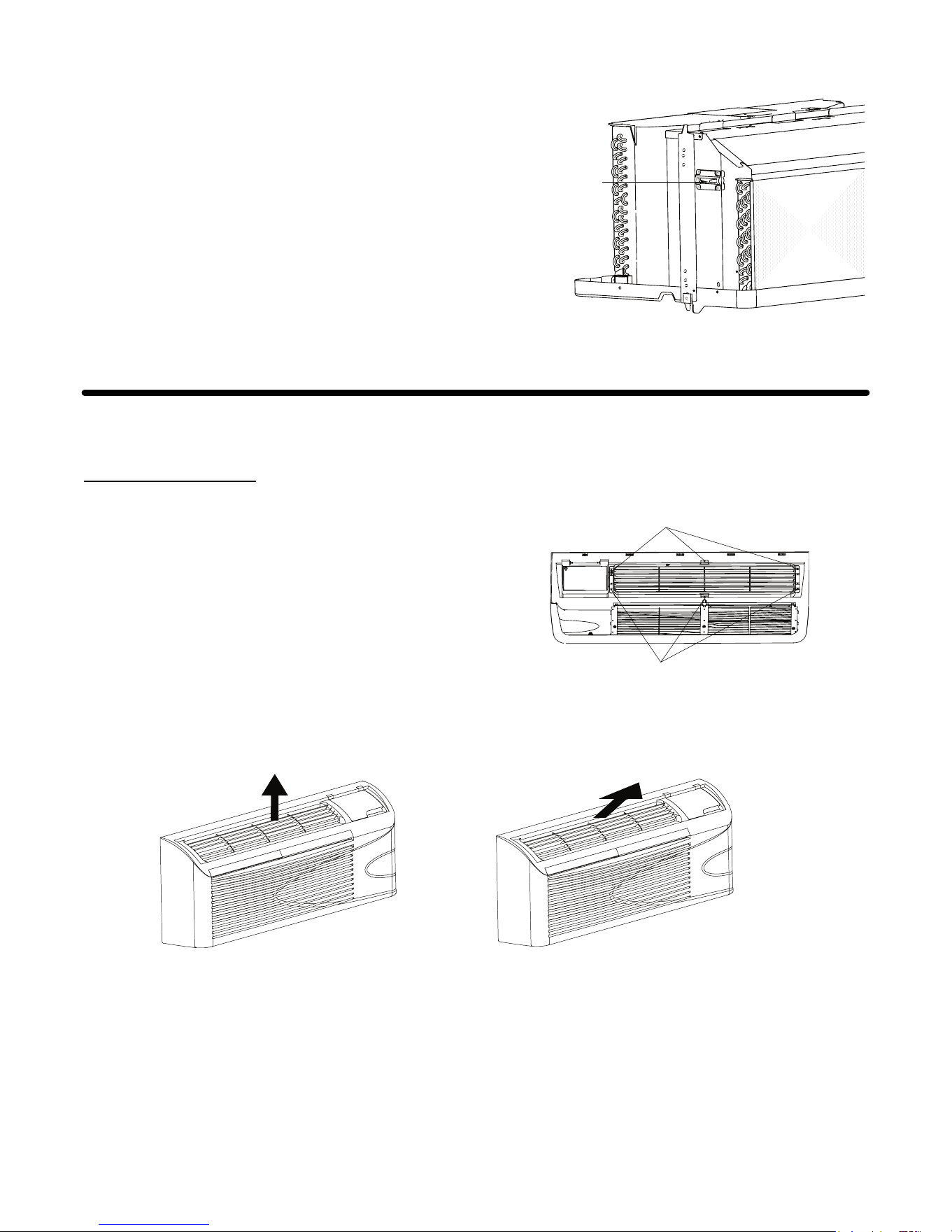
OUTDOOR COIL
Coil on outdoor side of unit should be checked
regularly. Unit will need to be removed to inspect
dirt build -- up that will occur on the inside of the coil.
If clogged with dirt or soot, coil should be
profes s i o nal l y cleaned.
NOTE: Never use a high--pressure spray on coil.
Coils
Grille
Clean inside and outside of outdoor coils regularly
.
A07077
Fig. 28 – Outdoor Coil
UNIT DAMAGE HAZARD
Failure to follow this caution may result in equipment
damage or improper operation.
Airflow restriction may cause damage to the unit.
CAUTION
!
BASE PAN
In some installations, dirt or other debris may be
blown into unit from outside and settle in base pan
(bottom of unit).
In some areas of the United States, a “jell-- like“
sub s t ance m ay b e seen i n t h e bas e pan . Check b as e
pan peri o di cal l y an d cl ean, if necess ary.
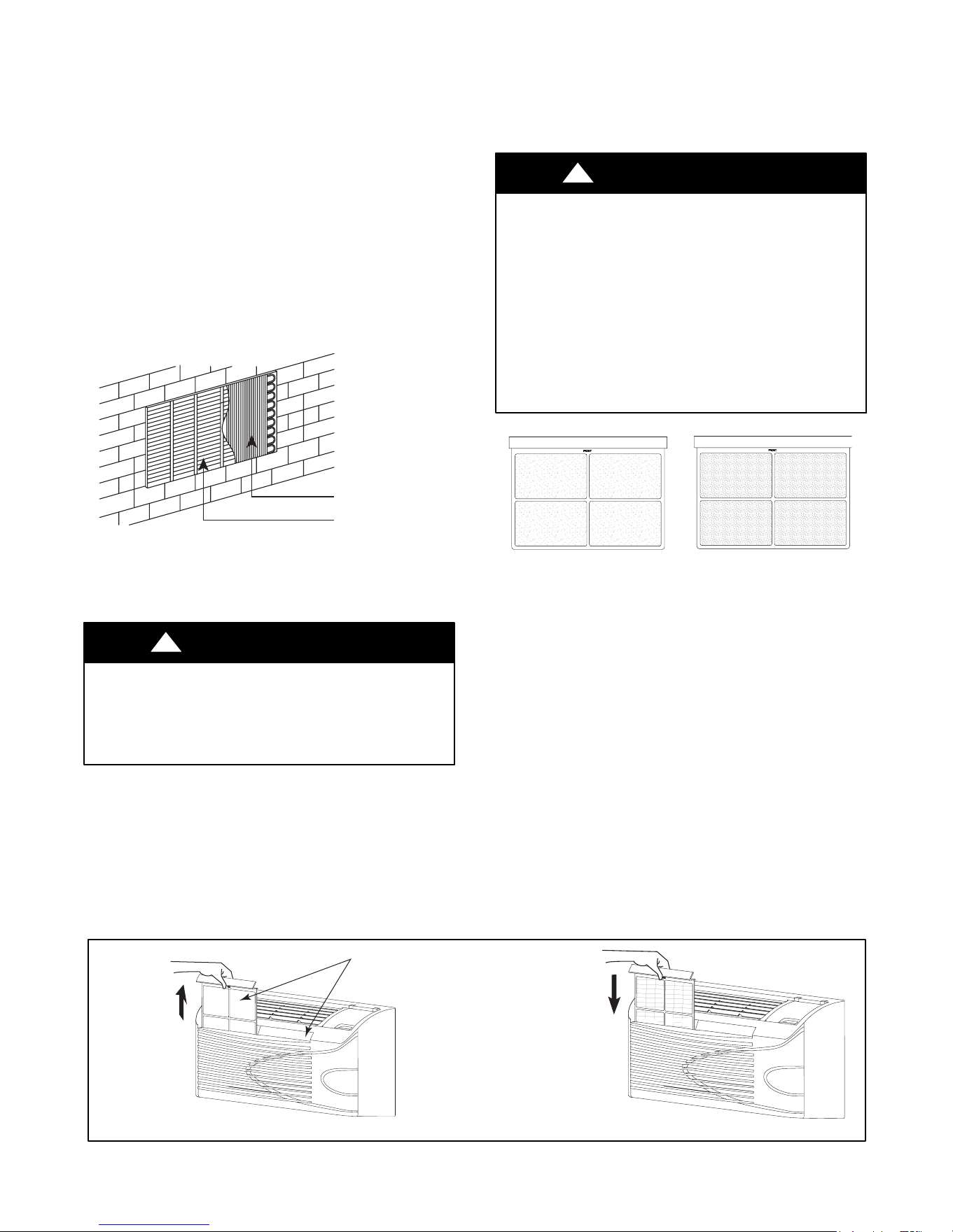
AIR FILTERS
IMPORTANT: TURN UNIT OFF BEFORE
CLEANING
UNIT DAMAGE HAZARD
Failure to follow this caution may result in equipment
damage or improper operation.
Do not operate unit without filters in place. If a filter
becomes torn or damaged, it should be replaced
immediately.
Operating without filters in place or with damaged filters
will allow dirt and dust to reach indoor coil and reduce
cooling, heating, airflow and efficiency of unit. Airflow
restriction may cause damage to unit.
CAUTION
!
Dirty filter-
Needs cleaning
Clogged filter -
Greatly reduces cooling,
heating and airflow.
A07078
Fig. 29 – Identifying Clogged Filter
The m ost important thing you can do to maintain unit
efficiency is to clean the filters at least every 30 days
(or sooner depending on application). Clogged filters
reduce cooling, heating and airflow.
Keeping filters clean will:
S Decrease cost of operation.
S Save energy.
S Prevent clogged indoor coil.
S R educe risk of premature component failure.
To Clean Air Filters:
S Vacuum off heavy soil.
S Run water through filters.
S Dry thoroughly before replacing.
2 Air filters
Pull up
Push down
A07080A07079
Removing Air Filter Replacing Air Filter
Fig. 30 – Removing and Replacing Air Filter
Downloaded from www.ManualsFile.com manuals search engine

18
PREVENTATI VE MAINTENANCE
Preventative maintenance is essential to proper unit operation, efficiency and longevity.
To ensure equipment operates properly, it must be properly maintained. Equipment operation should be checked
and verified several times during each year. Durin g regul ar unit in s pect i o n and m ai n t enan ce, fol l o w t h e
guidelines below:
S C l ean both sides of outdoor coil. (Never use high pressure spray on coils.)
S Clean basepan and outdoor vent filter.
S C lean outdoor orifice and fan.
S C l ean indoor coil. (Never use high pressure spray on coils.)
S Clean indoor fan, wire screen and front panel.
S Clean or install new indoor --air inlet filter(s).
S Clean wall sleeve and outdoor grille.
S Inspect cord and receptacle.
S Secure electrical connections.
S Ensure front panel is properly mounted and not damaged.
S Ensure wall sleeve is installed properly.
S Ensure heat and cool cycles operate properly.
Downloaded from www.ManualsFile.com manuals search engine

19
TROUBLESHOOTING
POSSIBLE CAUSES SOLUTIONS
UNIT DOES NOT START
• Unit may have become unplugged
• Fuse may have blown
• Circuit breaker may have been tripped
S Unit may be off or in wall thermostat mode.
Check section on dipswitch settings to verify
dipswitches are set properly.
• Unit may be in a protection or diagnostic failure
mode. See sect ion on Intelligent Self ---checking
Control.
• Check that plug is plugged securely in wall receptacle.
Note :Plug has a test/reset button on it. Make sure that the plug
has not tripped.
• Replace the fuse. See Note 1.
• Reset circuit breaker. See Note 1.
• Turn unit on (bottom right button on keypad).
Note: If the unit turns on, the LED will be green. If the unit is off,
the LED will be red. If there is no LED on, there is a problem
with power or damage to the control.
UNIT NOT COOLING/HEATING ROOM
S Unit air discharge sectio n is blocked
S Temperature setting is not high or low enough
Note: Setpoint limits may not allow the unit to heat
or cool the room to the temperature desired.
Check section on dipswitch settings.
S Unit air filters are dirty.
S Room is excessively hot or cold when unit is started.
S Vent door left open
S Unit may be in a protection or diagnostic failure
mode. Check section on Intelligent Self ---checking
Control.
S Compressor is in time delay. There is a protective
time delay (approx. 3 minutes) on starting the
compressor after a power outage (or restarting
after it has been turned off), to prevent tripping of
the compressor overload.
S Make sure that curtains, blinds or furniture are not restricting or
blocking unit airflow.
S Resettoalowerorhighertemperaturesetting.
S Remove and clean filters .
S Allow sufficient amount of time for unit to heat or cool the room.
Start heating or cooling early before outdoor temperature, cooking
heat or gatherings of people make room uncomfortable.
S Close vent door.
S Check dipswitch settings for desired comfort.
Wait approximately 3 minutes for compressor to start
DISPLAY HAS STRANGE
NUMBERS/CHARACTERS ON IT
• The unit may be in a diagnostic condition. Check Intelligent Self ---
checking Control sectio n to determine if unit has had a failure.
• Theunitmaybesetfor_C(insteadof_F), see the keypad
configuratio n section
UNIT MAKING NOISES • Clicking, gurgling and whooshing noises are normal during
operation of unit.
WATER DRIPPING OUTSIDE • If a drain kit has not been installed, condensatio n runoff during
very hot and humid weather is normal. See Note 2. If a drain kit has
been installed and is connected to a drain system, check gaskets
and fittings around drain for leaks and plugs.
WATER DRIPPING INSIDE
• Wall sleeve is not installed level • Wall sleeve must be installed level for proper drainage of
condensation. Check that installation is level and make any
necessary adjustments.
ICE OR FROST FORMS ON INDOOR COIL
• Low outdoo r temperature
• Dirty filters
• When outdoor temperature is approximately 55_Forbelow,frost
may form on the indoor coil when unit is in Cooling mode. Switch
unit to FAN operation until ice or frost melts.
• Remove and clean filters.
COMPRESSOR PROTECTION
• Power may have cycled, so compressor is in a
restart protection.
• Random Compressor restart --- Whenever the unit is plugged in,
or power has been restarted, a random compressor restart will
occur. After a power outage, the compressor will restart after
approximately 3 minutes.
• Compressor Protection --- To prevent short cycling of the
compressor, there is a random startup delay of 3 minutes and a
minimum compressor run time of 3 minutes.
NOTES:
1. If circuit breaker is tripped or fuse is blown more than once, contact a qualified electrician.
2. If unit is installed where condensation drainage could drip in an undesirable location, an accessory drain kit should be installed and connected to drain
system.
Downloaded from www.ManualsFile.com manuals search engine


23
Carrier
Packaged Terminal
Air Conditioner Warranty
FULL ONE-YEAR WARRANTY —
During the first year after purchase, CARRIER
will, through its authorized independent servicing dealers or service stations*, and
free of charge to the user or subsequent users, repair or replace any parts which
are defective in material or workmanship. The replacement part can be a new or
remanufactured part as provided at CARRIERÕS sole option.
FULL EXTENDED FOUR-YEAR WARRANTY ON SEALED REFRIGERATION
SYSTEM ONLY —
During the second through fifth years after date of original pur-
chase, CARRIER will, through its authorized servicing dealers and service stations*
and free of charge to the end user or subsequent users, repair or replace the
compressor, condenser, evaporator or connecting tubing if defective in material or
workmanship. This includes system refrigeration charge. The replacement part can
be new or a remanufactured part as provided at CARRIERÕS sole option.
LIMITED EXTENDED FOUR-YEAR WARRANTY ON NON-SEALED REFRIGER-
ATION SYSTEM ONLY —
During the second through fifth years after date of origi-
nal purchase, Carrier will, through its authorized servicing dealers and service
stations and free of charge to the end user or subsequent users, repair or replace
any non-sealed system part (motor, solenoid, thermistor, thermostat, relays, switch,
capacitor, overload, drain valve, bulb heater, fan, stator) if defective in material or
workmanship. The replacement part can be new or a remanufactured part at
CARRIERÕS sole option. THIS LIMITED WARRANTY DOES NOT INCLUDE
LABOR, user is responsible for labor, including cost of diagnosis of problem,
removal and transportation of the air conditioner to and from the service center, and
reinstallation charges necessary to accomplish repair.
LIMITATION OF WARRANTIES —
ALL IMPLIED WARRANTIES (INCLUDING
IMPLIED WARRANTIES OF MERCHANTABILITY) ARE HEREBY LIMITED IN
DURATION TO THE PERIOD FOR WHICH EACH LIMITED WARRANTY IS GIVEN
AND APPLIES. SOME STATES DO NOT ALLOW LIMITATIONS ON HOW LONG
AN IMPLIED WARRANTY LASTS, SO THE ABOVE LIMITATION MAY NOT APPLY
TO YOU. THE EXPRESSED WARRANTIES MADE IN THIS WARRANTY ARE
EXCLUSIVE AND MAY NOT BE ALTERED, ENLARGED, OR CHANGED BY ANY
DISTRIBUTOR, DEALER, OR OTHER PERSON WHATSOEVER.
ALL WORK UNDER THE TERMS OF THIS WARRANTY SHALL BE PERFORMED
DURING NORMAL WORKING HOURS. ALL REPLACEMENT PARTS, WHETHER
NEW OR REMANUFACTURED, ASSUME AS THEIR WARRANTY PERIOD ONLY
THE REMAINING TIME PERIOD OF THIS WARRANTY.
CARRIER WILL NOT BE RESPONSIBLE FOR:
1.
CLEANING REQUIRED PRIOR TO WARRANTY REPAIR.
2. Standard maintenance, cleaning or damage resulting from failure to perform
normal maintenance as outlined in the ownerÕs manual.
3. Instruction on methods of control and use of air conditioning unit after initial
installation.
4. Damage or repairs needed as a consequence of faulty installation or applica-
tion. This is the responsibility of the installer.
5. Failure to start due to voltage conditions, blown fuses, open circuit breakers
or any other damages due to the inadequacy or interruption of electrical
services.
6. Damage or repairs needed as a consequence of any misapplication, abuse,
unauthorized alteration, improper servicing or operation.
7. Damage as a result of floods, winds, fires, lightning, accidents, corrosive
environment, or other conditions beyond the control of CARRIER.
EXCEPTION TO CORROSIVE ENVIRONMENT IN ABOVE PARAGRAPH Ñ
Packaged terminal units (52 Series) built with corrosion protection are exempt
from the exclusion Ñ ÒCorrosive Environment.Ó The unit model number is
identified on the nameplate with a CP suffix.
8. Reimbursement for replacement parts or repair services which are not sup-
plied or designated by CARRIER and which are specifically covered under
this warranty.
9. CARRIER products installed outside the continental U.S.A., Alaska, Hawaii
and Canada.
10. Shipping damage or damage as a result of transporting the unit. This is the
responsibility of the selling dealer or the authorized Room Air Conditioner
service station.
11. ANY SPECIAL, INDIRECT OR CONSEQUENTIAL PROPERTY OR COM-
MERCIAL DAMAGE OF ANY NATURE WHATSOEVER. Some states do not
allow the exclusion or limitation of incidental or consequential damages, so
the above limitation or exclusion may not apply to you.
12. Warranty coverage of accessory items (wall thermostats, wall sleeves, etc.).
NOTE: Service and Maintenance items excluded in this warranty may be covered by
a separate service agreement through the seller at time of purchase.
*Authorized independent dealers or service stations are registered with Carrier Air Conditioning through its distributor organization.
This warranty gives you specific legal rights, and you may also have other rights which vary from state to state.
Catalog No. 530-122 (Rev. 3/02)
Downloaded from www.ManualsFile.com manuals search engine
24
Copyright 2007 Carrier Corp. S 7310 W. Morris St. S Indianapolis, IN 46231
Manufacturer reserves the right to change, at any time, specifications and designs without notice and without obligations.
Catalog No.52M---1SI
Replaces: NEW
Printed in U.S.A. Edition Date: 03/07
Downloaded from www.ManualsFile.com manuals search engine