Loading ...
Loading ...
Loading ...
9
Check capacitor (7) with an Ohm meter by grounding the
capacitor by placing a screwdriver across both terminals
and then removing the screwdriver. Connect Ohm meter
(set on high scale) to terminals, if needle moves to infi nity
( ∞ ) then drifts back, the capacitor is good. If needle does
not move or moves to infi nity ( ∞ ) and does not drift back,
replace capacitor (7).
Bearings - Disassemble motor as per section F-3.1.
Remove snap ring (6) with snap ring pliers and pull motor
(1) and lower bearing (4) straight off of seal plate (2).
Inspect all parts for signs of wear and replace as needed.
CAUTION! Handle seal parts with extreme
care. do not scratch or mar lapped surfaces.
F-3.2) Replacing Bearing:
When replacing bearing, be careful to not damage the
rotor or shaft threads. Press the old bearing off the
shaft with an arbor press or gear puller. Clean the shaft
thoroughly. Apply adhesive compound to shaft and press
new bearing on, pushing only on the inner race, until it
seats against shoulder of shaft (see fi g.8).
IMPORTANT! - All parts must be clean before
reassembly.
F-3.3) Reassembly:
Make sure shaft seal (3) is clean and in proper position as
per section F-4.2 before reassembling rotor and bearing.
Slide lower bearing and rotor shaft squarely into the seal
plate (2) until bearing seats on the bottom. Insert snap
ring (6) into seal plate with fl at edge against outer race of
bearing. Place motor stator squarely onto seal plate (2)
and tighten motor screws. Install o-ring (13) onto seal plate
(2).
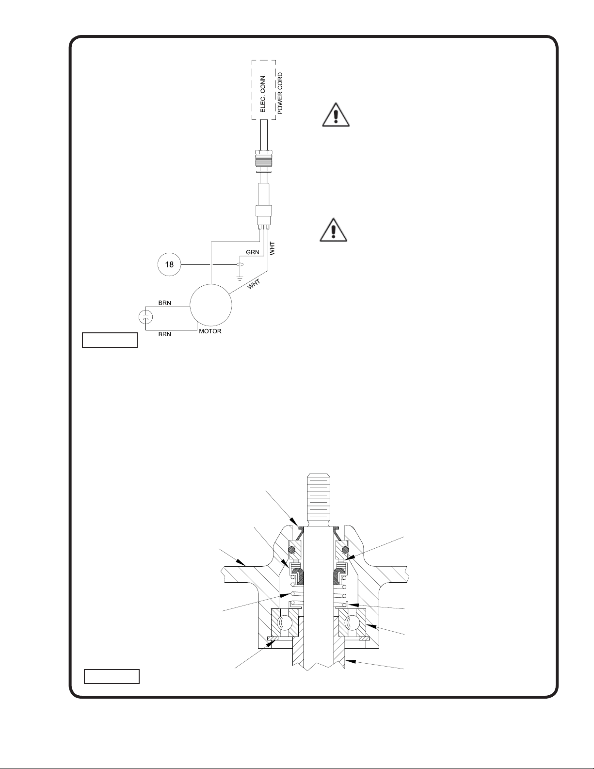
Slip motor wires through opening in motor housing (14)
see Figure 5. Connect motor wires to cord set as per
Figure 6. Place friction ring (9b) and gland nut (9a) into
motor housing (14) and tighten gland nut to 17.5 ft. lbs.
Place motor housing (14) squarely onto seal plate (2).
Tighten socket head screws (15) into motor housing. Refi ll
with cooling oil as per paragraph F-1.3.
Exclusion Seal
Bearing (4)
Seal Plate
Spring (3b)
Retaining Ring (6)
Stationary (3d)
Polished Mating Surface
Rotating Member (3c)
Sleeve (27)
MOTOR END
(Inboard End)
PUMP END
(Outboard End)
FIGURE 8
Retaining Ring (3a)
FIGURE 6
Loading ...
Loading ...
Loading ...