Loading ...
Loading ...
Loading ...
8
F-1.3 Replacing Oil in Motor Housing:
Drain all oil from motor housing and dispose of properly.
Refi ll with 58 ounces of new cooling oil as per Table 1. An
air space must remain in the top of the motor housing to
compensate for air expansion. Set unit upright and fi ll only
until oil level from top of pipe plug boss is 3” ± 1/4”.
When refi lling with oil after servicing the shaft seal (3), a
pressure test as per section F-1.4 should be done. If shaft
seal was not disturbed during service, then apply pipe
sealant and replace the pipe plug (24).
WARNING ! - DO NOT overfi ll oil. Overfi lling of
motor housing with oil can create excessive
and dangerous hydraulic pressure which
can destroy the pump and create a hazard.
Overfi lling oil voids warranty.
TABLE 1 - COOLING OIL - Dielectric
SUPPLIER GRADE
BP Enerpar SE100
Conoco Pale Paraffi n 22
Mobile D.T.E. Oil Light
G & G Oil Circulating 22
Imperial Oil Voltesso-35
Shell Canada Transformer-10
Texaco Diala-Oil-AX
Woco Premium 100
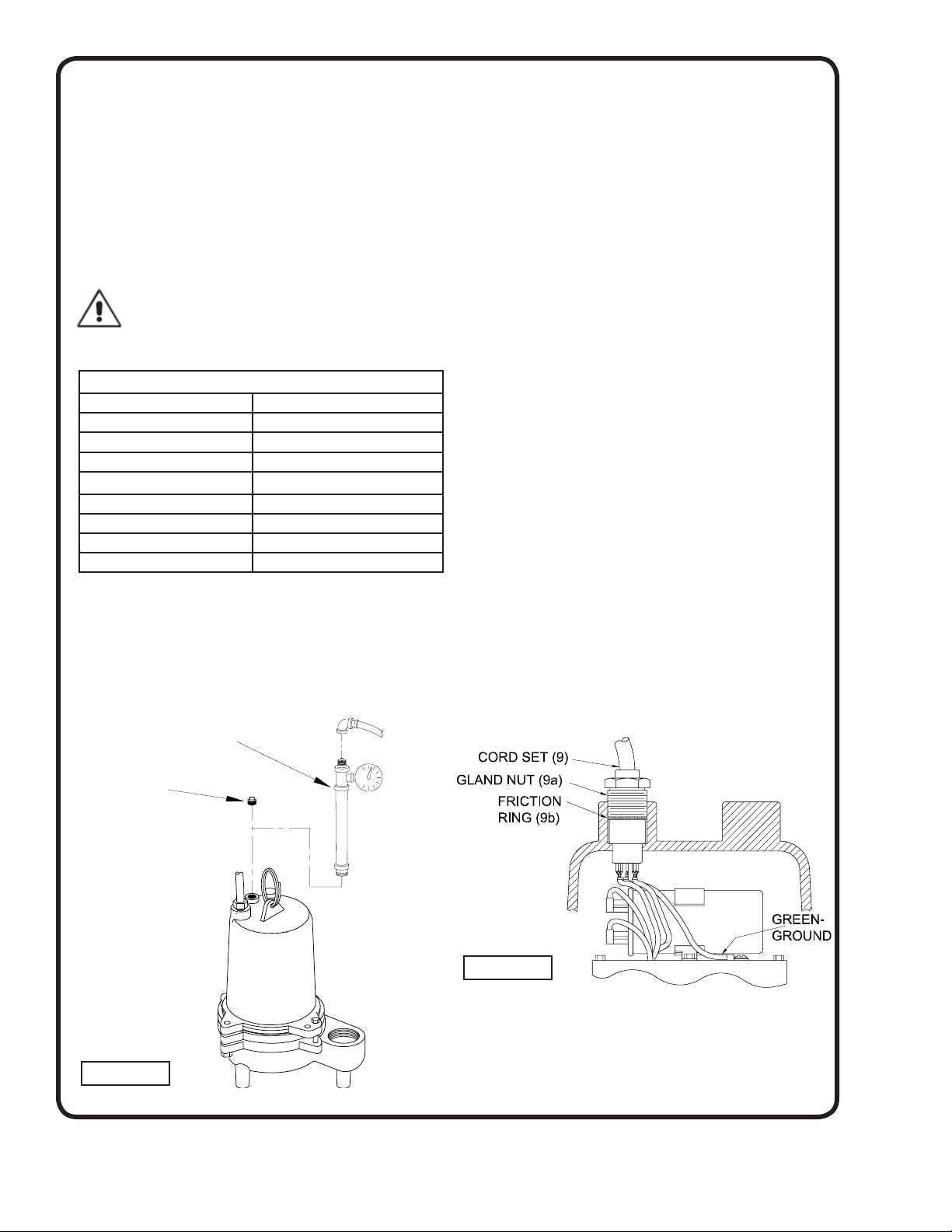
F-1.4) Pressure Test:
Before checking the pump for leaks around the shaft
seal, square ring, and cord inlet, the oil level should be
full as described in section F1.3. Apply pipe sealant to the
pressure gauge assembly and tighten into fi ll plug hole
(see Figure 4). Pressurize motor housing to 10 P.S.I.
Use a soap solution around the sealed areas and inspect
joints for “air bubbles”. If, after fi ve minutes, the pressure
is still holding constant, and no “bubbles” are observed,
slowly bleed the pressure and remove the gauge
assembly. Replace the pipe plug using a sealant. If the
pressure does not hold, then the leak must be located.
F-2) Impeller and Volute Service:
F-2.1) Disassembly and Inspection:
To clean out body (20), or to replace impeller (17),
disconnect power, remove hex bolts (21), and vertically lift
motor and seal assembly from body (20). Clean out body
if necessary . Clean and examine impeller (17) for pitting
or wear and replace if required. Inspect gasket (19) and
replace if cut or damaged. The impeller (17) is threaded
onto the shaft and to remove, unscrew impeller, holding
shaft with a large screwdriver. Remove exclusion seal (16)
and replace if needed.
F-2.2) Reassembly:
Before installing impeller (17), inspect threads on shaft
and impeller to assure that they are clean. Place exclu-
sion seal on shaft with the thin lip toward the motor (see
section F-4.3). Apply a thread-locking compound to shaft
threads and screw impeller onto shaft and tighten. Rotate
impeller to check for binding. Position gasket (19) on body
and install impeller and motor housing on pump body.
Apply thread locking compound to each cap screw (21),
thread into body, and torque to 11 ft. lbs. Check for free
rotation of impeller.
F-3) Motor, Bearing and Cable Service
F-3.1) Disassembly and Inspection:
Motor - To examine or replace the motor (1) or bearing
(4), remove body and impeller as per section F-2.1. Drain
oil from motor housing as per section F-1.2. Remove
gland nut (9a) and friction ring (9b) from motor housing
(14). Pull cord through opening and disconnect the motor
wires from the terminals on cable (9), see Figure 5.
Remove socket head screws (15) and lift motor housing
(14) from seal plate (2). Remove o-ring (13) and inspect
for breaks. Loosen motor screws and pull motor (1)
straight up and off seal plate (2). Inspect all parts for signs
of wear and check motor resistance values.
Í 10 PSI
AIR
Pressure Gauge Assembly
(See Parts List)
Remove Pipe
Plug
FIGURE 4
FIGURE 5
Loading ...
Loading ...
Loading ...