Loading ...
Loading ...
Loading ...
6
General Comments:
1) Never work in the sump with the power on.
2) Level controls are factory set for a pumping differential
of 9 inches. If that is the cycle desired, simply circle
the discharge pipe with the pipe mounting strap, feed
the end through the worm drive, and tighten with a
screwdriver. Be certain that the level control cannot
hang up or foul in its swing. Also, make certain the
pump impeller is still submerged when the level control
is in the “OFF” mode.
3) If a higher pump differential is needed, grip the cord
near the neck of the fl oat, then using the other hand,
exert a steady force on the lower edge of the cable
clamp. The cable clamp should slide up to the new
pivot point. Attach the level control to the discharge
hose in the manner described above.
4) Plug the level control plug into the GFI receptacle,
then plug the pump into the piggyback plug. One cycle
of operation should be observed, so that any potential
problems can be corrected.
5) It is recommended that the fl oat should be set to
insure that the sump well liquid level never drops
below the top of the motor housing or a minimum level
of 3 inches on BP Series and 6 inches on SE Series
above the pump bottom.
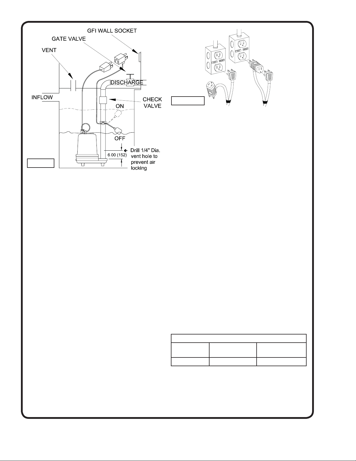
6.) Figure 3 shows a typical connection for pumps with the
wide angle fl oat and piggy-back plug, for manual and
automatic operations.
Automatic - Plug fl oat cord into GFI outlet, then plug pump
cord into fl oat cord.
Manual - Plug pump cord directly into GFI outlet.
C-4) Electrical Connections:
C-4.1) Power Cable:
The cord assembly mounted to the pump must not be
modifi ed in any way except for shortening to a specifi c
application. Any splice between the pump and the control
panel must be made in accordance with the electric codes.
It is recommended that a junction box, if used, be mounted
outside the sump or be of at least NEMA 4 (EEMAC-4)
construction if located within the wet well. Do not use the
power cable to lift pump. NOTE: THE WHITE WIRE IS
NOT A NEUTRAL OR GROUND LEAD, BUT A POWER
CARRYING CONDUCTOR.
C-4.2) Overload Protection:
Single Phase - The type of in-winding overload protector
used is referred to as an inherent overheating protector
and operates on the combined effect of temperature and
current. This means that the overload protector will trip out
and shut the pump off if the windings become too hot, or
the load current passing through them becomes too high.
It will then automatically reset and start the pump up
after the motor cools to a safe temperature. In the event
of an overload, the source of this condition should be
determined and rectifi ed immediately. DO NOT LET THE
PUMP CYCLE OR RUN IF AN OVERLOAD CONDITION
OCCURS !
If current through the temperature sensor exceeds the
values listed, an intermediate control circuit relay must
be used to reduce the current or the sensor will not work
properly.
TEMPERATURE SENSOR ELECTRICAL RATINGS
Volts Continuous
Amperes
Inrush
Amperes
110-120 3.00 30.0
C-4.3) Wire Size:
Consult a qualifi ed electrician for proper wire size. See
table for electrical information.
FIGURE 3
Manual
Automatic
FIGURE 2
Loading ...
Loading ...
Loading ...