Loading ...
Loading ...
Loading ...
Maintenance
Battery Charging
Service interval: As Required
WARNING
Keep open flames and sparks away from the
battery; the gasses coming from it are highly
explosive. Ventilate the battery well during
charging.
A dead battery or one too weak to start the engine may
be the result of a defect in the charging system or other
electrical component. If there is any doubt about the
cause of the problem, see your dealer. If you need to
replace the battery, follow the steps under "Battery
Maintenance" in the MAINTENANCE section.
To charge the battery, follow the instructions provided by
the battery charger manufacturer as well as all warnings
included in the safety rules sections of this book. Charge
the battery until fully charged. Do not charge at a rate
higher than 10 amps.
5. Check the windows for an equal amount of tension
when the gauge is inserted and removed, and make
any necessary adjustments by tightening or loosen-
ing the adjustment nuts.
NOTE: The actual air gap between the rotor and arma-
ture may vary even after performing the adjustment pro-
cedure. This is due to dimensional variations on compo-
nent parts, and is an acceptable condition.
6. Check the mower blade stopping time. The mower
blades and mower drive belt should come to a com-
plete stop within five seconds after the electric PTO
switch is turned off.
, Perform the "Blade Brake Check" found in the MAIN-
TENANCE section. Mower blades and mower drive
belt should come to a complete stop within five sec-
onds after electric PTO switch is turned off.
Brake Adjustment
This unit does not have a manually adjustable brake. If
brake does not function properly see your dealer.
PTO Clutch Adjustment
WARNING
To avoid serious injury, perform adjustments only
with engine stopped, key removed and tractor on
level ground.
Service Internal: Check the PTO clutch adjustment after
every 250 hours of operation. Also perform the following
procedure if the clutch is slipping or will not engage, or if
a new clutch has been installed.
1. Remove key from ignition switch and disconnect
spark plug wires to prevent the possibility of acciden-
tal starting while the PTO is being adjusted.
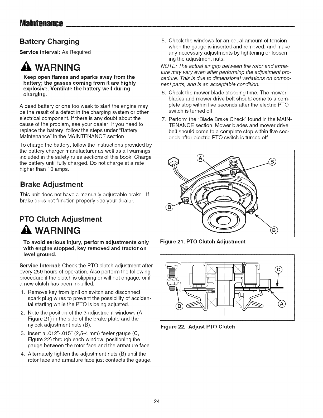
2. Note the position of the 3 adjustment windows (A,
Figure 21) in the side of the brake plate and the
nylock adjustment nuts (B).
3. Insert a .012"-.015" (2,5-4 mm) feeler gauge (C,
Figure 22) through each window, positioning the
gauge between the rotor face and the armature face.
4. Alternately tighten the adjustment nuts (B) until the
rotor face and armature face just contacts the gauge.
Figure 21. PTO Clutch Adjustment
I
Figure 22. Adjust PTO Clutch
24
Loading ...
Loading ...
Loading ...