02489
587785901 12.21.15 BY Printed in U.S.A.
Model No.
944.364152
CAUTION:
Read and follow all
Safety Rules and In struc tions
before operating this equipment
Owner’s Manual
ROTARY LAWN MOWER
160cc Honda Engine
21" Multi-Cut
Sears Canada, Inc., Toronto, Ontario M5B 2B8
2
Safety Rules .......................................... 2-3
Warranty - Lawn Mower ........................ 4-5
Product Spec i fi ca tions ........................... 5
Assembly/Pre-Operation ....................... 6-7
Operation ............................................ 8-11
Maintenance Schedule .......................... 12
Maintenance ...................................... 12-15
Service and Adjustments .................. 15-16
Storage .............................................. 16-17
Troubleshooting ................................ 18-19
Repair Parts ....................................... 20-27
Warranty - Honda Motor ................... 28-29
Sears Service ...........................Back Cover
TABLE OF CONTENTS
SAFETY RULES
IMPORTANT: This cutting machine is
capable of amputating hands and feet and
throwing objects. Failure to observe the
following safety instructions could result in
serious injury or death.
Look for this symbol to point out im por-
tant safety precautions. It means
CAU TION!!! BECOME ALERT!!!
YOUR SAFE TY IS INVOLVED.
WARNING: In order to prevent ac ci-
den tal starting when setting up, trans port-
ing, ad just ing or making repairs, always
dis con nect spark plug wire and place wire
where it can not come in contact with plug.
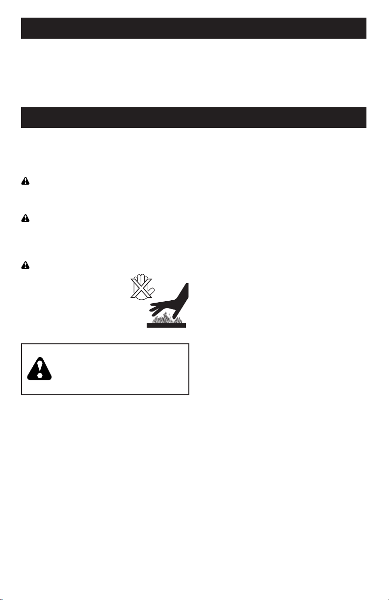
CAUTION: Muffler and other engine
parts become extremely
hot during operation and
remain hot after engine
has stopped. To avoid
severe burns on contact,
stay away from these areas.
I. CHILDREN
WARNING: CHILDREN CAN
BE SERIOUSLY INJURED OR
KILLED BY THIS EQUIPMENT.
Carefully read and follow all of
the safety instructions below.
The American Academy of Pediatrics
recommends that children be a minimum
of 12 year of age before operating a
pedestrian controlled lawn mower and a
minimum of 16 years of age before operat-
ing a riding lawn mower.
Tragic accidents can occur if the op er a tor is
not alert to the presence of children. Children
are often attracted to the ma chine and the
mowing activity. Never assume that children
will remain where you last saw them.
• Keep children out of the mowing area
and under the watchful care of a re-
spon si ble adult other than the operator.
• Be alert and turn machine off if chil dren
enter the area.
• Before and while walking back wards, look
behind and down for small chil dren.
• Never allow children to operate the
machine.
II. GENERAL OPERATION
• Read, understand, and follow all
in struc tions on the machine and in the
manual(s) before starting. Be thor ough ly
familiar with the controls and the proper
use of the machine before starting.
• Do not put hands or feet near or under
rotating parts. Keep clear of the dis-
charge opening at all times.
• Only allow responsible individuals, who
are familiar with the in struc tions, to
operate the machine.
• Clear the area of objects such as rocks,
toys, wire, bones, sticks, etc., which
could be picked up and thrown by
blade. Stay behind the handle when the
engine (motor) is running.
• Be sure the area is clear of other people
before mowing. Stop ma chine if anyone
enters the area.
• Do not operate machine bare footed or
while wearing sandals. Al ways wear
substantial footwear with good ankle
support while mowing.
• Do not pull mower backwards unless
absolutely nec es sary. Always look down
and behind before and while moving
backwards.
• Never direct discharged material toward
anyone. Avoid discharging material
against a wall or obstruction. Material may
richochet back toward the operator. Stop
blade when crossing gravel surfaces.
• Do not operate the mower without
proper guards, plates, grass catcher or
oth er safety protective devices in place.
• See manufacturer’s instructions for
proper operation and installation of
accessories. Only use accessories ap-
proved by the manufacturer.
• Stop the blade(s) when crossing grav el
drives, walks, or roads.
• Never leave a running machine unattended.
• Stop the engine (motor) and wait until the
blade comes to a complete stop before
clean ing the machine, removing the grass
catcher, or unclogging the discharge
chute.
31
SERVICE NOTES

30
SERVICE NOTES
3
• Mow only in daylight or good artificial light.
• Do not operate the machine while under
the influence of alcohol or drugs.
• Never operate machine in wet grass.
Always be sure of your footing: keep a
firm hold on the handle; walk, never run.
• Disengage the drive system, if so equipped,
before starting the engine (motor).
• If the equipment should start to vi brate
abnormally, stop the engine (motor) and
check immediately for the cause. Vibra-
tion is generally a warning of trouble.
• Always wear eye protection when op er-
at ing machine.
• Use extra care when approaching blind
corners, shrubs, trees, or other objects
that may obscure vision.
• When loading or unloading this ma-
chine, do not exceed the maximum
recommended operation angle of 15°.
• Wear proper Personal Protective Equip-
ment (PPE) while operating this machine,
including (at a minimum) sturdy footwear,
eye protection, and hearing protection. Do
not mow in shorts or open toed footwear.
Always let someone know you are outside
mowing.
III. SLOPE OPERATION
Slopes are a major factor related to slip &
fall accidents, which can result in severe
injury. All slopes require extra caution. If
you feel uneasy on a slope, do not mow it.
DO:
• Mow across the face of slopes: nev er
up and down. Exercise extreme caution
when changing direction on slopes.
• Remove obstacles such as rocks, tree
limbs, etc.
• Watch for holes, ruts, bumps or hidden ob-
jects. Uneven terrain could cause a slip and
fall accident. Tall grass can hide obstacles.
DO NOT:
• Do not mow near drop-offs, ditches or
embankments. You could lose your foot-
ing or balance.
• Do not mow on wet grass or excessively
steep slopes. Poor footing could cause
a slip and fall accident.
IV. SAFE HANDLING OF GASOLINE
To avoid personal injury or property dam-
age, use extreme care in handling gaso-
line. Gasoline is extremely flammable and
the vapors are explosive.
• Extinguish all cigarettes, cigars, pipes
and other sources of ignition.
• Use only an approved container.
• Never remove gas cap or add fuel with
the engine running.
• Allow engine to cool before refueling.
• Never refuel the machine indoors.
• Never store the machine or fuel contain-
er where there is an open flame, spark
or pilot light such as a water heater or
on other appliances.
• Never fill containers inside a vehicle, on
a truck or trailer bed with a plastic liner.
Always place containers on the ground
away from your vehicle before filling.
• Remove gas-powered equipment from
the truck or trailer and refuel it on the
ground. If this is not possible, then
refuel such equipment with a portable
container, rather than from a gasoline
dispenser nozzle.
• Keep the nozzle in contact with the rim
of the fuel tank or container opening at
all times until fueling is complete. Do
not use a nozzle lock-open device.
• If fuel is spilled on clothing, change
clothing immediately.
• Never overfill fuel tank. Replace gas
cap and tighten securely.
V. GENERAL SERVICE
• Never run a machine inside a closed area.
• Never make adjustments or repairs with
the engine (motor) running. Dis con nect
the spark plug wire, and keep the wire
away from the plug to prevent ac ci den-
tal starting.
• Keep all nuts and bolts tight to be sure the
equipment is in safe working condition.
• Never tamper with safety devices.
Check their proper operation reg u lar ly.
Never do anything to interfere with the
intended function of a safety device or
reduce the protection provided by a
safety device.
• Keep machine free of grass, leaves, or
other debris build-up. Clean oil or fuel spill-
age. Allow machine to cool before storing.
• Stop and inspect the equipment if you
strike an object. Repair, if nec es sary,
before restarting.
• Never attempt to make wheel height
adjustments while the engine is running.
• Grass catcher components are sub ject
to wear, dam age, and de te ri o ra tion,
which could expose moving parts or
allow objects to be thrown. Frequently
check com po nents and replace with
man u fac tur er’s recommended parts,
when necessary.
• Mower blades are sharp and can cut.
Wrap the blade(s) or wear gloves, and
use extra caution when ser vic ing them.
• Do not change the engine governor set-
ting or overspeed the engine.
• Maintain or replace safety and instruc-
tion labels, as necessary.

4
WARRANTY
GENERAL: Craftsman products are warranted to be free from defects in materials
or workmanship for a specific time period as set-out below (the “Warranty Period”).
Warranties extend to the original purchaser of a Craftsman product only. Purchases
made through an online auction or through any website other than www.sears.ca are
excluded. The relevant Warranty Period commences on the original date of purchase.
Within this period, Sears Canada, Inc. will, at its sole option, repair or replace any
products or components which fail in normal use. Such repairs or replacement will be
made at no charge to the customer for parts or labor, provided that the customer shall be
responsible for any transportation cost.
EXCLUSIONS: This warranty does not cover failures due to normal wear, abuse, misuse,
neglect (including but not limited to the use of stale fuel, dirt, abrasives, moisture, rust,
corrosion, or any adverse reaction due to improper storage or use habits), improper
maintenance or failure to follow maintenance guidelines and/or instructions, failure to
operate the product in accordance with the owner’s manual or any additional instructions
or information provided at the time of purchase or in subsequent communications with
the original purchaser, accident or unauthorized alterations or repairs made or attempted
by others. Also excluded from warranty coverage – except as provided below - are
the following: maintenance, adjustments, components subject to wear including but
not limited to: cosmetic components, belts, blades, blade adapters, bulbs, tires, filters,
guide bars, lubricants, seats, grips, recoil assy’s, saw chains and bars, trimmer lines and
spools, spark plugs, starter ropers and tines, and discoloration resulting from ultraviolet
light. Any product missing the model and/or serial number identification label will be
disqualified from coverage under this warranty.
REPAIRS: Repairs have a 90 day warranty. If the defective product is still within the
Warranty Period, then the new warranty is 90 days from the date of repair or to the end of
the original Warranty Period, whichever period is longer.
DISCLAIMERS: THE WARRANTIES AND REMEDIES CONTAINED HEREIN ARE
EXCLUSIVE AND IN LIEU OF ALL OTHER WARRANTIES, WHETHER ORAL OR
WRITTEN (OTHER THAN AS STATED HEREIN), AND WHETHER EXPRESS, IMPLIED
OR STATUTORY, INCLUDING BUT NOT LIMITED TO ANY. THIS WARRANTY GIVES YOU
SPECIFIC LEGAL RIGHTS, WHICH MAY VARY FROM PROVINCE TO PROVINCE.
IN NO EVENT SHALL SEARS BE LIABLE FOR ANY INCIDENTAL, SPECIAL, INDIRECT
OR CONSEQUENTIAL DAMAGES, WHETHER RESULTING FROM THE USE, MISUSE
OR INABILITY TO USE THE PRODUCT OR FROM DEFECTS IN THE PRODUCT. THE
EXCLUSIONS IN THIS PARAGRAPH SHALL NOT APPLY IN JURISDICATIONS WHERE
APPLICABLE LAW DOES NOT ALLOW FOR THE EXCLUSION OF INCIDENTAL OR
CONSEQUENTIAL DAMAGES. IN SUCH JURISDICTIONS, THIS PARAGRAPH SHALL
NOT APPLY, BUT THE REMAINING PROVISIONS OF THIS DOCUMENT SHALL REMAIN
VALID.
Sears retains the exclusive right to repair or replace the product or offer a full refund of
the purchase price at its sole discretion. SUCH REMEDY SHALL BE YOUR SOLE AND
EXCLUSIVE REMEDY FOR ANY BREACH OF WARRANTY.
CUSTOMER RESPONSIBILITIES: In additional to complying with all suggested
maintenance guidelines and instructions, customers’ obligations shall include but shall
not be limited to: operating the product in accordance with the owner’s manual or any
additional instructions or information provided at the time of purchase or in subsequent
communications to the purchaser from time to time, exhibit reasonable care in the use,
operation, maintenance, general upkeep and storage of the product. Failure to comply
with these requirements will void any applicable warranty.
29
American Honda Motor Co., Inc.
Power Equipment Customer Relations
4900 Marconi Drive
Alpharetta, Georgia 30005-8847
Telephone: (888) 888-3139
Email: [email protected]
or
Honda Canada Inc.
Power Equipment Customer Relations
Visit www.honda.ca
for contact information.
Telephone: (888) 946-6329
Only Honda approved replacement parts may be used in the performance of any warranty repairs
and must be provided without charge to the owner. The use of replacement parts not equivalent
to the original parts may impair the effectiveness of your engine emission control system. If such
a replacement part is used in the repair or maintenance of your engine, and an authorized Honda
dealer determines it is defective or causes a failure of a warranted part, your claim for repair of
your engine may be denied. If the part in question is not related to the reason your engine requires
repair, your claim will not be denied.
TO OBTAIN WARRANTY SERVICE:
You must, at your own expense, take your Honda Power Equipment engine or the product on
which it is installed, along with your sales registration card or other proof of original purchase date,
to any Honda Power Equipment dealer who is authorized by Honda to sell and service that Honda
product during his normal business hours. Claims for repair or adjustment found to be caused
solely by defects in material or workmanship will not be denied because the engine was not prop-
erly maintained and used.
If you are unable to obtain emission warranty service or are dissatisfied with the warranty service
you received, contact the owner of the dealership involved. Normally this should resolve your
problem. However, if you require further assistance, contact the Honda office in your region:
American Honda Motor Co., Inc. / Honda Canada Inc. 10/2009 00X51-ZG0-6110 PWL50975-M
EXCLUSIONS:
Failures other than those resulting from defects in material or workmanship are not covered by this
warranty. This warranty does not extend to emission control systems or parts that are affected or dam-
aged by owner abuse, neglect, improper maintenance, misuse, misfueling, improper storage, colli-
sion, the incorporation of, or use of, unsuitable attachments, or the unauthorized alteration of any part.
This warranty does not cover replacement of expendable maintenance items made in connec-
tion with required maintenance service after the item’s first scheduled replacement as listed in the
maintenance section of the product owner’s manual, such as: spark plugs and filters.
Disclaimer of Consequential Damage and Limitation of Implied Warranties:
American Honda Motor Co., Inc. and Honda Canada Inc. disclaim any responsibility for inciden-
tal or consequential damages such as loss of time or the use of the power equipment, or any
commercial loss due to the failure of the equipment; and any implied warranties are limited to the
duration of this written warranty. This warranty is applicable only where the California, U.S. EPA, or
Environment Canada emission control system warranty regulation is in effect.
EMISSION CONTROL SYSTEM WARRANTY PARTS:
SYSTEMS PARTS
COVERED: DESCRIPTION:
Fuel Metering Carburetor Assembly (Includes Starting Enrichment System), Engine Temp-
erature Sensor, Engine Control Module, Fuel Regulator, Intake Manifold
Evaporative Fuel Tank, Fuel Cap, Fuel Hoses, Vapor Hoses, Carbon Canister, Canister
Mounting Brackets, Fuel Strainer, Fuel Cock, Fuel Pump, Fuel Hose Joint,
Canister Purge Hose Joint
Exhaust Catalyst, Exhaust Manifold
Air Induction Air Filter Housing, Air Filter Element*
Ignition Flywheel Magneto, Ignition Pulse Generator, Crankshaft Position Sensor, Power
Coil, Ignition Coil Assembly, Ignition Control Module, Spark Plug Cap, Spark Plug*
Crankcase Emission Control Crankcase Breather Tube, Oil Filler Cap
Misc. Items Tubing, Fittings, Seals, Gaskets & Clamps associated with these listed systems
Note: This list applies to parts supplied by Honda and does not cover parts supplied by the
equipment manufacturer. Please see the original equipment manufacturer’s emissions warranty for
non-Honda parts.
* Covered up to the first required replacement only.
See the Maintenance Schedule in the owner’s manual.

28
EMISSION CONTROL SYSTEM WARRANTY
Your new Honda Power Equipment engine complies with the U.S. EPA, Environment Canada, and
State of California emission regulations (models certified for sale in California only). American Hon-
da Motor Co., Inc. provides the emission warranty coverage for engines in the United States and
its territories. Honda Canada Inc. provides the emission warranty for engines in the 13 provinces
and territories of Canada. In the remainder of this Emission Control System Warranty, American
Honda Motor Company Inc. and Honda Canada Inc. will be referred to as Honda.
YOUR WARRANTY RIGHTS AND OBLIGATIONS:
California
The California Air Resources Board and Honda are pleased to explain the emission control system
warranty on your Honda Power Equipment engine. In California, new spark-ignited small off-road
equipment engines must be designed, built, and equipped to meet the State's stringent anti-smog
standards.
Other States, U.S. territories, and Canada
In other areas of the United States and in Canada, your engine must be designed, built, and
equipped to meet the U.S. EPA and Environment Canada emission standards for spark-ignited en-
gines at or below 19 kilowatts. Specific Honda products that do not meet the California emissions
regulations can be identified by a “Not for sale in California” decal.
All of the United States and Canada
Honda must warrant the emission control system on your power equipment engine for the period
of time listed below, provided there has been no abuse, neglect, or improper maintenance of your
power equipment engine. Where a warrantable condition exists, Honda will repair your power
equipment engine at no cost to you including diagnosis, parts, and labor.
Your emission control system may include such parts as the carburetor or fuel injection system,
the ignition system, and catalytic converter. Also included may be hoses, connectors, and other
emission-related assemblies (see next page for additional covered parts).
OWNER'S WARRANTY RESPONSIBILITY:
As the power equipment engine owner, you are responsible for the performance of the required
maintenance listed in your owner's manual. Honda recommends that you retain all receipts covering
maintenance on your power equipment engine, but Honda cannot deny warranty coverage solely
for the lack of receipts or for your failure to ensure the performance of all scheduled maintenance.
As the power equipment engine owner, you should however be aware Honda may deny you
warranty coverage if your power equipment engine or a part has failed due to abuse, neglect,
improper maintenance, or unapproved modifications.
You are responsible for presenting your power equipment engine to a Honda Power Equipment
dealer as soon as a problem exists. The emission related warranty repairs should be completed
in a reasonable amount of time, not to exceed 30 days. If you have any questions regarding your
emission warranty rights and responsibilities, you should contact the Honda office in your region:
WARRANTY COVERAGE:
Honda power equipment engines sold in the United States and Canada are covered by this war-
ranty for a period of two years from the date of delivery to the original retail purchaser or the length
of the Honda Distributor’s Limited Warranty, whichever is longer. This warranty is transferable to
each subsequent purchaser for the duration of the warranty period.
If any emission-related part on your engine is defective, the part will be repaired or replaced by
Honda without charge for diagnosis, parts, or labor. All defective parts replaced under this warran-
ty become the property of Honda. A list of warranted parts is on the reverse side of this warranty
statement. Normal maintenance items, such as spark plugs and filters, that are on the warranted
parts list are warranted up to their required replacement interval only.
Honda will also replace other engine components damaged by a failure of any warranted part dur-
ing the warranty period.
American Honda Motor Co., Inc.
Power Equipment Customer Relations
4900 Marconi Drive
Alpharetta, Georgia 30005-8847
Telephone: (888) 888-3139
Email: [email protected]
or
Honda Canada Inc.
Power Equipment Customer Relations
Visit www.honda.ca
for contact information.
Telephone: (888) 946-6329
American Honda Motor Co., Inc. / Honda Canada Inc. 10/2009 00X51-ZG0-6110 PWL50975-M
5
LIST OF APPLICABLE WARRANTY PERIODS: The following list contains the applicable
Warranty Period for your Craftsman product and is based on a combination of the type
of product or component and the intended and actual use of the product or component:
1. 90 DAYS: Craftsman products intended for use or actually used for commercial,
institutional, professional or income-producing purposes
2. 2 YEARS: Craftsman riding lawn mowers, yard and garden tractors, walk behind
mowers, tillers, brush cutters, snow blowers, handheld blowers, backpack blowers,
hedge trimmers and electrical products for noncommercial, nonprofessional, non-
institutional, or non-income-producing use, except for those components which are
part of engine systems manufactured by third party engine manufacturers for which
the purchase has received an separate warranty with product information supplied
at the time of purchase.
3. 1 YEAR: Craftsman power cutters, stump grinders, pole pruners, gas chain saws,
electric chain saws, trimmer attachments, baggers and pole saws for noncommercial,
nonprofessional, non-institutional, or non-income-producing use.
4. 90 DAYS: All defective batteries, which will be replaced during this 90-day Warranty
Period.
5. 60 DAYS: Additional Warranty Period of 60 days will apply to adjustments and worn
products or components BUT DOES NOT INCLUDE WEAR OR ADJUSTMENTS
for products used for commercial, institutional, professional or income-producing
purposes. Wear items include but are not limited to: belts, blades, tires, spark plugs,
air filters, chains, shear bolts, skid plates, scraper bars, drift cutters, ropes, tines,
collection bags and pulleys.
As the Warranty Period runs from the date of purchase and NOT from the date that a
product is delivered, opened, assembled or first used, plea se ensure during this time
period that your product or component has been assembled and tested for correction
operation regardless of when you intend to actually use it. Claims made after the
Warranty Period has expired will not be honored.
PROOF OF PURCHASE/DOCUMENTATION: Warranty coverage is conditioned upon
the original purchaser furnishing Sears Canada or its authorized third party service
provider if applicable, with the original sales receipt or other adequate written proof
of the original purchase date and identification of the product. In the event that the
original purchaser is unable to provide a company of the original sales receipt, Sears
Canada Inc. reserves the right to determine in its sole discretion what other written
proof of the original purchase date and identification of the product is acceptable.
WARRANTY
Serial Number:
Date of Purchase:
Gasoline Capacity / Type: 1 Quart/0,94 Liters (Unleaded Regular)
Oil Capacity: 0,58 Quart/0,55 Liter
Oil Type (API SG–SL): SAE 30 (above 0°C/32°F) or SAE 10W-30
Spark Plug (Gap: 0,03"/0,76 mm) NGK BPR5ES
Valve Clearance (± 0.04 mm): Intake: 0.015 mm; Exhaust: 0.020 mm
Blade Bolt Torque: 35–40 ft. lbs. (47–54 Nm)
• The model and serial numbers will be found on a decal on the rear of the lawn mower
housing. Record both serial number and date of purchase in space provided above.
PRODUCT SPECIFICATIONS
6
ASSEMBLY / PRE-OPERATION
Read these instructions and this manual
in its entirety before you attempt to as-
semble or operate your new lawn mower.
IMPORTANT: This lawn mower is
shipped WITHOUT OIL OR GASOLINE in
the engine.
Your new lawn mower has been as sem-
bled at the factory with the exception of
those parts left unassembled for shipping
purposes. All parts such as nuts, wash-
ers, bolts, etc., nec es sary to complete the
as sem bly have been placed in the parts
bag. To ensure safe and proper operation
of your lawn mower, all parts and hard-
ware you assemble must be tightened
securely. Use the correct tools as neces-
sary to ensure proper tightness.
TO REMOVE MOWER FROM
CAR TON
1. Remove loose parts included with
mower.
2. Cut down two end corners of carton
and lay end panel down flat.
3. Remove all packing materials except
padding between upper and lower
handle and padding holding operator
presence control bar to upper handle.
4. Roll mower out of carton and check
carton thor ough ly for additional loose
parts.
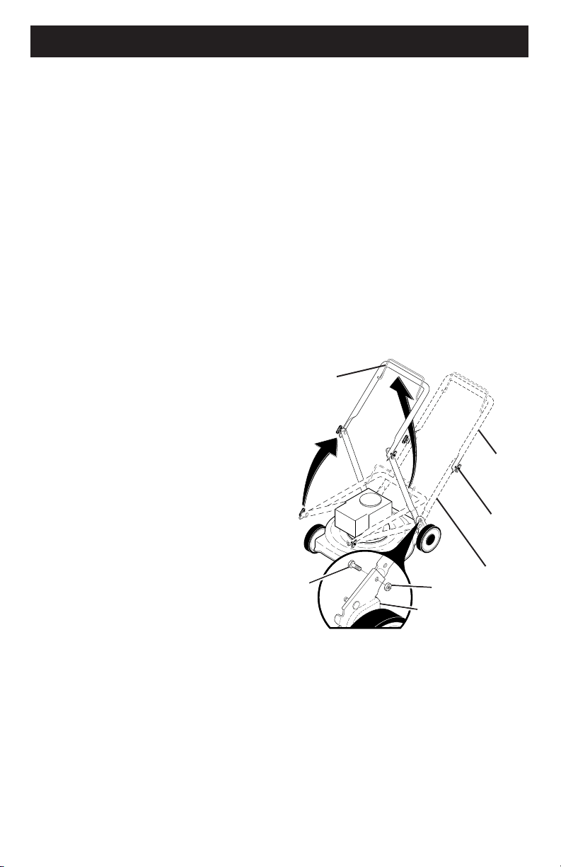
MOWING
POSITION
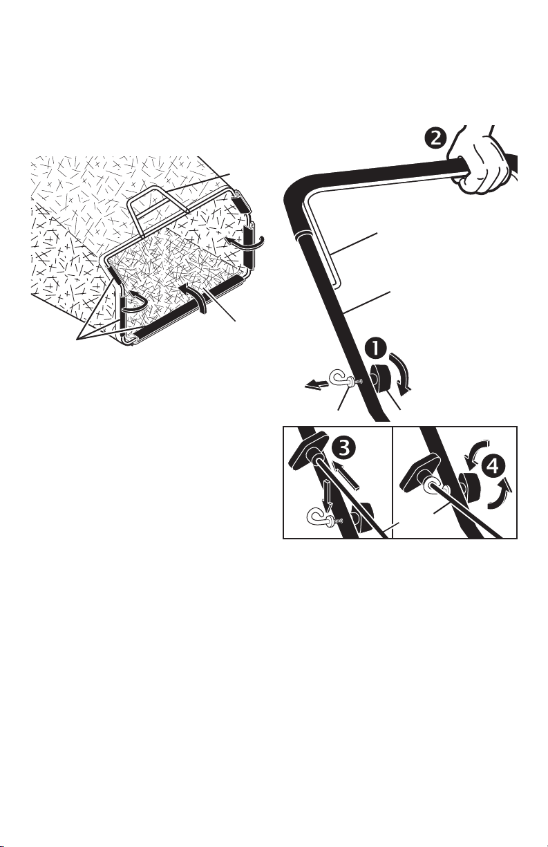
Lower handle
LIFT
UP
Operator
presence
control bar
Bolt
Nut
Bracket
Upper
handle
LIFT
UP
Handle
knob
HOW TO SET UP YOUR LAWN
MOW ER
TO UNFOLD HANDLE
IMPORTANT: Unfold handle carefully so
as not to pinch or damage con trol cables.
1. Raise handles until lower handle sec-
tion locks into place in mowing posi-
tion.
2. Insert bolt through handle and bracket
and secure with nut.
3. Remove protective padding, raise up-
per handle sec tion into place on lower
handle and tighten both handle knobs.
4. Remove handle padding holding
operator pres ence control bar to upper
handle.
Your lawn mower handle can be adjusted
for your mowing comfort. Refer to "AD-
JUST HANDLE" in the Service and Adjust-
ments section of this manual.
27
MODEL NUMBER GCV160-LAOS3B
HONDA 4-CYCLE ENGINE
CAMSHAFT PULLEY
KEY PART
NO. NO. DESCRIPTION
1 14320-ZL8-010 Pulley, Camshaft
2 14324-ZL8-000 Shaft, Cam Pulley
3 14400-Z0J-014 Belt, Timing
(84HU7 G-200)
6 14461-ZL8-000 Shaft, Rocker Arm
11 90112-333-000 Screw, Tappet Adjusting
12 90206-001-000 Nut, Tappet Adjusting
13 91301-ZM0-V31 O-Ring (6.8 x 1.9) (ARAI)
15 14431-Z0J-000 Rocker Arm, Intake Valve
16 14441-Z0J-000 Rocker Arm,
Exhaust Valve
OIL PAN
KEY PART
NO. NO. DESCRIPTION
1 11300-ZM0-811 Pan Assembly, Oil
2 15650-ZM0-801 Gauge Assembly,
Oil Level
4 15625-ZE6-000 Gasket, Oil Filler Cap
5 15631-ZM0-000 Extension, Oil Filler
6 15639-ZM0-000 Lock Washer, Extension
8 16508-ZM0-010 Shaft, Governor Holder
9 16510-ZM0-010 Governor Assembly
10 16511-ZL8-000 Weight, Governor
11 16512-ZM0-000 Holder, Governor Weight
12 16513-ZE1-000 Pin, Governor Weight
13 16531-ZE1-000 Slider, Governor
14 16541-ZM0-000 Shaft, Governor Arm
15 90014-952-000 Bolt, Flange (#6 x 14)
(CT200)
16 90121-952-000 Bolt, Flange (#6 x 25)
(CT200)
17 90451-ZE1-000 Washer, Thrust (6 mm)
18 90602-ZE1-000 Clip, Governor Holder
19 91202-ZL8-003 Oil Seal (28 x 41.25 x 6)
20 91356-MA6-005 O-Ring (14.8 x 2.4) (NOK)
21 94101-068000 Washer, Plain (6 mm)
22 94251-08000 Pin, Lock (8 mm)
23 94301-08200 Pin, Dowel (#8 x 20)
PISTON / CONNECTING ROD
KEY PART
NO. NO. DESCRIPTION
1 13101-Z2A-010 Piston
2 13111-ZE0-000 Pin, Piston
3 13200-Z0J-000 Connecting Rod Assem-
bly
4 90001-ZE1-000 Bolt, Connecting Rod
5 90551-ZE0-000 Clip, Piston Pin (13 mm)
6 13010-Z0L-014 Ring Set, Piston, Standard
(Teikoku)
LABELS
KEY PART
NO. NO. DESCRIPTION
9 87528-Z0L-V20 Mark, Choke Indication
20 87114-ZH7-821 Label, Warning
30 87101-Z8B-000 Mark, Emblem (GCV160)
31 87169-Z8E-000 Mark, Recoil Cover
32 87524-Z8B-000 Mark, Caution,
Fuel Petcock
CHOKE BASE
KEY PART
NO. NO. DESCRIPTION
2 16592-Z2D-800 Spring, Return
5 16614-Z2D-800 Spring, Choke Lever
8 16632-Z0L-801 Rod, Stop
9 90022-888-010 Bolt, Flange (#6 x 20)
(CT200)
14 16610-Z2D-801 Lever Assembly, Choke
16610-Z2D-802 Lever Assembly, Choke
26
MODEL NUMBER GCV160-LAOS3B
HONDA 4-CYCLE ENGINE
7
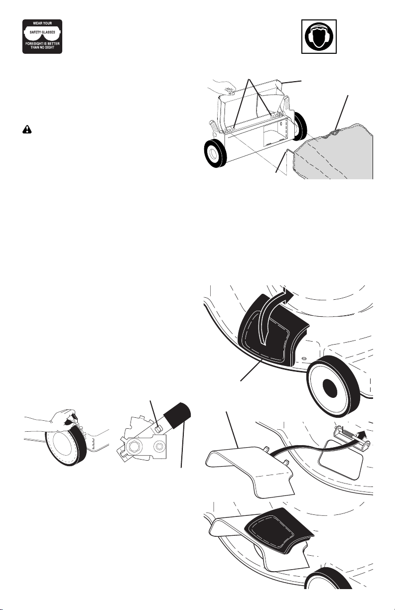
TO ASSEMBLE GRASS CATCH ER
1. Put grass catcher frame into grass bag
with rigid part of bag on the bottom.
Make sure the frame handle is outside
of the bag top.
2. Slip vinyl bindings over frame.
NOTE: If vinyl bindings are too stiff, hold
them in warm water for a few minutes. If
bag gets wet, let it dry before using.
TO INSTALL ATTACHMENTS
Your lawn mower was shipped ready to
be used as a mulcher. To convert to bag-
ging, see “TO CON VERT MOW ER” in the
Operation section of this man u al.
Frame
handle
Frame
opening
Vinyl
bindings
INSTALL STARTER ROPE
1. Loosen T-knob.
2. Hold control bar against upper handle.
3. Slowly pull engine starter rope out until
rope will slip into loop of rope guide.
4. Tighten T-knob.
Upper handle
Control bar
Engine
starter rope
Rope guide
T-Knob
8
IMPORTANT: This lawn mower is shipped
WITHOUT OIL OR GASOLINE in the engine.
NOTE: Gasoline containing up to 10% ethanol (E10) is acceptable for use in this machine.
The use of any gasoline exceeding 10% ethanol (E10) will void the product warranty.
OPERATION
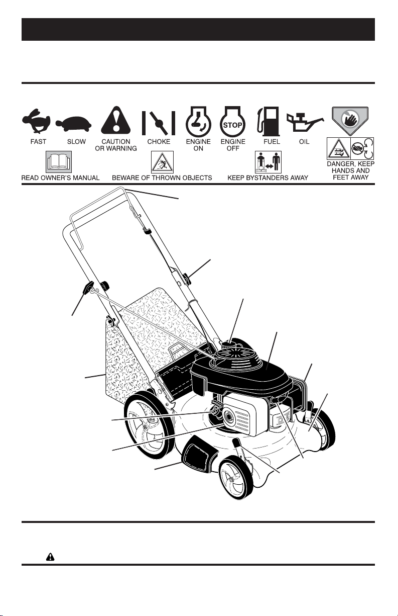
KNOW YOUR LAWN MOWER
READ THIS OWNER'S MANUAL AND ALL SAFETY RULES BEFORE OPERATING YOUR
LAWN MOWER. Compare the illustrations with your lawn mower to familiarize yourself with
the location of various controls and adjustments. Save this manual for future reference.
Starter
handle
Housing
Wheel adjuster
(on each wheel)
Handle knob
Grass
catcher
Engine oil plug
Operator presence control bar
Fuel valve lever
MEETS CPSC SAFETY REQUIREMENTS
Sears rotary walk-behind power lawn mowers conform to the safety standards of the
American National Standards Institute and the U.S. Consumer Product Safety Com mis-
sion.
WARNING: The blade turns when the engine is running.
Operator presence control bar – must
be held down to the handle to start the
engine. Release to stop the engine.
These symbols may appear on your lawn mower or in literature supplied with the product.
Learn and understand their meaning.
Mulcher door – allows con ver sion to
discharging or bagging operation.
Starter handle – used for starting engine.
Muffler
Mulcher door
Air filter
Spark plug
Gasoline filler cap
25
FAN COVER
KEY PART
NO. NO. DESCRIPTION
6 16950-Z0Y-003 Petcock Assembly
7 16952-ZA8-800 Filter, Fuel
8 16961-Z0L-900 Stay, Fuel Petcock
9 17511-Z0L-030 Tank, Fuel
10 17514-Z0L-000 Seal, Fuel Filler Neck
11 17516-Z0L-000 Clip, Tank Mounting
12 17532-Z0L-000 Rubber A, Tank Mounting
13 17533-Z0L-000 Rubber B, Tank Mounting
14 17534-Z0L-000 Nut, Tank Mounting
15 17620-Z0J-800 Cap Assembly, Fuel Tank
16 17636-Z0L-000 Gauge, Fuel Level
21 19610-Z0L-861ZC Cover Assembly, Fan
“T89” (Craftsman Red)
19610-Z0L-861ZA Cover Assembly, Fan
“T89” (“NH1”) (Black)
19610-Z0L-861ZD Cover Assembly, Fan
“T93” (Husqvarna Grey)
19610-Z0L-861ZE Cover Assembly, Fan
“T98” (M.T.D. Red)
22 19619-ZL8-300 Collar, Fan Cover
24 90013-883-000 Bolt, Flanged (#6 x 12)
(CT200)
25 90015-883-000 Bolt, Flanged (#6 x 28)
(CT200)
27 90043-ZL8-000 Bolt, Stud (H=42.5mm)
28 90043-ZL8-000 Bolt, Stud (H=42.5mm)
33 93913-25220 Screw, Tapping (PO)
(#5 x 12)
35 91424-Z8B-821 Tube, Fuel Tank
36 91427-Z8B-821 Tube, Fuel (7.3 x 160)
40 95002-40800-08 Clip, Tube (D8)
42 95002-41200-08 Clip, Tube (D12)
MUFFLER
KEY PART
NO. NO. DESCRIPTION
1 18310-ZM0-000 Muffler
2 18321-Z0L-J00 Protector, Muffler
(S/N 1243452 and below)
18321-Z0L-J01 Protector, Muffler
(S/N 1243453 and above)
3 90004-ZL8-000 Bolt, Flange #6 x 79
(CT200)
4 90013-883-000 Bolt, Flange #6 x 12
(CT200)
5 18381-ZL8-305 Gasket, Muffler
9 18350-ZL8-000 Arrester, Spark
10 18356-ZL8-000 Plate, Arrester Number
11 90055-ZE1-000 Screw, Tapping #4 x 6
12 06180-Z0J-000 Kit, Spark Arrester
FLYWHEEL
KEY PART
NO. NO. DESCRIPTION
1 13331-357-000 Key, Special, Woodruff
(25 x 18)
3 30500-ZL8-014 Coil Assembly, Ignition
4 31105-ZM0-000 Flywheel Assembly
5 32195-ZM0-800 Wire, Stop Switch
6 35120-ZM0-003 Switch Assembly,
Engine Stop (NC)
8 75113-ZM0-000 Spring, Brake Lever
10 90014-952-000 Bolt, Flange (#6 x 14)
(CT200)
11 90018-ZE1-000 Bolt, Flange (#6 x 23)
(CT200)
12 90018-ZE1-000 Bolt, Flange (#6 x 23)
(CT200)
13 90201-Z0T-800 Nut, Special (14 mm)
14 51125-Z0L-003 Holder, Wire (Fastex)
90681-959-003 Clip A, Cable (3.8mm)
(Black) (NIFCO)
15 93892-04012-00 Screw, Washer Head
(#4 x 12)
16 94103-04000 Washer, Plain (4 mm)
21 75110-Z0Y-000 Brake Sub Assembly
25 91601-Z0L-300 Grommet, Brake Plate
AIR CLEANER
KEY PART
NO. NO. DESCRIPTION
1 15721-ZM0-000 Tube, Breather
2 17211-ZL8-023 Element, Air Cleaner
3 17220-ZM0-010 Case Assy., Air Cleaner
(S/N 1167575 and below)
17220-ZM0-020 Case Assy., Air Cleaner
(S/N 1167576–1239013)
17220-ZM0-030 Case Assy., Air Cleaner
(S/N 1239014 and above)
5 17228-ZM0-000 Gasket, Air Cleaner
6 17231-Z0L-030 Cover, Air Cleaner
(S/N 1167575 and below)
17231-Z0L-040 Cover, Air Cleaner
(S/N 1167575 and below)
17231-Z0L-050 Cover, Air Cleaner
7 90003-ZM0-010 Bolt, Flange (#6 x 85)
(CT200)
MODEL NUMBER GCV160-LAOS3B
HONDA 4-CYCLE ENGINE
24
MODEL NUMBER GCV160-LAOS3B
HONDA 4-CYCLE ENGINE
9
HOW TO USE YOUR LAWN MOWER
ENGINE SPEED
Engine speed was set at the factory for
optimum performance. It is not adjustable.
ENGINE ZONE CONTROL
CAUTION: Federal regulations re quire
an engine control to be installed on this
lawn mower in order to minimize the risk
of blade contact injury. Do not un der
any circumstances attempt to de feat the
func tion of the operator con trol. The blade
turns when the engine is running.
• Your lawn mower is equipped with an
operator pres ence control bar which
requires the operator to be positioned
behind the lawn mower handle to start
and operate the lawn mower.
TO ADJUST CUTTING HEIGHT
Raise wheels for low cut and lower wheels
for high cut, adjust cutting height to suit
your requirements. Me di um position is
best for most lawns.
• To change cutting height, squeeze ad-
juster lever to ward wheel. Move wheel
up or down to suit your re quire ments.
Be sure all wheels are in the same set-
ting.
NOTE: Adjuster is properly positioned
when plate tab inserts into hole in lever.
Also, 9-position adjusters (if so equipped)
allow lever to be positioned between the
plate tabs.
Pivot pins Grass
catcher
handle
Catcher frame hook
Rear
door
SIDE DISCHARGING
• Rear door must be closed.
• Open mulcher door and install dis-
charge deflector under door as shown.
• Mower is now ready for discharging
operation.
• To convert to mulching or bagging
operation, dis charge deflector must be
removed and mulcher door must be
closed.
TO CONVERT MOWER
Your lawn mower was shipped ready to
be used as a mulcher. To convert to bag-
ging or discharging:
REAR BAGGING
• Lift rear door of the lawn mower and
place the grass catcher frame hooks
onto the door pivot pins.
• To convert to mulching or dis charg ing
operation, remove grass catch er and
close rear door.
LEVER BACKWARD TO
LOWER MOWER
LEVER FORWARD TO RAISE MOWER
Plate tab
Lever
Open mulcher door
Discharge deflector
The operation of any lawn mower can result in foreign objects
thrown into the eyes, which can result in severe eye damage.
Always wear safety glasses or eye shields while operating your
lawn mower or performing any adjustments or repairs. We recom-
mend standard safety glasses or a wide vision safety mask over spectacles.
Use ear
protec-
tors to
avoid
damage to hearing.
MOWER
IS NOW
READY FOR
DISCHARGING
OPERATION
10
SIMPLE STEPS TO REMEMBER WHEN
CONVERTING YOUR LAWN MOWER
FOR MULCHING -
1. Rear door closed.
2. Mulcher door closed.
FOR REAR BAGGING -
1. Grass catcher installed.
2. Mulcher door closed.
FOR SIDE DISCHARGING -
1. Rear door closed.
2. Discharge deflector installed.
CAUTION: Do not run your lawn mow-
er with out rear door closed or ap proved
grass catcher in place. Never at tempt to
op er ate the lawn mow er with the rear door
re moved or propped open.
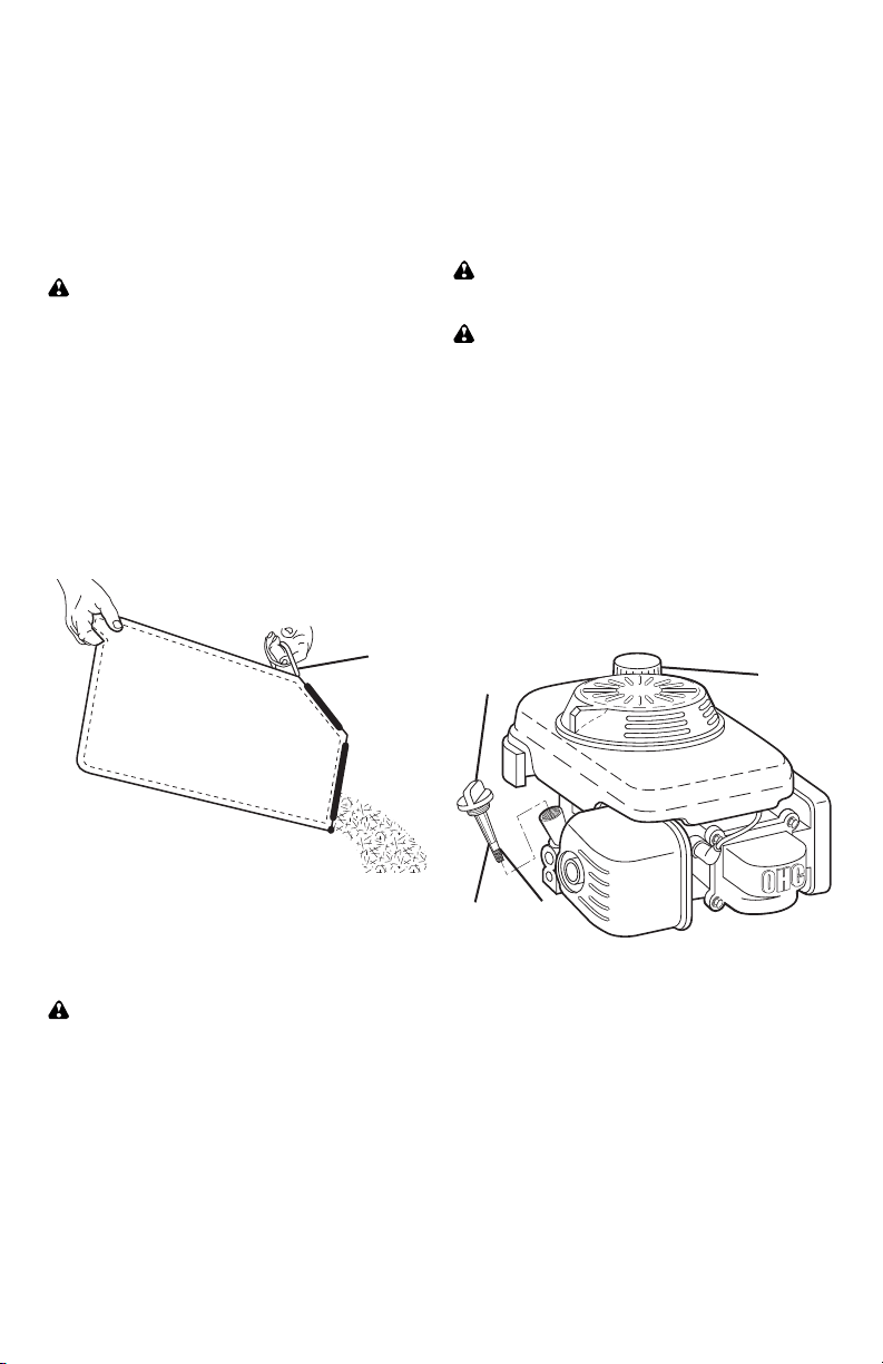
TO EMPTY GRASS CATCHER
1. Lift up on grass catcher using the
frame han dle.
2. Remove grass catcher with clippings
from under lawn mower han dle.
3. Empty clippings from bag.
NOTE: Do not drag the bag when empty-
ing; it will cause unnecessary wear.
CHANGE ENGINE OIL” in the Mainte-
nance section of this manual.
ADD GASOLINE
• Fill fuel tank to bottom of tank filler
neck. Do not overfill. Use fresh, clean,
regular unleaded gasoline with a mini-
mum of 87 octane. Do not mix oil with
gasoline. Purchase fuel in quan ti ties
that can be used within 30 days to as-
sure fuel freshness.
CAUTION: Wipe off any spilled oil or
fuel. Do not store, spill or use gasoline
near an open flame.
CAUTION: Alcohol blended fuels
(called gasohol or using ethanol or meth-
anol) can attract moisture which leads to
separation and for ma tion of acids during
storage. Acidic gas can damage the fuel
system of an engine while in storage. To
avoid engine problems, the fuel system
should be emptied before stor age of 30
days or longer. Empty the gas tank, start
the engine and let it run until the fuel lines
and carburetor are empty. Use fresh fuel
next season. See Storage In struc tions for
additional information. Never use engine
or carburetor cleaner products in the fuel
tank or permanent damage may occur.
Grass
catcher
frame
handle
Oil fill cap /
dipstick
Gasoline
filler cap
Lower
mark
Upper
mark
BEFORE
STARTING ENGINE
ADD OIL
Your lawnmower is shipped without oil in
the engine. For type and grade of oil to
use, see “EN GINE” in the Maintenance
section of this manual.
CAUTION: DO NOT overfill engine with
oil, or it will smoke on startup.
1. Be sure lawnmower is level.
2. Remove oil dipstick from oil fill spout.
3. You recieve a container of oil with the
unit. Slowly pour the entire container
down the oil fill spout into the engine.
4. Insert and tighten dipstick.
IMPORTANT:
• Check oil level before each use. Add
oil if needed. Fill to full line on dipstick.
• Change the oil after every 25 hours of
operation or each season. You may
need to change the oil more often
under dusty, dirty conditions. See “TO
TO STOP ENGINE
• To stop engine, release operator pres-
ence control bar. Wait until blade and
all moving parts have stopped and turn
fuel valve to OFF position if you do not
intend to re start the engine soon.
TO START ENGINE
NOTE: Due to protective coatings on the
engine, a small amount of smoke may be
present during the initial use of the prod-
uct and should be considered normal.
1. Be sure fuel valve is in ON po si tion.
2. Hold operator presence control bar
down to the han dle and pull starter
handle quickly. Do not allow starter
rope to snap back.
23
CYLINDER BARREL
KEY PART
NO. NO. DESCRIPTION
1 12000-Z0L-406 Cylinder Assembly
12000-Z0L-840 Cylinder Assembly
3 12310-Z0J-000 Cover, Cylinder Head
12311-ZL8-D00 Cover, Head
12311-ZL8-000 Cover, Head
4 12355-ZL8-000 Cover, Breather
(Breather Valve Assembly)
5 90013-883-000 Bolt, Flange (#6 x 12)
(CT200)
6 90014-952-000 Bolt, Flange (#6 x 14)
(CT200)
7 91201-ZL8-003 Oil Seal (25.4 x 62 x 6)
8 98079-55846 Spark Plug (BPR5ES)
(NGK)
10 12209-ZM0-003 Seal, Valve Stem
11 14711-ZL8-000 Valve, Intake
(Technostar)
14711-Z0J-000 Valve, Intake (Rocknel)
14711-Z0J-800 Valve, Intake
12 14721-ZL8-000 Valve, Exhaust
13 14751-ZL8-000 Spring, Valve
14 14771-Z0J-000 Retainer, Valve Spring
CARBURETOR
KEY PART
NO. NO. DESCRIPTION
1 16010-883-015 Gasket Set
2 16013-ZL1-003 Float Set
3 16015-Z0L-881 Chamber Set, Float
5 16028-ZE0-005 Screw Set
16028-ZK7-S91 Screw Set
7 16100-Z0L-852 Carburetor Assembly
(BB62Z B)
8 16155-ZM0-013 Valve, Float
9 16166-ZM0-003 Nozzle, Main
10 16211-ZL8-000 Insulator, Carburetor
11 16212-ZL8-000 Gasket, Insulator
13 16228-ZL8-000 Gasket, Carburetor
15 93500-05006-0H Screw, Pan (#5 x 6)
16 99101-124-0600 Jet, Main (#60)
99101-124-0620 Jet, Main (#62)
99101-124-0650 Jet, Main (#65)
26 16951-Z0L-000 Guide, Air
CONTROL
KEY PART
NO. NO. DESCRIPTION
1 16551-ZM0-010 Arm, Governor
2 16555-Z0L-801 Rod, Governor
3 16561-Z0L-000 Spring, Governor
4 16562-ZM0-000 Spring, Throttle Return
10 90015-ZE5-010 Bolt, Governor Arm
13 94050-06000 Nut, Flange (6 mm)
15 93892-04012-00 Screw, Washer Head
(#4 x 12)
16 94103-04000 Washer, Plain (4 mm)
CRANKSHAFT
KEY PART
NO. NO. DESCRIPTION
3 13310-ZM0-610 Crankshaft
5 90402-ZL8-000 Washer, Thrust
RECOIL STARTER
KEY PART
NO. NO. DESCRIPTION
1 28400-Z0L-V20ZA Starter Assembly,
Recoil, “NH1”
(Long Rope) (Black)
8 28461-ZL8-003 Grip, Recoil Starter
9 28462-Z0L-V20 Rope, Recoil Starter,
“Long Type” (Black)
11 90201-ZM0-000 Nut, Flange (6 mm)
MODEL NUMBER GCV160-LAOS3B
HONDA 4-CYCLE ENGINE
22
MODEL NUMBER GCV160-LAOS3B
HONDA 4-CYCLE ENGINE
11
• Keep top of engine around starter clear
and clean of grass clippings and chaff.
This will help engine air flow and extend
engine life.
MULCHING MOWING TIPS
IMPORTANT: For best performance,
keep mower housing free of built-up
grass and trash. See “CLEANING” in the
Maintenance section of this manual.
• The special mulching blade will recut
the grass clip pings many times and
reduce them in size so that as they fall
onto the lawn they will disperse into
the grass and not be noticed. Also,
the mulched grass will bio de grade
quick ly to provide nu tri ents for the lawn.
Always mulch with your highest engine
(blade) speed as this will provide the
best recutting action of the blades.
• Avoid cutting your lawn when it is wet.
Wet grass tends to form clumps and
in ter feres with the mulch ing action. The
best time to mow your lawn is the early
afternoon. At this time the grass has
dried, yet the newly cut area will not be
exposed to direct sunlight.
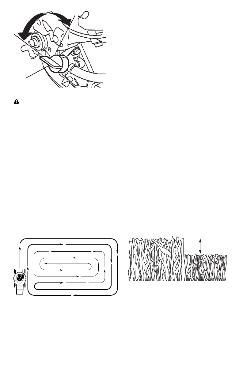
• For best results, adjust the lawn mower
cutting height so that the lawn mower
cuts off only the top one-third of the
grass blades. If the lawn is over grown
it will be nec es sary to raise the height
of cut to reduce pushing effort and to
keep from over load ing the engine and
leaving clumps of mulched grass. For
ex tremely heavy grass, reduce your
width of cut by overlapping previously
cut path and mow slowly.
• Certain types of grass and grass
con di tions may re quire that an area be
mulched a second time to com pletely
hide the clip pings. When doing a sec-
ond cut, mow across (perpendicular) to
the first cut path.
• Change your cutting pattern from week
to week. Mow north to south one week
then change to east to west the next
week. This will help prevent matting
and graining of the lawn.
MAX 1/3
MOWING TIPS
CAUTION: Do not use de-thatcher
blade attachments on your mower. Such
attachments are hazardous, will damage
your mower and could void your warranty.
• Under certain conditions, such as very
tall grass, it may be necessary to raise
the height of cut to reduce pushing effort
and to keep from over load ing the en gine
and leaving clumps of grass clippings. It
may also be necessary to reduce ground
speed and/or run the lawn mower over
the area a second time.
• For extremely heavy cutting, reduce the
width of cut by overlapping pre vi ous ly
cut path and mow slowly.
• For side discharge operation, cut in
a coun ter clock wise di rec tion, start ing
at the outside of the area to be cut, in
order to spread grass clip pings more
evenly and to put less load on the
engine. To keep clip pings off of walk-
ways, flower beds, etc., make the first
cuts in a clock wise direction.
Fuel
valve
lever
ON
OFF
• If a trail of grass clipping is left on the
right side of the lawn mower during rear
discharge operation, mow in a clock-
wise direction with a small overlap to
collect the clippings on the next pass.
• Pores in cloth grass catchers can be-
come filled with dirt and dust with use
and catchers will collect less grass. To
prevent this, regularly hose catcher off
with water and let dry before using.
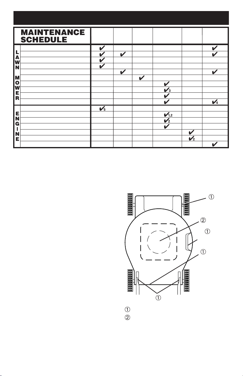
12
Check for Loose Fasteners
Clean / Inspect Grass Catcher *
Check Tires
Check Drive Wheels ***
Clean Lawn Mower ****
Clean under Drive Cover ***
Check Drive Belt / Pulleys ***
Check / Sharpen / Replace Blade
Lubrication
Clean and Recharge Battery **
Check Engine Oil level
Change Engine Oil
Clean Air Filter
Inspect Muffler
Replace Spark Plug
Replace Air Filter Paper Cartridge
Empty fuel system or add Stabilizer
BEFORE
EACH
USE
AFTER
EACH
USE
EVERY
10
HOURS
EVERY
25 HOURS
OR SEASON
EVERY
100
HOURS
BEFORE
STORAGE
1 - Change more often if operating under a heavy load or in high outdoor temperatures.
2 - Service more often if operating in dirty or dusty conditions.
3 - Replace blades more often when mowing in sandy soil.
4 - Charge 48 hours at end of season.
5 - And after each 5 hours of use.
(if so equipped)
Electric-Start mowers
Power-Propelled mowers
Use a scraper
to clean under deck
*
**
***
****
MAINTENANCE
GENERAL REC OM MEN DA TIONS
The warranty on this lawn mower does not
cover items that have been sub ject ed to
operator abuse or negligence. To receive
full value from the warranty, operator must
maintain unit as in struct ed in this manual.
Some adjustments will need to be made
periodically to properly maintain your unit.
At least once a season, check to see if
you should make any of the adjustments
described in the Service and Ad just ments
section of this manual.
• At least once a year, replace the spark
plug, clean or replace air filter element
and check blade for wear. A new spark
plug and clean/new air filter element
assure proper air-fuel mix ture and help
your engine run bet ter and last longer.
• Follow the maintenance schedule in this
manual.
BEFORE EACH USE
• Check engine oil level.
• Check for loose fasteners.
LUBRICATION
Keep unit well lubricated
(See “LU BRI CA TION CHART”).
LUBRICATION CHART
Spray lubricant
See "ENGINE" in Maintenance section.
IMPORTANT: Do not oil or grease plastic
wheel bearings. Viscous lu bri cants will
attract dust and dirt that will short en the life
of the self-lu bri cat ing bearings. If you feel
they must be lu bri cated, use only a dry,
pow dered graphite type lubricant spar ingly.
Wheel
adjuster (on
each wheel)
Engine oil
Rear door
hinge
Handle bracket mounting pins
Mulcher
door hinge pin
21
CRAFTSMAN ROTARY LAWN MOWER - - MODEL NUMBER 944.364152
NOTE: All component dimensions given in U.S. inches. 1 inch = 25.4 mm.
IMPORTANT: Use only Original Equipment Manufacturer (O.E.M.) replacement parts. Failure to do so could be hazardous, damage your lawn mower and void your warranty.
31 165760 Discharge Deflector
32 440858X004 Selector Spring, Rear
33 701037 Selector Knob
34 401176X004 Axle Arm Assembly, Rear, LH
35 426589 Locknut, Hex 5/16-18
36 401638 Bolt, Shoulder 5/16-18
37 194230X427 Wheel & Tire Assembly, Front
39 409149 Nut, Hex
40 411949 Frame, Grassbag
41 194186 Hinge Screw
42 405421 Spring, Rear Door, LH
43 405423 Spring, Rear Door, RH
44 184193 Bolt, Rear Door
45 150406 Screw, Hex Head, Threaded,
Rolled 3/8-16 x 1
46 404763 Danger Decal
47 751153 Locknut, Hex 5/16-18
48 401177X004 Axle Arm Assembly, Rear, RH
49 431880X427 Wheel & Tire Assembly, Rear
50 408955 Grassbag
51 147286 Hinge Rod
52 441963 Kit, Mower Housing
(Includes Key Number 46)
53 851084 Screw, Hex Head, Grade 8
3/8-24 x 1-3/8
54 850263 Helical Lockwasher
KEY PART
NO. NO. DESCRIPTION
1 194176X428 Control Bar
2 447814X479 Upper Handle
3 580638602 Bar, Lower Handle
4 581902101 Rope Guide
5 581912601 T-Knob
6 191574 Handle Bolt
7 66426 Wire Tie
8 74780512 Bolt, Hex Head 5/16-18 x 3/4
9 154132 Hinge Bracket
10 165754 Mulcher Door
11 440934 Engine Zone Control Cable
12 178848 Hex Washer Head Screw
13 429930X004 Up-Stop Bracket
14 189713X428 Handle Knob
15 51793 Hairpin Cotter
18 17600406 Screw 1/4-20 x 3/8
19 401174X004 Axle Arm Assembly, Front, LH
20 401175X004 Axle Arm Assembly, Front, RH
21 416860 Rear Skirt
22 401621X004 Selector Spring, Front
23 401814X428 Rear Door Assembly
25 580915602 Handle Bracket Assembly, LH
26 580915702 Handle Bracket Assembly, RH
29 407494X005 Wheel Adjusting Bracket
30 401629 Spacer
KEY PART
NO. NO. DESCRIPTION
55 851074 Hardened Washer
56 406712 21" Blade
57 418373 Blade Adapter
58 152124 Hinge Spring
59 - - - Engine, Honda GCV160-
LAOS3B (See Breakdown)
61 409148 Locknut, Hex, Flanged
62 73800400 Locknut, Hex 1/4-20
65 88348 Washer, Flat
66 197480 O-Ring
73 401630 Washer, Curved, Cylindrical
74 851201X004 Washer, Special, Engine,
Zinc-Plated
76 410589 Baffle, Rear
77 17411312 Screw, Rear Baffle
83 428501 Baffle, Front
84 17000510 Screw, Front Baffle
87 437516 Plug, Handle Bar
88 586212501 Bolt, Carriage
89 73970500 Nut, Hex
- - 404764 Warning Decal (not shown)
- - 581276301 Bag of Parts (Includes Key
Numbers 88 and 89)
- - 587785901 Owner’s Manual, English
- - 587785902 Owner’s Manual, French
KEY PART
NO. NO. DESCRIPTION

20
REPAIR PARTS
CRAFTSMAN ROTARY LAWN MOWER - - MODEL NUMBER 944.364152
1 2
9
10
11
12
13
15
88
18
23
31
35
35
47
42
43
44
44
46
51
52
84
84
83
53
54
55
56
57
58
62
45
74
8
25
30
32
33
34
36
40
50
65
66
73
8
26
89
30
32
33
48
36
65
66
73
76
77
41
41
47
21
3
6
87
7
89
39
49
39
49
59
20
22
30
36
33
73
36
19
22
30
33
73
29
29
37
61
37
61
14
14
5
4
13
LAWN MOWER
Always observe safety rules when per-
form ing any main te nance.
TIRES
• Keep tires free of gasoline, oil, or insect
control chemi cals which can harm rubber.
• Avoid stumps, stones, deep ruts, sharp
objects and other hazards that may
cause tire damage.
BLADE CARE
For best results, blade must be kept
sharp. Re place a bent or dam aged blade.
CAUTION: Use only a replacement
blade approved by the manufacturer of
your mower. Using a blade not approved
by the manufacturer of your mower is
hazardous, could damage your mower
and void your warranty.
TO REMOVE BLADE
1. Disconnect spark plug wire from spark
plug and place wire where it cannot
come in contact with plug.
2. Turn lawn mower on its side. Make
sure air filter and carburetor are up.
3. Use a wood block between blade and
mower hous ing to prevent blade from
turning when re mov ing blade bolt.
NOTE: Protect your hands with gloves
and/or wrap blade with heavy cloth.
4. Remove blade bolt by turning counter-
clockwise.
5. Remove blade and attaching hard ware
(bolt, lock wash er, hardened wash er).
NOTE: Remove the blade adapter and check
the key inside hub of blade adapter. The key
must be in good con di tion to work properly.
Replace adapter if damaged.
TO REPLACE BLADE
1. Position the blade adapter on the engine
crank shaft. Be sure key in adapter and
crankshaft keyway are aligned.
2. Position blade on the blade adapter
aligning the two (2) holes in the blade
with the raised lugs on the adapter.
3. Be sure the trailing edge of blade (op-
posite sharp edge) is up toward engine.
4. Install the blade bolt with the lock
washer and hardened washer into
blade adapter and crankshaft.
5. Use block of wood between blade and
lawn mower housing and tighten the
blade bolt, turning clockwise.
• The recommended tightening torque is
35–40 ft. lbs. (47–54 Nm).
IMPORTANT: Blade bolt is heat treated.
If bolt needs replacing, replace only with
approved bolt shown in the Repair Parts
section of this manual.
Blade
bolt
Crankshaft
keyway
Hardened
washer
Lockwasher
Blade adapter Key
Blade
Trailing edge
Crankshaft
TO SHARPEN BLADE
NOTE: We do not recommend sharp-
en ing blade - but if you do, be sure the
blade is balanced. An un bal anced blade
will cause eventual damage to lawn
mower or engine.
• The blade can be sharp ened with a file
or on a grinding wheel. Do not attempt
to sharpen while on the mower.
• To check blade balance, drive a nail into
a beam or wall. Leave about one inch of
the straight nail ex posed. Place center
hole of blade over the head of the nail.
If blade is balanced, it should remain in
a horizontal position. If either end of the
blade moves downward, sharpen the
heavy end until the blade is balanced.
GRASS CATCHER
• The grass catcher may be hosed with
water, but must be dry when used.
• Check your grass catcher often for dam-
age or de te ri o ra tion. Through normal use
it will wear. If catcher needs replacing,
replace only with ap proved replacement
catcher shown in the Repair Parts section
of this manual. Give the lawn mower model
number when ordering.
ENGINE
Maintenance, repair, or replacement of the
emission control devices and systems, which
are being done at the customers expense,
may be performed by any non-road engine
repair establishment or individual. Warranty
repairs must be performed by an authorized
engine manufacturer’s service outlet.
LUBRICATION
Use only high quality detergent oil rated with
API service classification SG–SL. Select the
oil's SAE viscosity grade according to your
expected operating temperature.
14
4. Wipe off any spilled oil from lawn
mower or side of engine.
5. Fill engine with oil. The engine oil
capacity is 0.58 quarts. If oil is not
com plete ly drained from engine, you
may not need the entire container of a
20 oz. bottle of oil. Slowly pour 3/4 of
the oil from the container down the oil
fill spout into the engine.
6. Wait one minute to allow oil to settle.
Use guage on oil fill cap/dipstick for
checking level. Insert dipstick into
the tube and rest the oil fill cap on the
tube. DO NOT thread the cap into the
tube when taking reading.
7. Continue adding small amounts of
oil and rechecking the dipstick until it
reads full. DO NOT overfill, or engine
will smoke on startup.
8. Always be sure to retighten oil dipstick
before starting engine.
9. Reconnect spark plug wire to plug.
MUFFLER
Inspect and replace corroded muffler as it
could create a fire hazard and/or dam age.
SPARK PLUG
Replace spark plug at the beginning of
each mowing season or after every 100
hours of operation, whichever occurs
first. Spark plug type and gap setting
are shown in the “PROD UCT SPEC I FI CA-
TIONS” section of this manual.
NOTE: Multi-viscosity oils (5W30, 10W30
etc.) improve starting in cold weather, and
you should check your engine oil level fre-
quently to avoid possible engine damage
from running low on oil.
Change the oil after every 25 hours of opera-
tion or at least once a year if the lawn mower
is not used for 25 hours in one year.
Check the crankcase oil level before
starting the engine and after each five (5)
hours of continuous use. Tighten oil plug
securely each time you check the oil level.
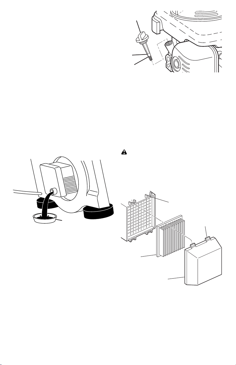
TO CHANGE ENGINE OIL
NOTE: Before tipping lawn mower to
drain oil, empty fuel tank by running en-
gine until fuel tank is empty.
1. Disconnect spark plug wire from spark
plug and place wire where it cannot
come in contact with plug.
2. Remove engine oil cap; lay aside on a
clean surface.
3. Tip lawn mower on its side as shown
and drain oil into a suitable container.
Rock lawn mower back and forth to re-
move any oil trapped inside of engine.
Container
Oil fill cap /
dipstick
Lower
mark
Upper
mark
AIR FILTER
Your engine will not run properly and may
be damaged by using a dirty air filter.
Replace the air filter every 100 hours of
operation or every season, whichever oc-
curs first. Service air cleaner more often
under dusty conditions.
TO CLEAN AIR FILTER
1. Remove cover.
2. Carefully remove cartridge.
3. Clean by gently tapping on a flat sur-
face. If very dirty, replace cartridge.
CAUTION: Petroleum solvents, such
as ker o sene, are not to be used to clean
car tridge. They may cause de te ri o ra tion
of the cartridge. Do not oil car tridge. Do
not use pres sur ized air to clean or dry
car tridge.
4. Install cartridge, then replace cover.
Tab
Cartridge
Filter cover
Slot
19
Loss of power 1. Rear of mower housing or 1. Raise cutting height.
blade dragging in grass.
2. Cutting too much grass. 2. Raise cutting height.
3. Dirty air filter. 3. Clean/replace air filter.
4. Buildup of grass, leaves, 4. Clean underside of mower
and trash under mower. housing.
5. Too much oil in engine. 5. Check oil level.
6. Walking speed too fast. 6. Cut at slower walking speed.
Poor cut – 1. Worn, bent or loose blade. 1. Replace blade. Tighten
uneven blade bolt.
2. Wheel heights uneven. 2. Set all wheels at same
height.
3. Buildup of grass, leaves 3. Clean underside of
and trash under mower. mower housing.
Excessive 1. Worn, bent or loose blade. 1. Replace blade. Tighten
vibration blade bolt.
2. Bent engine crankshaft. 2. Contact a Sears or other
qualified service centre.
Starter rope 1. Engine flywheel brake is on 1. Depress control bar to
hard to pull when control bar is released. upper handle before
pulling the starter rope.
2. Bent engine crankshaft. 2. Contact a Sears or other
qualified service centre.
3. Blade adapter broken. 3. Replace blade adapter.
4. Blade dragging in grass. 4. Move lawn mower to cut
grass or to hard surface.
Grass catcher 1. Cutting height too low. 1. Raise cutting height.
not filling 2. Lift on blade worn off. 2. Replace blade.
(If so equipped) 3. Catcher not venting air. 3. Clean grass catcher.
Hard to push 1. Grass is too high or wheel 1. Raise cutting height.
height is too low.
2. Rear of mower housing or 2. Raise rear of mower housing
blade dragging in grass. one (1) setting higher.
3. Grass catcher too full. 3. Empty grass catcher.
4. Handle height position not 4. Adjust handle height to suit.
right for you.
PROBLEM CAUSE CORRECTION
TROUBLESHOOTING - See appropriate section in manual unless directed
to a Sears Parts & Repair Centre.
18
Does not start 1. Dirty air filter. 1. Clean/replace air filter.
2. Out of fuel. 2. Fill fuel tank.
3. Stale fuel. 3. Empty fuel tank and refill tank
with fresh, clean gasoline.
4. Water in fuel. 4. Empty fuel tank and refill tank
with fresh, clean gasoline.
5. Spark plug wire is 5. Connect wire to plug.
disconnected.
6. Bad spark plug. 6. Replace spark plug.
7. Loose blade or broken 7. Tighten blade bolt or
blade adapter. replace blade adapter.
8. Control bar in released 8. Depress control bar to
position. handle.
9. Control bar defective. 9. Replace control bar.
10. Fuel valve lever (if so 10. Turn fuel valve lever
equipped) in OFF position. to the ON position.
11. Weak battery (if equipped). 11. Charge battery.
12. Disconnected battery 12. Connect battery to engine.
connector (if equipped).
PROBLEM CAUSE CORRECTION
TROUBLESHOOTING - See appropriate section in manual unless directed
to a Sears Parts & Repair Centre.
15
SERVICE AND ADJUSTMENTS
WARNING: To avoid serious injury, before per form ing any service or ad just ments:
1. Release control bar and stop engine.
2. Make sure the blade and all moving parts have completely stopped.
3. Disconnect spark plug wire from spark plug and place wire where it cannot come in
contact with plug.
Lower handle
Handle
bracket
Hairpin cotter
SQUEEZE
TO ADJUST
Mounting pin
CLEANING
IMPORTANT: For best performance,
keep mower housing free of built-up grass
and trash. Clean the underside of your
mower after each use.
CAUTION: Disconnect spark plug wire
from spark plug and place wire where it
cannot come in contact with plug.
• Clean the underside of your lawn
mower by scraping to remove build-up
of grass and trash.
• Clean engine often to keep trash from
accumulating. A clogged engine runs
hotter and shortens engine life.
• Keep finished surfaces and wheels free
of all gasoline, oil, etc.
• With the exception of the water washout
port (if equipped), we do not recommend
using a garden hose to clean the outside
of your lawn mower unless the elec tri cal
system, muffler, air filter and carburetor
are covered to keep water out. Water in
engine can result in shortened engine life.
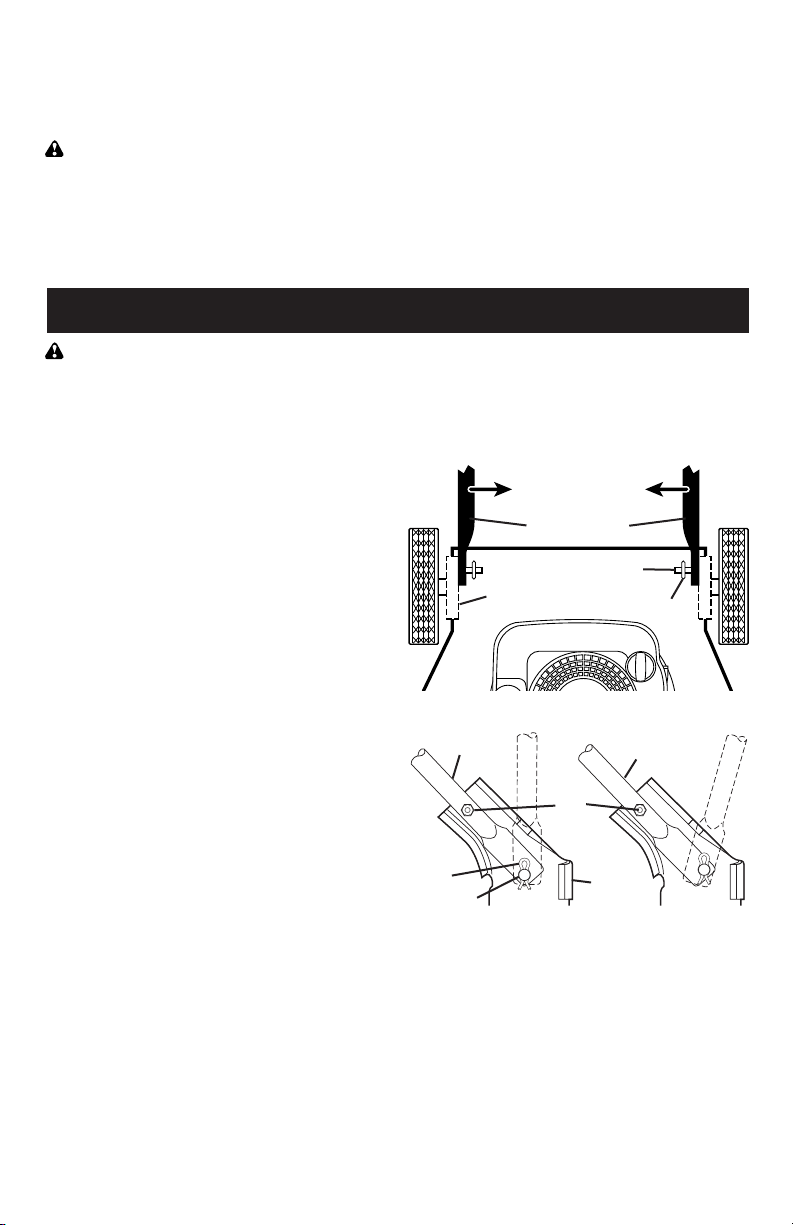
Mowing
position
Mowing
position
HIGH POSITIONLOW POSITION
Handle
bracket
Bolt
and
nut
Hairpin
cotter
Mounting
pin
LAWN MOWER
TO ADJUST CUTTING HEIGHT
See “TO ADJUST CUTTING HEIGHT” in
the Operation sec tion of this manual.
REAR DEFLECTOR
The rear deflector, attached between the
rear wheels of your mower, is provided to
minimize the possibility that objects will
be thrown out of the rear of the mower
into the operator mowing position. Re-
place the deflector if dam aged.
TO ADJUST HANDLE
The handle can be mounted in a high or
low position. The mounting holes in the
bottom of lower handle are off center for
raising or lowering the handle.
1. Remove upper handle and wire tie(s)
securing cable(s) to lower handle.
2. Remove hairpin cotters from lower
handle bracket mount ing pin.
3. Remove bolts and nuts.
4. Squeeze lower handle in to remove it
from mounting pins.
5. Turn lower handle over to raise or
lower handle.
6. Squeeze lower handle in and po si tion
holes onto mount ing pins on handle
bracket.
7. Reinstall bolts and nuts.
8. Reassemble upper handle and all
parts removed from lower handle.
ENGINE
Maintenance, re pair, or re place ment of the
emission con trol de vic es and sys tems, which
are be ing done at the cus tom ers expense,
may be performed by any non-road engine
repair es tab lish ment or individual. Warranty
repairs must be performed by an authorized
engine man u fac tur er's service outlet.
16
ENGINE SPEED
Your engine speed has been factory set.
CARBURETOR
Your carburetor is not adjustable. If your
engine does not operate properly due to
suspected carburetor problems, take your
lawn mower to a Sears or other qualified
service center for repair and/or ad just-
ment.
IMPORTANT: Never tamper with the
engine governor, which is factory set
for proper engine speed. Over speed-
ing the engine above the factory high
speed setting can be dangerous. If you
think the engine-governed high speed
needs adjusting, contact a Sears or other
qualified service centre, which has proper
equip ment and ex pe ri ence to make any
nec es sary adjustments.
STORAGE
Immediately prepare your lawn mower for
storage at the end of the season or if the
unit will not be used for 30 days or more.
LAWN MOWER
When lawn mower is to be stored for a
period of time, clean it thor oughly, remove
all dirt, grease, leaves, etc. Store in a
clean, dry area.
1. Clean entire lawn mower (See
“CLEANING” in the Maintenance sec-
tion of this manual).
2. Lubricate as shown in the Main te-
nance section of this manual.
3. Be sure that all nuts, bolts, screws,
and pins are securely fas tened.
Inspect moving parts for damage,
breakage and wear. Replace if neces-
sary.
4. Touch up all rusted or chipped paint
surfaces; sand lightly before painting.
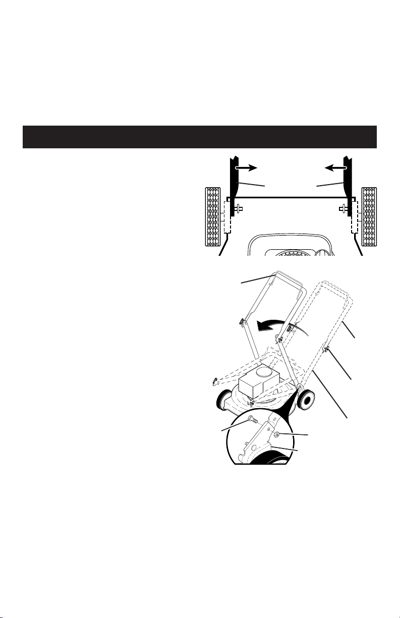
HANDLE
You can fold your lawn mower handle for
storage.
1. Remove bolts and nuts.
2. Squeeze the bottom ends of the
lower handle toward each other until
the lower handle clears the handle
bracket, then move handle forward.
3. Loosen upper handle mounting bolts
enough to allow upper handle to be
folded back.
IMPORTANT: When folding the handle
for storage or transportation, be sure to
fold the handle as shown or you may
damage the control cables.
• When setting up your handle from the
storage position, the lower han dle will
automatically lock into the mow ing
position.
Lower handle
SQUEEZE
TO FOLD
ENGINE
Maintenance, re pair, or re place ment of the
emission con trol de vic es and sys tems, which
are be ing done at the cus tom ers expense,
may be performed by any non-road engine
repair es tab lish ment or individual. Warranty
repairs must be performed by an authorized
engine man u fac tur er's service outlet.
MOWING
POSITION
Lower handle
Operator
presence
control bar
Upper
handle
Handle
knob
FOLD
FORWARD
FOR
STORAGE
Nut
Bracket
Bolt
17
FUEL SYS TEM
IMPORTANT: It is important to prevent
gum deposits from forming in essential
fuel system parts such as carburetor, fuel
filter, fuel hose or tank during storage.
Also, alcohol blended fuels (called
gasohol or using ethanol or methanol)
can attract moisture which leads to
separation and formation of acids during
storage. Acidic gas can damage the fuel
system of an engine while in storage.
• Empty the fuel tank by starting the en-
gine and letting it run until the fuel lines
and car bu re tor are empty.
• Never use engine or carburetor cleaner
prod ucts in the fuel tank or per ma nent
damage may occur.
• Use fresh fuel next season.
NOTE: Fuel stabilizer is an acceptable
al ter na tive in minimizing the formation
of fuel gum deposits during stor age.
Add stabilizer to gasoline in fuel tank or
storage con tain er. Always follow the mix
ratio found on stabilizer container. Run
engine at least 10 min utes after adding
stabilizer to allow the stabilizer to reach
the car bu re tor. Do not empty the gas tank
and carburetor if using fuel stabilizer.
ENGINE OIL
Drain oil (with engine warm) and replace
with clean engine oil. (See “ENGINE” in
the Maintenance section of this manual).
CYLINDER
1. Remove spark plug.
2. Pour 1 ounce/29 ml of oil through
spark plug hole into cylinder.
3. Pull starter handle slowly a few times
to dis trib ute oil.
4. Replace with new spark plug.
OTHER
• Do not store gasoline from one season
to another.
• Replace your gasoline can if your can
starts to rust. Rust and/or dirt in your
gasoline will cause problems.
• If possible, store your unit indoors and
cover it to protect it from dust and dirt.
• Cover your unit with a suitable pro tec-
tive cover that does not retain moisture.
Do not use plastic. Plastic cannot
breathe, which allows con den sa tion to
form and will cause your unit to rust.
IMPORTANT: Never cover mower while
en gine and exhaust areas are still warm.
CAUTION: Never store the lawn
mower with gaso line in the tank inside a
build ing where fumes may reach an open
flame or spark. Allow the engine to cool
before storing in any en clo sure.

16
ENGINE SPEED
Your engine speed has been factory set.
CARBURETOR
Your carburetor is not adjustable. If your
engine does not operate properly due to
suspected carburetor problems, take your
lawn mower to a Sears or other qualified
service center for repair and/or ad just-
ment.
IMPORTANT: Never tamper with the
engine governor, which is factory set
for proper engine speed. Over speed-
ing the engine above the factory high
speed setting can be dangerous. If you
think the engine-governed high speed
needs adjusting, contact a Sears or other
qualified service centre, which has proper
equip ment and ex pe ri ence to make any
nec es sary adjustments.
STORAGE
Immediately prepare your lawn mower for
storage at the end of the season or if the
unit will not be used for 30 days or more.
LAWN MOWER
When lawn mower is to be stored for a
period of time, clean it thor oughly, remove
all dirt, grease, leaves, etc. Store in a
clean, dry area.
1. Clean entire lawn mower (See
“CLEANING” in the Maintenance sec-
tion of this manual).
2. Lubricate as shown in the Main te-
nance section of this manual.
3. Be sure that all nuts, bolts, screws,
and pins are securely fas tened.
Inspect moving parts for damage,
breakage and wear. Replace if neces-
sary.
4. Touch up all rusted or chipped paint
surfaces; sand lightly before painting.
HANDLE
You can fold your lawn mower handle for
storage.
1. Remove bolts and nuts.
2. Squeeze the bottom ends of the
lower handle toward each other until
the lower handle clears the handle
bracket, then move handle forward.
3. Loosen upper handle mounting bolts
enough to allow upper handle to be
folded back.
IMPORTANT: When folding the handle
for storage or transportation, be sure to
fold the handle as shown or you may
damage the control cables.
• When setting up your handle from the
storage position, the lower han dle will
automatically lock into the mow ing
position.
Lower handle
SQUEEZE
TO FOLD
ENGINE
Maintenance, re pair, or re place ment of the
emission con trol de vic es and sys tems, which
are be ing done at the cus tom ers expense,
may be performed by any non-road engine
repair es tab lish ment or individual. Warranty
repairs must be performed by an authorized
engine man u fac tur er's service outlet.
MOWING
POSITION
Lower handle
Operator
presence
control bar
Upper
handle
Handle
knob
FOLD
FORWARD
FOR
STORAGE
Nut
Bracket
Bolt
17
FUEL SYS TEM
IMPORTANT: It is important to prevent
gum deposits from forming in essential
fuel system parts such as carburetor, fuel
filter, fuel hose or tank during storage.
Also, alcohol blended fuels (called
gasohol or using ethanol or methanol)
can attract moisture which leads to
separation and formation of acids during
storage. Acidic gas can damage the fuel
system of an engine while in storage.
• Empty the fuel tank by starting the en-
gine and letting it run until the fuel lines
and car bu re tor are empty.
• Never use engine or carburetor cleaner
prod ucts in the fuel tank or per ma nent
damage may occur.
• Use fresh fuel next season.
NOTE: Fuel stabilizer is an acceptable
al ter na tive in minimizing the formation
of fuel gum deposits during stor age.
Add stabilizer to gasoline in fuel tank or
storage con tain er. Always follow the mix
ratio found on stabilizer container. Run
engine at least 10 min utes after adding
stabilizer to allow the stabilizer to reach
the car bu re tor. Do not empty the gas tank
and carburetor if using fuel stabilizer.
ENGINE OIL
Drain oil (with engine warm) and replace
with clean engine oil. (See “ENGINE” in
the Maintenance section of this manual).
CYLINDER
1. Remove spark plug.
2. Pour 1 ounce/29 ml of oil through
spark plug hole into cylinder.
3. Pull starter handle slowly a few times
to dis trib ute oil.
4. Replace with new spark plug.
OTHER
• Do not store gasoline from one season
to another.
• Replace your gasoline can if your can
starts to rust. Rust and/or dirt in your
gasoline will cause problems.
• If possible, store your unit indoors and
cover it to protect it from dust and dirt.
• Cover your unit with a suitable pro tec-
tive cover that does not retain moisture.
Do not use plastic. Plastic cannot
breathe, which allows con den sa tion to
form and will cause your unit to rust.
IMPORTANT: Never cover mower while
en gine and exhaust areas are still warm.
CAUTION: Never store the lawn
mower with gaso line in the tank inside a
build ing where fumes may reach an open
flame or spark. Allow the engine to cool
before storing in any en clo sure.

18
Does not start 1. Dirty air filter. 1. Clean/replace air filter.
2. Out of fuel. 2. Fill fuel tank.
3. Stale fuel. 3. Empty fuel tank and refill tank
with fresh, clean gasoline.
4. Water in fuel. 4. Empty fuel tank and refill tank
with fresh, clean gasoline.
5. Spark plug wire is 5. Connect wire to plug.
disconnected.
6. Bad spark plug. 6. Replace spark plug.
7. Loose blade or broken 7. Tighten blade bolt or
blade adapter. replace blade adapter.
8. Control bar in released 8. Depress control bar to
position. handle.
9. Control bar defective. 9. Replace control bar.
10. Fuel valve lever (if so 10. Turn fuel valve lever
equipped) in OFF position. to the ON position.
11. Weak battery (if equipped). 11. Charge battery.
12. Disconnected battery 12. Connect battery to engine.
connector (if equipped).
PROBLEM CAUSE CORRECTION
TROUBLESHOOTING - See appropriate section in manual unless directed
to a Sears Parts & Repair Centre.
15
SERVICE AND ADJUSTMENTS
WARNING: To avoid serious injury, before per form ing any service or ad just ments:
1. Release control bar and stop engine.
2. Make sure the blade and all moving parts have completely stopped.
3. Disconnect spark plug wire from spark plug and place wire where it cannot come in
contact with plug.
Lower handle
Handle
bracket
Hairpin cotter
SQUEEZE
TO ADJUST
Mounting pin
CLEANING
IMPORTANT: For best performance,
keep mower housing free of built-up grass
and trash. Clean the underside of your
mower after each use.
CAUTION: Disconnect spark plug wire
from spark plug and place wire where it
cannot come in contact with plug.
• Clean the underside of your lawn
mower by scraping to remove build-up
of grass and trash.
• Clean engine often to keep trash from
accumulating. A clogged engine runs
hotter and shortens engine life.
• Keep finished surfaces and wheels free
of all gasoline, oil, etc.
• With the exception of the water washout
port (if equipped), we do not recommend
using a garden hose to clean the outside
of your lawn mower unless the elec tri cal
system, muffler, air filter and carburetor
are covered to keep water out. Water in
engine can result in shortened engine life.
Mowing
position
Mowing
position
HIGH POSITIONLOW POSITION
Handle
bracket
Bolt
and
nut
Hairpin
cotter
Mounting
pin
LAWN MOWER
TO ADJUST CUTTING HEIGHT
See “TO ADJUST CUTTING HEIGHT” in
the Operation sec tion of this manual.
REAR DEFLECTOR
The rear deflector, attached between the
rear wheels of your mower, is provided to
minimize the possibility that objects will
be thrown out of the rear of the mower
into the operator mowing position. Re-
place the deflector if dam aged.
TO ADJUST HANDLE
The handle can be mounted in a high or
low position. The mounting holes in the
bottom of lower handle are off center for
raising or lowering the handle.
1. Remove upper handle and wire tie(s)
securing cable(s) to lower handle.
2. Remove hairpin cotters from lower
handle bracket mount ing pin.
3. Remove bolts and nuts.
4. Squeeze lower handle in to remove it
from mounting pins.
5. Turn lower handle over to raise or
lower handle.
6. Squeeze lower handle in and po si tion
holes onto mount ing pins on handle
bracket.
7. Reinstall bolts and nuts.
8. Reassemble upper handle and all
parts removed from lower handle.
ENGINE
Maintenance, re pair, or re place ment of the
emission con trol de vic es and sys tems, which
are be ing done at the cus tom ers expense,
may be performed by any non-road engine
repair es tab lish ment or individual. Warranty
repairs must be performed by an authorized
engine man u fac tur er's service outlet.

14
4. Wipe off any spilled oil from lawn
mower or side of engine.
5. Fill engine with oil. The engine oil
capacity is 0.58 quarts. If oil is not
com plete ly drained from engine, you
may not need the entire container of a
20 oz. bottle of oil. Slowly pour 3/4 of
the oil from the container down the oil
fill spout into the engine.
6. Wait one minute to allow oil to settle.
Use guage on oil fill cap/dipstick for
checking level. Insert dipstick into
the tube and rest the oil fill cap on the
tube. DO NOT thread the cap into the
tube when taking reading.
7. Continue adding small amounts of
oil and rechecking the dipstick until it
reads full. DO NOT overfill, or engine
will smoke on startup.
8. Always be sure to retighten oil dipstick
before starting engine.
9. Reconnect spark plug wire to plug.
MUFFLER
Inspect and replace corroded muffler as it
could create a fire hazard and/or dam age.
SPARK PLUG
Replace spark plug at the beginning of
each mowing season or after every 100
hours of operation, whichever occurs
first. Spark plug type and gap setting
are shown in the “PROD UCT SPEC I FI CA-
TIONS” section of this manual.
NOTE: Multi-viscosity oils (5W30, 10W30
etc.) improve starting in cold weather, and
you should check your engine oil level fre-
quently to avoid possible engine damage
from running low on oil.
Change the oil after every 25 hours of opera-
tion or at least once a year if the lawn mower
is not used for 25 hours in one year.
Check the crankcase oil level before
starting the engine and after each five (5)
hours of continuous use. Tighten oil plug
securely each time you check the oil level.
TO CHANGE ENGINE OIL
NOTE: Before tipping lawn mower to
drain oil, empty fuel tank by running en-
gine until fuel tank is empty.
1. Disconnect spark plug wire from spark
plug and place wire where it cannot
come in contact with plug.
2. Remove engine oil cap; lay aside on a
clean surface.
3. Tip lawn mower on its side as shown
and drain oil into a suitable container.
Rock lawn mower back and forth to re-
move any oil trapped inside of engine.
Container
Oil fill cap /
dipstick
Lower
mark
Upper
mark
AIR FILTER
Your engine will not run properly and may
be damaged by using a dirty air filter.
Replace the air filter every 100 hours of
operation or every season, whichever oc-
curs first. Service air cleaner more often
under dusty conditions.
TO CLEAN AIR FILTER
1. Remove cover.
2. Carefully remove cartridge.
3. Clean by gently tapping on a flat sur-
face. If very dirty, replace cartridge.
CAUTION: Petroleum solvents, such
as ker o sene, are not to be used to clean
car tridge. They may cause de te ri o ra tion
of the cartridge. Do not oil car tridge. Do
not use pres sur ized air to clean or dry
car tridge.
4. Install cartridge, then replace cover.
Tab
Cartridge
Filter cover
Slot
19
Loss of power 1. Rear of mower housing or 1. Raise cutting height.
blade dragging in grass.
2. Cutting too much grass. 2. Raise cutting height.
3. Dirty air filter. 3. Clean/replace air filter.
4. Buildup of grass, leaves, 4. Clean underside of mower
and trash under mower. housing.
5. Too much oil in engine. 5. Check oil level.
6. Walking speed too fast. 6. Cut at slower walking speed.
Poor cut – 1. Worn, bent or loose blade. 1. Replace blade. Tighten
uneven blade bolt.
2. Wheel heights uneven. 2. Set all wheels at same
height.
3. Buildup of grass, leaves 3. Clean underside of
and trash under mower. mower housing.
Excessive 1. Worn, bent or loose blade. 1. Replace blade. Tighten
vibration blade bolt.
2. Bent engine crankshaft. 2. Contact a Sears or other
qualified service centre.
Starter rope 1. Engine flywheel brake is on 1. Depress control bar to
hard to pull when control bar is released. upper handle before
pulling the starter rope.
2. Bent engine crankshaft. 2. Contact a Sears or other
qualified service centre.
3. Blade adapter broken. 3. Replace blade adapter.
4. Blade dragging in grass. 4. Move lawn mower to cut
grass or to hard surface.
Grass catcher 1. Cutting height too low. 1. Raise cutting height.
not filling 2. Lift on blade worn off. 2. Replace blade.
(If so equipped) 3. Catcher not venting air. 3. Clean grass catcher.
Hard to push 1. Grass is too high or wheel 1. Raise cutting height.
height is too low.
2. Rear of mower housing or 2. Raise rear of mower housing
blade dragging in grass. one (1) setting higher.
3. Grass catcher too full. 3. Empty grass catcher.
4. Handle height position not 4. Adjust handle height to suit.
right for you.
PROBLEM CAUSE CORRECTION
TROUBLESHOOTING - See appropriate section in manual unless directed
to a Sears Parts & Repair Centre.
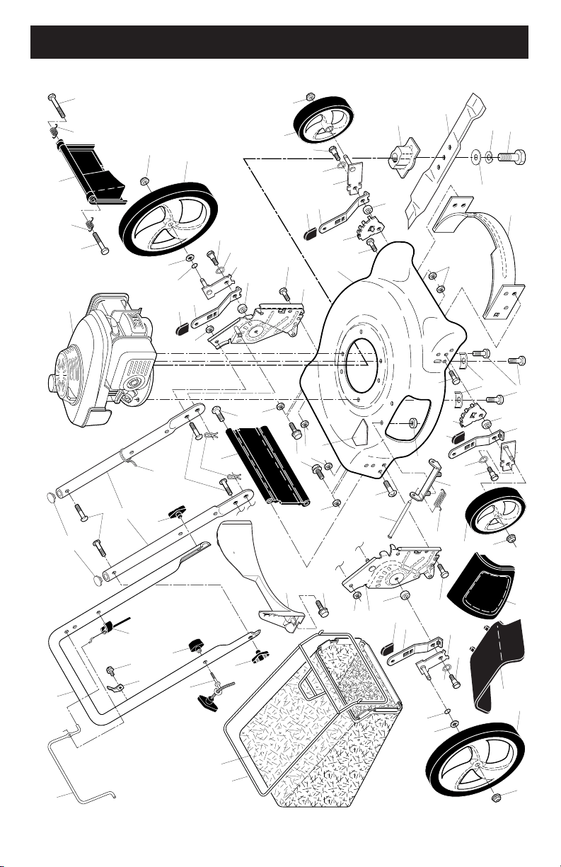
20
REPAIR PARTS
CRAFTSMAN ROTARY LAWN MOWER - - MODEL NUMBER 944.364152
1 2
9
10
11
12
13
15
88
18
23
31
35
35
47
42
43
44
44
46
51
52
84
84
83
53
54
55
56
57
58
62
45
74
8
25
30
32
33
34
36
40
50
65
66
73
8
26
89
30
32
33
48
36
65
66
73
76
77
41
41
47
21
3
6
87
7
89
39
49
39
49
59
20
22
30
36
33
73
36
19
22
30
33
73
29
29
37
61
37
61
14
14
5
4
13
LAWN MOWER
Always observe safety rules when per-
form ing any main te nance.
TIRES
• Keep tires free of gasoline, oil, or insect
control chemi cals which can harm rubber.
• Avoid stumps, stones, deep ruts, sharp
objects and other hazards that may
cause tire damage.
BLADE CARE
For best results, blade must be kept
sharp. Re place a bent or dam aged blade.
CAUTION: Use only a replacement
blade approved by the manufacturer of
your mower. Using a blade not approved
by the manufacturer of your mower is
hazardous, could damage your mower
and void your warranty.
TO REMOVE BLADE
1. Disconnect spark plug wire from spark
plug and place wire where it cannot
come in contact with plug.
2. Turn lawn mower on its side. Make
sure air filter and carburetor are up.
3. Use a wood block between blade and
mower hous ing to prevent blade from
turning when re mov ing blade bolt.
NOTE: Protect your hands with gloves
and/or wrap blade with heavy cloth.
4. Remove blade bolt by turning counter-
clockwise.
5. Remove blade and attaching hard ware
(bolt, lock wash er, hardened wash er).
NOTE: Remove the blade adapter and check
the key inside hub of blade adapter. The key
must be in good con di tion to work properly.
Replace adapter if damaged.
TO REPLACE BLADE
1. Position the blade adapter on the engine
crank shaft. Be sure key in adapter and
crankshaft keyway are aligned.
2. Position blade on the blade adapter
aligning the two (2) holes in the blade
with the raised lugs on the adapter.
3. Be sure the trailing edge of blade (op-
posite sharp edge) is up toward engine.
4. Install the blade bolt with the lock
washer and hardened washer into
blade adapter and crankshaft.
5. Use block of wood between blade and
lawn mower housing and tighten the
blade bolt, turning clockwise.
• The recommended tightening torque is
35–40 ft. lbs. (47–54 Nm).
IMPORTANT: Blade bolt is heat treated.
If bolt needs replacing, replace only with
approved bolt shown in the Repair Parts
section of this manual.
Blade
bolt
Crankshaft
keyway
Hardened
washer
Lockwasher
Blade adapter Key
Blade
Trailing edge
Crankshaft
TO SHARPEN BLADE
NOTE: We do not recommend sharp-
en ing blade - but if you do, be sure the
blade is balanced. An un bal anced blade
will cause eventual damage to lawn
mower or engine.
• The blade can be sharp ened with a file
or on a grinding wheel. Do not attempt
to sharpen while on the mower.
• To check blade balance, drive a nail into
a beam or wall. Leave about one inch of
the straight nail ex posed. Place center
hole of blade over the head of the nail.
If blade is balanced, it should remain in
a horizontal position. If either end of the
blade moves downward, sharpen the
heavy end until the blade is balanced.
GRASS CATCHER
• The grass catcher may be hosed with
water, but must be dry when used.
• Check your grass catcher often for dam-
age or de te ri o ra tion. Through normal use
it will wear. If catcher needs replacing,
replace only with ap proved replacement
catcher shown in the Repair Parts section
of this manual. Give the lawn mower model
number when ordering.
ENGINE
Maintenance, repair, or replacement of the
emission control devices and systems, which
are being done at the customers expense,
may be performed by any non-road engine
repair establishment or individual. Warranty
repairs must be performed by an authorized
engine manufacturer’s service outlet.
LUBRICATION
Use only high quality detergent oil rated with
API service classification SG–SL. Select the
oil's SAE viscosity grade according to your
expected operating temperature.

12
Check for Loose Fasteners
Clean / Inspect Grass Catcher *
Check Tires
Check Drive Wheels ***
Clean Lawn Mower ****
Clean under Drive Cover ***
Check Drive Belt / Pulleys ***
Check / Sharpen / Replace Blade
Lubrication
Clean and Recharge Battery **
Check Engine Oil level
Change Engine Oil
Clean Air Filter
Inspect Muffler
Replace Spark Plug
Replace Air Filter Paper Cartridge
Empty fuel system or add Stabilizer
BEFORE
EACH
USE
AFTER
EACH
USE
EVERY
10
HOURS
EVERY
25 HOURS
OR SEASON
EVERY
100
HOURS
BEFORE
STORAGE
1 - Change more often if operating under a heavy load or in high outdoor temperatures.
2 - Service more often if operating in dirty or dusty conditions.
3 - Replace blades more often when mowing in sandy soil.
4 - Charge 48 hours at end of season.
5 - And after each 5 hours of use.
(if so equipped)
Electric-Start mowers
Power-Propelled mowers
Use a scraper
to clean under deck
*
**
***
****
MAINTENANCE
GENERAL REC OM MEN DA TIONS
The warranty on this lawn mower does not
cover items that have been sub ject ed to
operator abuse or negligence. To receive
full value from the warranty, operator must
maintain unit as in struct ed in this manual.
Some adjustments will need to be made
periodically to properly maintain your unit.
At least once a season, check to see if
you should make any of the adjustments
described in the Service and Ad just ments
section of this manual.
• At least once a year, replace the spark
plug, clean or replace air filter element
and check blade for wear. A new spark
plug and clean/new air filter element
assure proper air-fuel mix ture and help
your engine run bet ter and last longer.
• Follow the maintenance schedule in this
manual.
BEFORE EACH USE
• Check engine oil level.
• Check for loose fasteners.
LUBRICATION
Keep unit well lubricated
(See “LU BRI CA TION CHART”).
LUBRICATION CHART
Spray lubricant
See "ENGINE" in Maintenance section.
IMPORTANT: Do not oil or grease plastic
wheel bearings. Viscous lu bri cants will
attract dust and dirt that will short en the life
of the self-lu bri cat ing bearings. If you feel
they must be lu bri cated, use only a dry,
pow dered graphite type lubricant spar ingly.
Wheel
adjuster (on
each wheel)
Engine oil
Rear door
hinge
Handle bracket mounting pins
Mulcher
door hinge pin
21
CRAFTSMAN ROTARY LAWN MOWER - - MODEL NUMBER 944.364152
NOTE: All component dimensions given in U.S. inches. 1 inch = 25.4 mm.
IMPORTANT: Use only Original Equipment Manufacturer (O.E.M.) replacement parts. Failure to do so could be hazardous, damage your lawn mower and void your warranty.
31 165760 Discharge Deflector
32 440858X004 Selector Spring, Rear
33 701037 Selector Knob
34 401176X004 Axle Arm Assembly, Rear, LH
35 426589 Locknut, Hex 5/16-18
36 401638 Bolt, Shoulder 5/16-18
37 194230X427 Wheel & Tire Assembly, Front
39 409149 Nut, Hex
40 411949 Frame, Grassbag
41 194186 Hinge Screw
42 405421 Spring, Rear Door, LH
43 405423 Spring, Rear Door, RH
44 184193 Bolt, Rear Door
45 150406 Screw, Hex Head, Threaded,
Rolled 3/8-16 x 1
46 404763 Danger Decal
47 751153 Locknut, Hex 5/16-18
48 401177X004 Axle Arm Assembly, Rear, RH
49 431880X427 Wheel & Tire Assembly, Rear
50 408955 Grassbag
51 147286 Hinge Rod
52 441963 Kit, Mower Housing
(Includes Key Number 46)
53 851084 Screw, Hex Head, Grade 8
3/8-24 x 1-3/8
54 850263 Helical Lockwasher
KEY PART
NO. NO. DESCRIPTION
1 194176X428 Control Bar
2 447814X479 Upper Handle
3 580638602 Bar, Lower Handle
4 581902101 Rope Guide
5 581912601 T-Knob
6 191574 Handle Bolt
7 66426 Wire Tie
8 74780512 Bolt, Hex Head 5/16-18 x 3/4
9 154132 Hinge Bracket
10 165754 Mulcher Door
11 440934 Engine Zone Control Cable
12 178848 Hex Washer Head Screw
13 429930X004 Up-Stop Bracket
14 189713X428 Handle Knob
15 51793 Hairpin Cotter
18 17600406 Screw 1/4-20 x 3/8
19 401174X004 Axle Arm Assembly, Front, LH
20 401175X004 Axle Arm Assembly, Front, RH
21 416860 Rear Skirt
22 401621X004 Selector Spring, Front
23 401814X428 Rear Door Assembly
25 580915602 Handle Bracket Assembly, LH
26 580915702 Handle Bracket Assembly, RH
29 407494X005 Wheel Adjusting Bracket
30 401629 Spacer
KEY PART
NO. NO. DESCRIPTION
55 851074 Hardened Washer
56 406712 21" Blade
57 418373 Blade Adapter
58 152124 Hinge Spring
59 - - - Engine, Honda GCV160-
LAOS3B (See Breakdown)
61 409148 Locknut, Hex, Flanged
62 73800400 Locknut, Hex 1/4-20
65 88348 Washer, Flat
66 197480 O-Ring
73 401630 Washer, Curved, Cylindrical
74 851201X004 Washer, Special, Engine,
Zinc-Plated
76 410589 Baffle, Rear
77 17411312 Screw, Rear Baffle
83 428501 Baffle, Front
84 17000510 Screw, Front Baffle
87 437516 Plug, Handle Bar
88 586212501 Bolt, Carriage
89 73970500 Nut, Hex
- - 404764 Warning Decal (not shown)
- - 581276301 Bag of Parts (Includes Key
Numbers 88 and 89)
- - 587785901 Owner’s Manual, English
- - 587785902 Owner’s Manual, French
KEY PART
NO. NO. DESCRIPTION
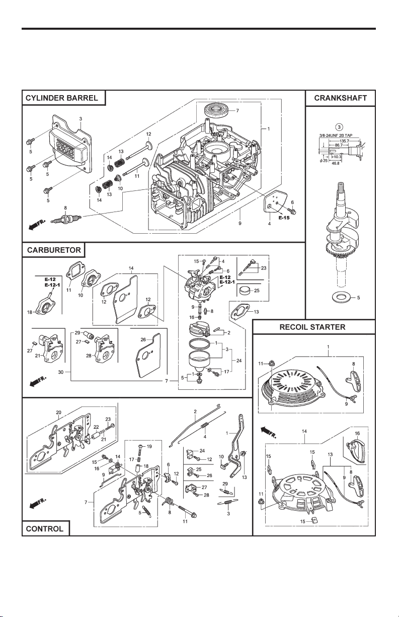
22
MODEL NUMBER GCV160-LAOS3B
HONDA 4-CYCLE ENGINE
11
• Keep top of engine around starter clear
and clean of grass clippings and chaff.
This will help engine air flow and extend
engine life.
MULCHING MOWING TIPS
IMPORTANT: For best performance,
keep mower housing free of built-up
grass and trash. See “CLEANING” in the
Maintenance section of this manual.
• The special mulching blade will recut
the grass clip pings many times and
reduce them in size so that as they fall
onto the lawn they will disperse into
the grass and not be noticed. Also,
the mulched grass will bio de grade
quick ly to provide nu tri ents for the lawn.
Always mulch with your highest engine
(blade) speed as this will provide the
best recutting action of the blades.
• Avoid cutting your lawn when it is wet.
Wet grass tends to form clumps and
in ter feres with the mulch ing action. The
best time to mow your lawn is the early
afternoon. At this time the grass has
dried, yet the newly cut area will not be
exposed to direct sunlight.
• For best results, adjust the lawn mower
cutting height so that the lawn mower
cuts off only the top one-third of the
grass blades. If the lawn is over grown
it will be nec es sary to raise the height
of cut to reduce pushing effort and to
keep from over load ing the engine and
leaving clumps of mulched grass. For
ex tremely heavy grass, reduce your
width of cut by overlapping previously
cut path and mow slowly.
• Certain types of grass and grass
con di tions may re quire that an area be
mulched a second time to com pletely
hide the clip pings. When doing a sec-
ond cut, mow across (perpendicular) to
the first cut path.
• Change your cutting pattern from week
to week. Mow north to south one week
then change to east to west the next
week. This will help prevent matting
and graining of the lawn.
MAX 1/3
MOWING TIPS
CAUTION: Do not use de-thatcher
blade attachments on your mower. Such
attachments are hazardous, will damage
your mower and could void your warranty.
• Under certain conditions, such as very
tall grass, it may be necessary to raise
the height of cut to reduce pushing effort
and to keep from over load ing the en gine
and leaving clumps of grass clippings. It
may also be necessary to reduce ground
speed and/or run the lawn mower over
the area a second time.
• For extremely heavy cutting, reduce the
width of cut by overlapping pre vi ous ly
cut path and mow slowly.
• For side discharge operation, cut in
a coun ter clock wise di rec tion, start ing
at the outside of the area to be cut, in
order to spread grass clip pings more
evenly and to put less load on the
engine. To keep clip pings off of walk-
ways, flower beds, etc., make the first
cuts in a clock wise direction.
Fuel
valve
lever
ON
OFF
• If a trail of grass clipping is left on the
right side of the lawn mower during rear
discharge operation, mow in a clock-
wise direction with a small overlap to
collect the clippings on the next pass.
• Pores in cloth grass catchers can be-
come filled with dirt and dust with use
and catchers will collect less grass. To
prevent this, regularly hose catcher off
with water and let dry before using.

10
SIMPLE STEPS TO REMEMBER WHEN
CONVERTING YOUR LAWN MOWER
FOR MULCHING -
1. Rear door closed.
2. Mulcher door closed.
FOR REAR BAGGING -
1. Grass catcher installed.
2. Mulcher door closed.
FOR SIDE DISCHARGING -
1. Rear door closed.
2. Discharge deflector installed.
CAUTION: Do not run your lawn mow-
er with out rear door closed or ap proved
grass catcher in place. Never at tempt to
op er ate the lawn mow er with the rear door
re moved or propped open.
TO EMPTY GRASS CATCHER
1. Lift up on grass catcher using the
frame han dle.
2. Remove grass catcher with clippings
from under lawn mower han dle.
3. Empty clippings from bag.
NOTE: Do not drag the bag when empty-
ing; it will cause unnecessary wear.
CHANGE ENGINE OIL” in the Mainte-
nance section of this manual.
ADD GASOLINE
• Fill fuel tank to bottom of tank filler
neck. Do not overfill. Use fresh, clean,
regular unleaded gasoline with a mini-
mum of 87 octane. Do not mix oil with
gasoline. Purchase fuel in quan ti ties
that can be used within 30 days to as-
sure fuel freshness.
CAUTION: Wipe off any spilled oil or
fuel. Do not store, spill or use gasoline
near an open flame.
CAUTION: Alcohol blended fuels
(called gasohol or using ethanol or meth-
anol) can attract moisture which leads to
separation and for ma tion of acids during
storage. Acidic gas can damage the fuel
system of an engine while in storage. To
avoid engine problems, the fuel system
should be emptied before stor age of 30
days or longer. Empty the gas tank, start
the engine and let it run until the fuel lines
and carburetor are empty. Use fresh fuel
next season. See Storage In struc tions for
additional information. Never use engine
or carburetor cleaner products in the fuel
tank or permanent damage may occur.
Grass
catcher
frame
handle
Oil fill cap /
dipstick
Gasoline
filler cap
Lower
mark
Upper
mark
BEFORE
STARTING ENGINE
ADD OIL
Your lawnmower is shipped without oil in
the engine. For type and grade of oil to
use, see “EN GINE” in the Maintenance
section of this manual.
CAUTION: DO NOT overfill engine with
oil, or it will smoke on startup.
1. Be sure lawnmower is level.
2. Remove oil dipstick from oil fill spout.
3. You recieve a container of oil with the
unit. Slowly pour the entire container
down the oil fill spout into the engine.
4. Insert and tighten dipstick.
IMPORTANT:
• Check oil level before each use. Add
oil if needed. Fill to full line on dipstick.
• Change the oil after every 25 hours of
operation or each season. You may
need to change the oil more often
under dusty, dirty conditions. See “TO
TO STOP ENGINE
• To stop engine, release operator pres-
ence control bar. Wait until blade and
all moving parts have stopped and turn
fuel valve to OFF position if you do not
intend to re start the engine soon.
TO START ENGINE
NOTE: Due to protective coatings on the
engine, a small amount of smoke may be
present during the initial use of the prod-
uct and should be considered normal.
1. Be sure fuel valve is in ON po si tion.
2. Hold operator presence control bar
down to the han dle and pull starter
handle quickly. Do not allow starter
rope to snap back.
23
CYLINDER BARREL
KEY PART
NO. NO. DESCRIPTION
1 12000-Z0L-406 Cylinder Assembly
12000-Z0L-840 Cylinder Assembly
3 12310-Z0J-000 Cover, Cylinder Head
12311-ZL8-D00 Cover, Head
12311-ZL8-000 Cover, Head
4 12355-ZL8-000 Cover, Breather
(Breather Valve Assembly)
5 90013-883-000 Bolt, Flange (#6 x 12)
(CT200)
6 90014-952-000 Bolt, Flange (#6 x 14)
(CT200)
7 91201-ZL8-003 Oil Seal (25.4 x 62 x 6)
8 98079-55846 Spark Plug (BPR5ES)
(NGK)
10 12209-ZM0-003 Seal, Valve Stem
11 14711-ZL8-000 Valve, Intake
(Technostar)
14711-Z0J-000 Valve, Intake (Rocknel)
14711-Z0J-800 Valve, Intake
12 14721-ZL8-000 Valve, Exhaust
13 14751-ZL8-000 Spring, Valve
14 14771-Z0J-000 Retainer, Valve Spring
CARBURETOR
KEY PART
NO. NO. DESCRIPTION
1 16010-883-015 Gasket Set
2 16013-ZL1-003 Float Set
3 16015-Z0L-881 Chamber Set, Float
5 16028-ZE0-005 Screw Set
16028-ZK7-S91 Screw Set
7 16100-Z0L-852 Carburetor Assembly
(BB62Z B)
8 16155-ZM0-013 Valve, Float
9 16166-ZM0-003 Nozzle, Main
10 16211-ZL8-000 Insulator, Carburetor
11 16212-ZL8-000 Gasket, Insulator
13 16228-ZL8-000 Gasket, Carburetor
15 93500-05006-0H Screw, Pan (#5 x 6)
16 99101-124-0600 Jet, Main (#60)
99101-124-0620 Jet, Main (#62)
99101-124-0650 Jet, Main (#65)
26 16951-Z0L-000 Guide, Air
CONTROL
KEY PART
NO. NO. DESCRIPTION
1 16551-ZM0-010 Arm, Governor
2 16555-Z0L-801 Rod, Governor
3 16561-Z0L-000 Spring, Governor
4 16562-ZM0-000 Spring, Throttle Return
10 90015-ZE5-010 Bolt, Governor Arm
13 94050-06000 Nut, Flange (6 mm)
15 93892-04012-00 Screw, Washer Head
(#4 x 12)
16 94103-04000 Washer, Plain (4 mm)
CRANKSHAFT
KEY PART
NO. NO. DESCRIPTION
3 13310-ZM0-610 Crankshaft
5 90402-ZL8-000 Washer, Thrust
RECOIL STARTER
KEY PART
NO. NO. DESCRIPTION
1 28400-Z0L-V20ZA Starter Assembly,
Recoil, “NH1”
(Long Rope) (Black)
8 28461-ZL8-003 Grip, Recoil Starter
9 28462-Z0L-V20 Rope, Recoil Starter,
“Long Type” (Black)
11 90201-ZM0-000 Nut, Flange (6 mm)
MODEL NUMBER GCV160-LAOS3B
HONDA 4-CYCLE ENGINE
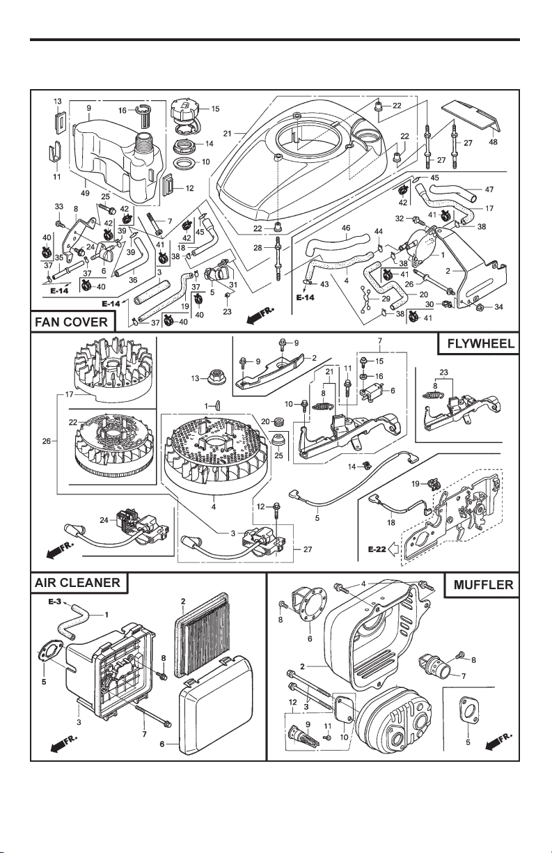
24
MODEL NUMBER GCV160-LAOS3B
HONDA 4-CYCLE ENGINE
9
HOW TO USE YOUR LAWN MOWER
ENGINE SPEED
Engine speed was set at the factory for
optimum performance. It is not adjustable.
ENGINE ZONE CONTROL
CAUTION: Federal regulations re quire
an engine control to be installed on this
lawn mower in order to minimize the risk
of blade contact injury. Do not un der
any circumstances attempt to de feat the
func tion of the operator con trol. The blade
turns when the engine is running.
• Your lawn mower is equipped with an
operator pres ence control bar which
requires the operator to be positioned
behind the lawn mower handle to start
and operate the lawn mower.
TO ADJUST CUTTING HEIGHT
Raise wheels for low cut and lower wheels
for high cut, adjust cutting height to suit
your requirements. Me di um position is
best for most lawns.
• To change cutting height, squeeze ad-
juster lever to ward wheel. Move wheel
up or down to suit your re quire ments.
Be sure all wheels are in the same set-
ting.
NOTE: Adjuster is properly positioned
when plate tab inserts into hole in lever.
Also, 9-position adjusters (if so equipped)
allow lever to be positioned between the
plate tabs.
Pivot pins Grass
catcher
handle
Catcher frame hook
Rear
door
SIDE DISCHARGING
• Rear door must be closed.
• Open mulcher door and install dis-
charge deflector under door as shown.
• Mower is now ready for discharging
operation.
• To convert to mulching or bagging
operation, dis charge deflector must be
removed and mulcher door must be
closed.
TO CONVERT MOWER
Your lawn mower was shipped ready to
be used as a mulcher. To convert to bag-
ging or discharging:
REAR BAGGING
• Lift rear door of the lawn mower and
place the grass catcher frame hooks
onto the door pivot pins.
• To convert to mulching or dis charg ing
operation, remove grass catch er and
close rear door.
LEVER BACKWARD TO
LOWER MOWER
LEVER FORWARD TO RAISE MOWER
Plate tab
Lever
Open mulcher door
Discharge deflector
The operation of any lawn mower can result in foreign objects
thrown into the eyes, which can result in severe eye damage.
Always wear safety glasses or eye shields while operating your
lawn mower or performing any adjustments or repairs. We recom-
mend standard safety glasses or a wide vision safety mask over spectacles.
Use ear
protec-
tors to
avoid
damage to hearing.
MOWER
IS NOW
READY FOR
DISCHARGING
OPERATION

8
IMPORTANT: This lawn mower is shipped
WITHOUT OIL OR GASOLINE in the engine.
NOTE: Gasoline containing up to 10% ethanol (E10) is acceptable for use in this machine.
The use of any gasoline exceeding 10% ethanol (E10) will void the product warranty.
OPERATION
KNOW YOUR LAWN MOWER
READ THIS OWNER'S MANUAL AND ALL SAFETY RULES BEFORE OPERATING YOUR
LAWN MOWER. Compare the illustrations with your lawn mower to familiarize yourself with
the location of various controls and adjustments. Save this manual for future reference.
Starter
handle
Housing
Wheel adjuster
(on each wheel)
Handle knob
Grass
catcher
Engine oil plug
Operator presence control bar
Fuel valve lever
MEETS CPSC SAFETY REQUIREMENTS
Sears rotary walk-behind power lawn mowers conform to the safety standards of the
American National Standards Institute and the U.S. Consumer Product Safety Com mis-
sion.
WARNING: The blade turns when the engine is running.
Operator presence control bar – must
be held down to the handle to start the
engine. Release to stop the engine.
These symbols may appear on your lawn mower or in literature supplied with the product.
Learn and understand their meaning.
Mulcher door – allows con ver sion to
discharging or bagging operation.
Starter handle – used for starting engine.
Muffler
Mulcher door
Air filter
Spark plug
Gasoline filler cap
25
FAN COVER
KEY PART
NO. NO. DESCRIPTION
6 16950-Z0Y-003 Petcock Assembly
7 16952-ZA8-800 Filter, Fuel
8 16961-Z0L-900 Stay, Fuel Petcock
9 17511-Z0L-030 Tank, Fuel
10 17514-Z0L-000 Seal, Fuel Filler Neck
11 17516-Z0L-000 Clip, Tank Mounting
12 17532-Z0L-000 Rubber A, Tank Mounting
13 17533-Z0L-000 Rubber B, Tank Mounting
14 17534-Z0L-000 Nut, Tank Mounting
15 17620-Z0J-800 Cap Assembly, Fuel Tank
16 17636-Z0L-000 Gauge, Fuel Level
21 19610-Z0L-861ZC Cover Assembly, Fan
“T89” (Craftsman Red)
19610-Z0L-861ZA Cover Assembly, Fan
“T89” (“NH1”) (Black)
19610-Z0L-861ZD Cover Assembly, Fan
“T93” (Husqvarna Grey)
19610-Z0L-861ZE Cover Assembly, Fan
“T98” (M.T.D. Red)
22 19619-ZL8-300 Collar, Fan Cover
24 90013-883-000 Bolt, Flanged (#6 x 12)
(CT200)
25 90015-883-000 Bolt, Flanged (#6 x 28)
(CT200)
27 90043-ZL8-000 Bolt, Stud (H=42.5mm)
28 90043-ZL8-000 Bolt, Stud (H=42.5mm)
33 93913-25220 Screw, Tapping (PO)
(#5 x 12)
35 91424-Z8B-821 Tube, Fuel Tank
36 91427-Z8B-821 Tube, Fuel (7.3 x 160)
40 95002-40800-08 Clip, Tube (D8)
42 95002-41200-08 Clip, Tube (D12)
MUFFLER
KEY PART
NO. NO. DESCRIPTION
1 18310-ZM0-000 Muffler
2 18321-Z0L-J00 Protector, Muffler
(S/N 1243452 and below)
18321-Z0L-J01 Protector, Muffler
(S/N 1243453 and above)
3 90004-ZL8-000 Bolt, Flange #6 x 79
(CT200)
4 90013-883-000 Bolt, Flange #6 x 12
(CT200)
5 18381-ZL8-305 Gasket, Muffler
9 18350-ZL8-000 Arrester, Spark
10 18356-ZL8-000 Plate, Arrester Number
11 90055-ZE1-000 Screw, Tapping #4 x 6
12 06180-Z0J-000 Kit, Spark Arrester
FLYWHEEL
KEY PART
NO. NO. DESCRIPTION
1 13331-357-000 Key, Special, Woodruff
(25 x 18)
3 30500-ZL8-014 Coil Assembly, Ignition
4 31105-ZM0-000 Flywheel Assembly
5 32195-ZM0-800 Wire, Stop Switch
6 35120-ZM0-003 Switch Assembly,
Engine Stop (NC)
8 75113-ZM0-000 Spring, Brake Lever
10 90014-952-000 Bolt, Flange (#6 x 14)
(CT200)
11 90018-ZE1-000 Bolt, Flange (#6 x 23)
(CT200)
12 90018-ZE1-000 Bolt, Flange (#6 x 23)
(CT200)
13 90201-Z0T-800 Nut, Special (14 mm)
14 51125-Z0L-003 Holder, Wire (Fastex)
90681-959-003 Clip A, Cable (3.8mm)
(Black) (NIFCO)
15 93892-04012-00 Screw, Washer Head
(#4 x 12)
16 94103-04000 Washer, Plain (4 mm)
21 75110-Z0Y-000 Brake Sub Assembly
25 91601-Z0L-300 Grommet, Brake Plate
AIR CLEANER
KEY PART
NO. NO. DESCRIPTION
1 15721-ZM0-000 Tube, Breather
2 17211-ZL8-023 Element, Air Cleaner
3 17220-ZM0-010 Case Assy., Air Cleaner
(S/N 1167575 and below)
17220-ZM0-020 Case Assy., Air Cleaner
(S/N 1167576–1239013)
17220-ZM0-030 Case Assy., Air Cleaner
(S/N 1239014 and above)
5 17228-ZM0-000 Gasket, Air Cleaner
6 17231-Z0L-030 Cover, Air Cleaner
(S/N 1167575 and below)
17231-Z0L-040 Cover, Air Cleaner
(S/N 1167575 and below)
17231-Z0L-050 Cover, Air Cleaner
7 90003-ZM0-010 Bolt, Flange (#6 x 85)
(CT200)
MODEL NUMBER GCV160-LAOS3B
HONDA 4-CYCLE ENGINE
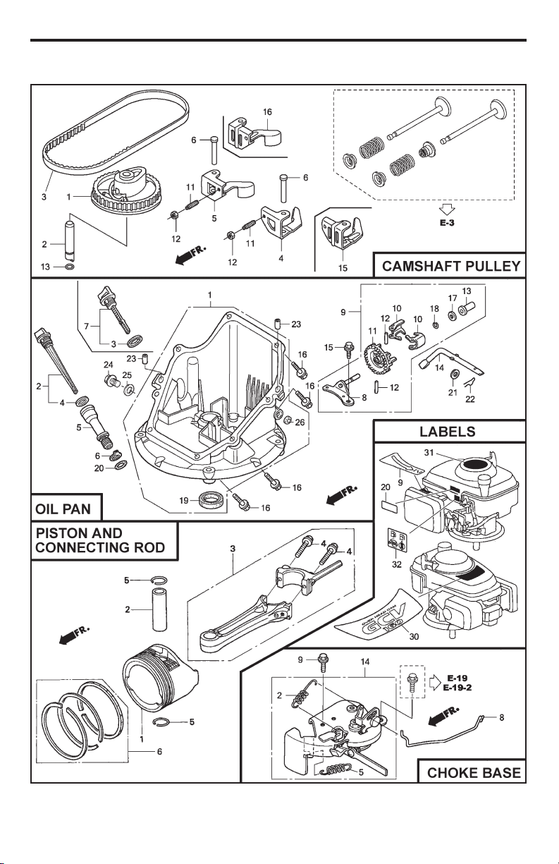
26
MODEL NUMBER GCV160-LAOS3B
HONDA 4-CYCLE ENGINE
7
TO ASSEMBLE GRASS CATCH ER
1. Put grass catcher frame into grass bag
with rigid part of bag on the bottom.
Make sure the frame handle is outside
of the bag top.
2. Slip vinyl bindings over frame.
NOTE: If vinyl bindings are too stiff, hold
them in warm water for a few minutes. If
bag gets wet, let it dry before using.
TO INSTALL ATTACHMENTS
Your lawn mower was shipped ready to
be used as a mulcher. To convert to bag-
ging, see “TO CON VERT MOW ER” in the
Operation section of this man u al.
Frame
handle
Frame
opening
Vinyl
bindings
INSTALL STARTER ROPE
1. Loosen T-knob.
2. Hold control bar against upper handle.
3. Slowly pull engine starter rope out until
rope will slip into loop of rope guide.
4. Tighten T-knob.
Upper handle
Control bar
Engine
starter rope
Rope guide
T-Knob

6
ASSEMBLY / PRE-OPERATION
Read these instructions and this manual
in its entirety before you attempt to as-
semble or operate your new lawn mower.
IMPORTANT: This lawn mower is
shipped WITHOUT OIL OR GASOLINE in
the engine.
Your new lawn mower has been as sem-
bled at the factory with the exception of
those parts left unassembled for shipping
purposes. All parts such as nuts, wash-
ers, bolts, etc., nec es sary to complete the
as sem bly have been placed in the parts
bag. To ensure safe and proper operation
of your lawn mower, all parts and hard-
ware you assemble must be tightened
securely. Use the correct tools as neces-
sary to ensure proper tightness.
TO REMOVE MOWER FROM
CAR TON
1. Remove loose parts included with
mower.
2. Cut down two end corners of carton
and lay end panel down flat.
3. Remove all packing materials except
padding between upper and lower
handle and padding holding operator
presence control bar to upper handle.
4. Roll mower out of carton and check
carton thor ough ly for additional loose
parts.
MOWING
POSITION
Lower handle
LIFT
UP
Operator
presence
control bar
Bolt
Nut
Bracket
Upper
handle
LIFT
UP
Handle
knob
HOW TO SET UP YOUR LAWN
MOW ER
TO UNFOLD HANDLE
IMPORTANT: Unfold handle carefully so
as not to pinch or damage con trol cables.
1. Raise handles until lower handle sec-
tion locks into place in mowing posi-
tion.
2. Insert bolt through handle and bracket
and secure with nut.
3. Remove protective padding, raise up-
per handle sec tion into place on lower
handle and tighten both handle knobs.
4. Remove handle padding holding
operator pres ence control bar to upper
handle.
Your lawn mower handle can be adjusted
for your mowing comfort. Refer to "AD-
JUST HANDLE" in the Service and Adjust-
ments section of this manual.
27
MODEL NUMBER GCV160-LAOS3B
HONDA 4-CYCLE ENGINE
CAMSHAFT PULLEY
KEY PART
NO. NO. DESCRIPTION
1 14320-ZL8-010 Pulley, Camshaft
2 14324-ZL8-000 Shaft, Cam Pulley
3 14400-Z0J-014 Belt, Timing
(84HU7 G-200)
6 14461-ZL8-000 Shaft, Rocker Arm
11 90112-333-000 Screw, Tappet Adjusting
12 90206-001-000 Nut, Tappet Adjusting
13 91301-ZM0-V31 O-Ring (6.8 x 1.9) (ARAI)
15 14431-Z0J-000 Rocker Arm, Intake Valve
16 14441-Z0J-000 Rocker Arm,
Exhaust Valve
OIL PAN
KEY PART
NO. NO. DESCRIPTION
1 11300-ZM0-811 Pan Assembly, Oil
2 15650-ZM0-801 Gauge Assembly,
Oil Level
4 15625-ZE6-000 Gasket, Oil Filler Cap
5 15631-ZM0-000 Extension, Oil Filler
6 15639-ZM0-000 Lock Washer, Extension
8 16508-ZM0-010 Shaft, Governor Holder
9 16510-ZM0-010 Governor Assembly
10 16511-ZL8-000 Weight, Governor
11 16512-ZM0-000 Holder, Governor Weight
12 16513-ZE1-000 Pin, Governor Weight
13 16531-ZE1-000 Slider, Governor
14 16541-ZM0-000 Shaft, Governor Arm
15 90014-952-000 Bolt, Flange (#6 x 14)
(CT200)
16 90121-952-000 Bolt, Flange (#6 x 25)
(CT200)
17 90451-ZE1-000 Washer, Thrust (6 mm)
18 90602-ZE1-000 Clip, Governor Holder
19 91202-ZL8-003 Oil Seal (28 x 41.25 x 6)
20 91356-MA6-005 O-Ring (14.8 x 2.4) (NOK)
21 94101-068000 Washer, Plain (6 mm)
22 94251-08000 Pin, Lock (8 mm)
23 94301-08200 Pin, Dowel (#8 x 20)
PISTON / CONNECTING ROD
KEY PART
NO. NO. DESCRIPTION
1 13101-Z2A-010 Piston
2 13111-ZE0-000 Pin, Piston
3 13200-Z0J-000 Connecting Rod Assem-
bly
4 90001-ZE1-000 Bolt, Connecting Rod
5 90551-ZE0-000 Clip, Piston Pin (13 mm)
6 13010-Z0L-014 Ring Set, Piston, Standard
(Teikoku)
LABELS
KEY PART
NO. NO. DESCRIPTION
9 87528-Z0L-V20 Mark, Choke Indication
20 87114-ZH7-821 Label, Warning
30 87101-Z8B-000 Mark, Emblem (GCV160)
31 87169-Z8E-000 Mark, Recoil Cover
32 87524-Z8B-000 Mark, Caution,
Fuel Petcock
CHOKE BASE
KEY PART
NO. NO. DESCRIPTION
2 16592-Z2D-800 Spring, Return
5 16614-Z2D-800 Spring, Choke Lever
8 16632-Z0L-801 Rod, Stop
9 90022-888-010 Bolt, Flange (#6 x 20)
(CT200)
14 16610-Z2D-801 Lever Assembly, Choke
16610-Z2D-802 Lever Assembly, Choke

28
EMISSION CONTROL SYSTEM WARRANTY
Your new Honda Power Equipment engine complies with the U.S. EPA, Environment Canada, and
State of California emission regulations (models certified for sale in California only). American Hon-
da Motor Co., Inc. provides the emission warranty coverage for engines in the United States and
its territories. Honda Canada Inc. provides the emission warranty for engines in the 13 provinces
and territories of Canada. In the remainder of this Emission Control System Warranty, American
Honda Motor Company Inc. and Honda Canada Inc. will be referred to as Honda.
YOUR WARRANTY RIGHTS AND OBLIGATIONS:
California
The California Air Resources Board and Honda are pleased to explain the emission control system
warranty on your Honda Power Equipment engine. In California, new spark-ignited small off-road
equipment engines must be designed, built, and equipped to meet the State's stringent anti-smog
standards.
Other States, U.S. territories, and Canada
In other areas of the United States and in Canada, your engine must be designed, built, and
equipped to meet the U.S. EPA and Environment Canada emission standards for spark-ignited en-
gines at or below 19 kilowatts. Specific Honda products that do not meet the California emissions
regulations can be identified by a “Not for sale in California” decal.
All of the United States and Canada
Honda must warrant the emission control system on your power equipment engine for the period
of time listed below, provided there has been no abuse, neglect, or improper maintenance of your
power equipment engine. Where a warrantable condition exists, Honda will repair your power
equipment engine at no cost to you including diagnosis, parts, and labor.
Your emission control system may include such parts as the carburetor or fuel injection system,
the ignition system, and catalytic converter. Also included may be hoses, connectors, and other
emission-related assemblies (see next page for additional covered parts).
OWNER'S WARRANTY RESPONSIBILITY:
As the power equipment engine owner, you are responsible for the performance of the required
maintenance listed in your owner's manual. Honda recommends that you retain all receipts covering
maintenance on your power equipment engine, but Honda cannot deny warranty coverage solely
for the lack of receipts or for your failure to ensure the performance of all scheduled maintenance.
As the power equipment engine owner, you should however be aware Honda may deny you
warranty coverage if your power equipment engine or a part has failed due to abuse, neglect,
improper maintenance, or unapproved modifications.
You are responsible for presenting your power equipment engine to a Honda Power Equipment
dealer as soon as a problem exists. The emission related warranty repairs should be completed
in a reasonable amount of time, not to exceed 30 days. If you have any questions regarding your
emission warranty rights and responsibilities, you should contact the Honda office in your region:
WARRANTY COVERAGE:
Honda power equipment engines sold in the United States and Canada are covered by this war-
ranty for a period of two years from the date of delivery to the original retail purchaser or the length
of the Honda Distributor’s Limited Warranty, whichever is longer. This warranty is transferable to
each subsequent purchaser for the duration of the warranty period.
If any emission-related part on your engine is defective, the part will be repaired or replaced by
Honda without charge for diagnosis, parts, or labor. All defective parts replaced under this warran-
ty become the property of Honda. A list of warranted parts is on the reverse side of this warranty
statement. Normal maintenance items, such as spark plugs and filters, that are on the warranted
parts list are warranted up to their required replacement interval only.
Honda will also replace other engine components damaged by a failure of any warranted part dur-
ing the warranty period.
American Honda Motor Co., Inc.
Power Equipment Customer Relations
4900 Marconi Drive
Alpharetta, Georgia 30005-8847
Telephone: (888) 888-3139
Email: [email protected]
or
Honda Canada Inc.
Power Equipment Customer Relations
Visit www.honda.ca
for contact information.
Telephone: (888) 946-6329
American Honda Motor Co., Inc. / Honda Canada Inc. 10/2009 00X51-ZG0-6110 PWL50975-M
5
LIST OF APPLICABLE WARRANTY PERIODS: The following list contains the applicable
Warranty Period for your Craftsman product and is based on a combination of the type
of product or component and the intended and actual use of the product or component:
1. 90 DAYS: Craftsman products intended for use or actually used for commercial,
institutional, professional or income-producing purposes
2. 2 YEARS: Craftsman riding lawn mowers, yard and garden tractors, walk behind
mowers, tillers, brush cutters, snow blowers, handheld blowers, backpack blowers,
hedge trimmers and electrical products for noncommercial, nonprofessional, non-
institutional, or non-income-producing use, except for those components which are
part of engine systems manufactured by third party engine manufacturers for which
the purchase has received an separate warranty with product information supplied
at the time of purchase.
3. 1 YEAR: Craftsman power cutters, stump grinders, pole pruners, gas chain saws,
electric chain saws, trimmer attachments, baggers and pole saws for noncommercial,
nonprofessional, non-institutional, or non-income-producing use.
4. 90 DAYS: All defective batteries, which will be replaced during this 90-day Warranty
Period.
5. 60 DAYS: Additional Warranty Period of 60 days will apply to adjustments and worn
products or components BUT DOES NOT INCLUDE WEAR OR ADJUSTMENTS
for products used for commercial, institutional, professional or income-producing
purposes. Wear items include but are not limited to: belts, blades, tires, spark plugs,
air filters, chains, shear bolts, skid plates, scraper bars, drift cutters, ropes, tines,
collection bags and pulleys.
As the Warranty Period runs from the date of purchase and NOT from the date that a
product is delivered, opened, assembled or first used, plea se ensure during this time
period that your product or component has been assembled and tested for correction
operation regardless of when you intend to actually use it. Claims made after the
Warranty Period has expired will not be honored.
PROOF OF PURCHASE/DOCUMENTATION: Warranty coverage is conditioned upon
the original purchaser furnishing Sears Canada or its authorized third party service
provider if applicable, with the original sales receipt or other adequate written proof
of the original purchase date and identification of the product. In the event that the
original purchaser is unable to provide a company of the original sales receipt, Sears
Canada Inc. reserves the right to determine in its sole discretion what other written
proof of the original purchase date and identification of the product is acceptable.
WARRANTY
Serial Number:
Date of Purchase:
Gasoline Capacity / Type: 1 Quart/0,94 Liters (Unleaded Regular)
Oil Capacity: 0,58 Quart/0,55 Liter
Oil Type (API SG–SL): SAE 30 (above 0°C/32°F) or SAE 10W-30
Spark Plug (Gap: 0,03"/0,76 mm) NGK BPR5ES
Valve Clearance (± 0.04 mm): Intake: 0.015 mm; Exhaust: 0.020 mm
Blade Bolt Torque: 35–40 ft. lbs. (47–54 Nm)
• The model and serial numbers will be found on a decal on the rear of the lawn mower
housing. Record both serial number and date of purchase in space provided above.
PRODUCT SPECIFICATIONS

4
WARRANTY
GENERAL: Craftsman products are warranted to be free from defects in materials
or workmanship for a specific time period as set-out below (the “Warranty Period”).
Warranties extend to the original purchaser of a Craftsman product only. Purchases
made through an online auction or through any website other than www.sears.ca are
excluded. The relevant Warranty Period commences on the original date of purchase.
Within this period, Sears Canada, Inc. will, at its sole option, repair or replace any
products or components which fail in normal use. Such repairs or replacement will be
made at no charge to the customer for parts or labor, provided that the customer shall be
responsible for any transportation cost.
EXCLUSIONS: This warranty does not cover failures due to normal wear, abuse, misuse,
neglect (including but not limited to the use of stale fuel, dirt, abrasives, moisture, rust,
corrosion, or any adverse reaction due to improper storage or use habits), improper
maintenance or failure to follow maintenance guidelines and/or instructions, failure to
operate the product in accordance with the owner’s manual or any additional instructions
or information provided at the time of purchase or in subsequent communications with
the original purchaser, accident or unauthorized alterations or repairs made or attempted
by others. Also excluded from warranty coverage – except as provided below - are
the following: maintenance, adjustments, components subject to wear including but
not limited to: cosmetic components, belts, blades, blade adapters, bulbs, tires, filters,
guide bars, lubricants, seats, grips, recoil assy’s, saw chains and bars, trimmer lines and
spools, spark plugs, starter ropers and tines, and discoloration resulting from ultraviolet
light. Any product missing the model and/or serial number identification label will be
disqualified from coverage under this warranty.
REPAIRS: Repairs have a 90 day warranty. If the defective product is still within the
Warranty Period, then the new warranty is 90 days from the date of repair or to the end of
the original Warranty Period, whichever period is longer.
DISCLAIMERS: THE WARRANTIES AND REMEDIES CONTAINED HEREIN ARE
EXCLUSIVE AND IN LIEU OF ALL OTHER WARRANTIES, WHETHER ORAL OR
WRITTEN (OTHER THAN AS STATED HEREIN), AND WHETHER EXPRESS, IMPLIED
OR STATUTORY, INCLUDING BUT NOT LIMITED TO ANY. THIS WARRANTY GIVES YOU
SPECIFIC LEGAL RIGHTS, WHICH MAY VARY FROM PROVINCE TO PROVINCE.
IN NO EVENT SHALL SEARS BE LIABLE FOR ANY INCIDENTAL, SPECIAL, INDIRECT
OR CONSEQUENTIAL DAMAGES, WHETHER RESULTING FROM THE USE, MISUSE
OR INABILITY TO USE THE PRODUCT OR FROM DEFECTS IN THE PRODUCT. THE
EXCLUSIONS IN THIS PARAGRAPH SHALL NOT APPLY IN JURISDICATIONS WHERE
APPLICABLE LAW DOES NOT ALLOW FOR THE EXCLUSION OF INCIDENTAL OR
CONSEQUENTIAL DAMAGES. IN SUCH JURISDICTIONS, THIS PARAGRAPH SHALL
NOT APPLY, BUT THE REMAINING PROVISIONS OF THIS DOCUMENT SHALL REMAIN
VALID.
Sears retains the exclusive right to repair or replace the product or offer a full refund of
the purchase price at its sole discretion. SUCH REMEDY SHALL BE YOUR SOLE AND
EXCLUSIVE REMEDY FOR ANY BREACH OF WARRANTY.
CUSTOMER RESPONSIBILITIES: In additional to complying with all suggested
maintenance guidelines and instructions, customers’ obligations shall include but shall
not be limited to: operating the product in accordance with the owner’s manual or any
additional instructions or information provided at the time of purchase or in subsequent
communications to the purchaser from time to time, exhibit reasonable care in the use,
operation, maintenance, general upkeep and storage of the product. Failure to comply
with these requirements will void any applicable warranty.
29
American Honda Motor Co., Inc.
Power Equipment Customer Relations
4900 Marconi Drive
Alpharetta, Georgia 30005-8847
Telephone: (888) 888-3139
Email: [email protected]
or
Honda Canada Inc.
Power Equipment Customer Relations
Visit www.honda.ca
for contact information.
Telephone: (888) 946-6329
Only Honda approved replacement parts may be used in the performance of any warranty repairs
and must be provided without charge to the owner. The use of replacement parts not equivalent
to the original parts may impair the effectiveness of your engine emission control system. If such
a replacement part is used in the repair or maintenance of your engine, and an authorized Honda
dealer determines it is defective or causes a failure of a warranted part, your claim for repair of
your engine may be denied. If the part in question is not related to the reason your engine requires
repair, your claim will not be denied.
TO OBTAIN WARRANTY SERVICE:
You must, at your own expense, take your Honda Power Equipment engine or the product on
which it is installed, along with your sales registration card or other proof of original purchase date,
to any Honda Power Equipment dealer who is authorized by Honda to sell and service that Honda
product during his normal business hours. Claims for repair or adjustment found to be caused
solely by defects in material or workmanship will not be denied because the engine was not prop-
erly maintained and used.
If you are unable to obtain emission warranty service or are dissatisfied with the warranty service
you received, contact the owner of the dealership involved. Normally this should resolve your
problem. However, if you require further assistance, contact the Honda office in your region:
American Honda Motor Co., Inc. / Honda Canada Inc. 10/2009 00X51-ZG0-6110 PWL50975-M
EXCLUSIONS:
Failures other than those resulting from defects in material or workmanship are not covered by this
warranty. This warranty does not extend to emission control systems or parts that are affected or dam-
aged by owner abuse, neglect, improper maintenance, misuse, misfueling, improper storage, colli-
sion, the incorporation of, or use of, unsuitable attachments, or the unauthorized alteration of any part.
This warranty does not cover replacement of expendable maintenance items made in connec-
tion with required maintenance service after the item’s first scheduled replacement as listed in the
maintenance section of the product owner’s manual, such as: spark plugs and filters.
Disclaimer of Consequential Damage and Limitation of Implied Warranties:
American Honda Motor Co., Inc. and Honda Canada Inc. disclaim any responsibility for inciden-
tal or consequential damages such as loss of time or the use of the power equipment, or any
commercial loss due to the failure of the equipment; and any implied warranties are limited to the
duration of this written warranty. This warranty is applicable only where the California, U.S. EPA, or
Environment Canada emission control system warranty regulation is in effect.
EMISSION CONTROL SYSTEM WARRANTY PARTS:
SYSTEMS PARTS
COVERED: DESCRIPTION:
Fuel Metering Carburetor Assembly (Includes Starting Enrichment System), Engine Temp-
erature Sensor, Engine Control Module, Fuel Regulator, Intake Manifold
Evaporative Fuel Tank, Fuel Cap, Fuel Hoses, Vapor Hoses, Carbon Canister, Canister
Mounting Brackets, Fuel Strainer, Fuel Cock, Fuel Pump, Fuel Hose Joint,
Canister Purge Hose Joint
Exhaust Catalyst, Exhaust Manifold
Air Induction Air Filter Housing, Air Filter Element*
Ignition Flywheel Magneto, Ignition Pulse Generator, Crankshaft Position Sensor, Power
Coil, Ignition Coil Assembly, Ignition Control Module, Spark Plug Cap, Spark Plug*
Crankcase Emission Control Crankcase Breather Tube, Oil Filler Cap
Misc. Items Tubing, Fittings, Seals, Gaskets & Clamps associated with these listed systems
Note: This list applies to parts supplied by Honda and does not cover parts supplied by the
equipment manufacturer. Please see the original equipment manufacturer’s emissions warranty for
non-Honda parts.
* Covered up to the first required replacement only.
See the Maintenance Schedule in the owner’s manual.

30
SERVICE NOTES
3
• Mow only in daylight or good artificial light.
• Do not operate the machine while under
the influence of alcohol or drugs.
• Never operate machine in wet grass.
Always be sure of your footing: keep a
firm hold on the handle; walk, never run.
• Disengage the drive system, if so equipped,
before starting the engine (motor).
• If the equipment should start to vi brate
abnormally, stop the engine (motor) and
check immediately for the cause. Vibra-
tion is generally a warning of trouble.
• Always wear eye protection when op er-
at ing machine.
• Use extra care when approaching blind
corners, shrubs, trees, or other objects
that may obscure vision.
• When loading or unloading this ma-
chine, do not exceed the maximum
recommended operation angle of 15°.
• Wear proper Personal Protective Equip-
ment (PPE) while operating this machine,
including (at a minimum) sturdy footwear,
eye protection, and hearing protection. Do
not mow in shorts or open toed footwear.
Always let someone know you are outside
mowing.
III. SLOPE OPERATION
Slopes are a major factor related to slip &
fall accidents, which can result in severe
injury. All slopes require extra caution. If
you feel uneasy on a slope, do not mow it.
DO:
• Mow across the face of slopes: nev er
up and down. Exercise extreme caution
when changing direction on slopes.
• Remove obstacles such as rocks, tree
limbs, etc.
• Watch for holes, ruts, bumps or hidden ob-
jects. Uneven terrain could cause a slip and
fall accident. Tall grass can hide obstacles.
DO NOT:
• Do not mow near drop-offs, ditches or
embankments. You could lose your foot-
ing or balance.
• Do not mow on wet grass or excessively
steep slopes. Poor footing could cause
a slip and fall accident.
IV. SAFE HANDLING OF GASOLINE
To avoid personal injury or property dam-
age, use extreme care in handling gaso-
line. Gasoline is extremely flammable and
the vapors are explosive.
• Extinguish all cigarettes, cigars, pipes
and other sources of ignition.
• Use only an approved container.
• Never remove gas cap or add fuel with
the engine running.
• Allow engine to cool before refueling.
• Never refuel the machine indoors.
• Never store the machine or fuel contain-
er where there is an open flame, spark
or pilot light such as a water heater or
on other appliances.
• Never fill containers inside a vehicle, on
a truck or trailer bed with a plastic liner.
Always place containers on the ground
away from your vehicle before filling.
• Remove gas-powered equipment from
the truck or trailer and refuel it on the
ground. If this is not possible, then
refuel such equipment with a portable
container, rather than from a gasoline
dispenser nozzle.
• Keep the nozzle in contact with the rim
of the fuel tank or container opening at
all times until fueling is complete. Do
not use a nozzle lock-open device.
• If fuel is spilled on clothing, change
clothing immediately.
• Never overfill fuel tank. Replace gas
cap and tighten securely.
V. GENERAL SERVICE
• Never run a machine inside a closed area.
• Never make adjustments or repairs with
the engine (motor) running. Dis con nect
the spark plug wire, and keep the wire
away from the plug to prevent ac ci den-
tal starting.
• Keep all nuts and bolts tight to be sure the
equipment is in safe working condition.
• Never tamper with safety devices.
Check their proper operation reg u lar ly.
Never do anything to interfere with the
intended function of a safety device or
reduce the protection provided by a
safety device.
• Keep machine free of grass, leaves, or
other debris build-up. Clean oil or fuel spill-
age. Allow machine to cool before storing.
• Stop and inspect the equipment if you
strike an object. Repair, if nec es sary,
before restarting.
• Never attempt to make wheel height
adjustments while the engine is running.
• Grass catcher components are sub ject
to wear, dam age, and de te ri o ra tion,
which could expose moving parts or
allow objects to be thrown. Frequently
check com po nents and replace with
man u fac tur er’s recommended parts,
when necessary.
• Mower blades are sharp and can cut.
Wrap the blade(s) or wear gloves, and
use extra caution when ser vic ing them.
• Do not change the engine governor set-
ting or overspeed the engine.
• Maintain or replace safety and instruc-
tion labels, as necessary.

2
Safety Rules .......................................... 2-3
Warranty - Lawn Mower ........................ 4-5
Product Spec i fi ca tions ........................... 5
Assembly/Pre-Operation ....................... 6-7
Operation ............................................ 8-11
Maintenance Schedule .......................... 12
Maintenance ...................................... 12-15
Service and Adjustments .................. 15-16
Storage .............................................. 16-17
Troubleshooting ................................ 18-19
Repair Parts ....................................... 20-27
Warranty - Honda Motor ................... 28-29
Sears Service ...........................Back Cover
TABLE OF CONTENTS
SAFETY RULES
IMPORTANT: This cutting machine is
capable of amputating hands and feet and
throwing objects. Failure to observe the
following safety instructions could result in
serious injury or death.
Look for this symbol to point out im por-
tant safety precautions. It means
CAU TION!!! BECOME ALERT!!!
YOUR SAFE TY IS INVOLVED.
WARNING: In order to prevent ac ci-
den tal starting when setting up, trans port-
ing, ad just ing or making repairs, always
dis con nect spark plug wire and place wire
where it can not come in contact with plug.
CAUTION: Muffler and other engine
parts become extremely
hot during operation and
remain hot after engine
has stopped. To avoid
severe burns on contact,
stay away from these areas.
I. CHILDREN
WARNING: CHILDREN CAN
BE SERIOUSLY INJURED OR
KILLED BY THIS EQUIPMENT.
Carefully read and follow all of
the safety instructions below.
The American Academy of Pediatrics
recommends that children be a minimum
of 12 year of age before operating a
pedestrian controlled lawn mower and a
minimum of 16 years of age before operat-
ing a riding lawn mower.
Tragic accidents can occur if the op er a tor is
not alert to the presence of children. Children
are often attracted to the ma chine and the
mowing activity. Never assume that children
will remain where you last saw them.
• Keep children out of the mowing area
and under the watchful care of a re-
spon si ble adult other than the operator.
• Be alert and turn machine off if chil dren
enter the area.
• Before and while walking back wards, look
behind and down for small chil dren.
• Never allow children to operate the
machine.
II. GENERAL OPERATION
• Read, understand, and follow all
in struc tions on the machine and in the
manual(s) before starting. Be thor ough ly
familiar with the controls and the proper
use of the machine before starting.
• Do not put hands or feet near or under
rotating parts. Keep clear of the dis-
charge opening at all times.
• Only allow responsible individuals, who
are familiar with the in struc tions, to
operate the machine.
• Clear the area of objects such as rocks,
toys, wire, bones, sticks, etc., which
could be picked up and thrown by
blade. Stay behind the handle when the
engine (motor) is running.
• Be sure the area is clear of other people
before mowing. Stop ma chine if anyone
enters the area.
• Do not operate machine bare footed or
while wearing sandals. Al ways wear
substantial footwear with good ankle
support while mowing.
• Do not pull mower backwards unless
absolutely nec es sary. Always look down
and behind before and while moving
backwards.
• Never direct discharged material toward
anyone. Avoid discharging material
against a wall or obstruction. Material may
richochet back toward the operator. Stop
blade when crossing gravel surfaces.
• Do not operate the mower without
proper guards, plates, grass catcher or
oth er safety protective devices in place.
• See manufacturer’s instructions for
proper operation and installation of
accessories. Only use accessories ap-
proved by the manufacturer.
• Stop the blade(s) when crossing grav el
drives, walks, or roads.
• Never leave a running machine unattended.
• Stop the engine (motor) and wait until the
blade comes to a complete stop before
clean ing the machine, removing the grass
catcher, or unclogging the discharge
chute.
31
SERVICE NOTES

02489
587785901 12.21.15 BY Printed in U.S.A.
Model No.
944.364152
CAUTION:
Read and follow all
Safety Rules and In struc tions
before operating this equipment
Owner’s Manual
ROTARY LAWN MOWER
160cc Honda Engine
21" Multi-Cut
Sears Canada, Inc., Toronto, Ontario M5B 2B8