587785602 Rev. 2 12.13.16 BY Printed in U.S.A.
Model No.
944.364702
CAUTION:
Read and follow all
Safety Rules and In struc tions
before operating this equipment
Owner’s Manual
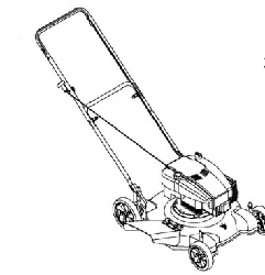
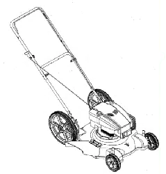
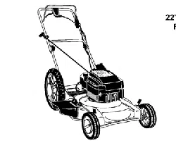
ROTARY LAWN MOWER
625 Series Briggs & Stratton Engine
Power-Propelled
22" Multi-Cut
Sears Canada, Inc., Toronto, Ontario M5B 2B8
2
TABLE OF CONTENTS
Safety Rules .......................................... 2-3
Warranty ................................................ 4-5
Product Spec i fi ca tions ........................... 5
Assembly/Pre-Operation ....................... 6-7
Operation ............................................ 8-12
Maintenance Schedule .......................... 13
Maintenance ...................................... 13-16
Service and Adjustments .................. 17-18
Storage .............................................. 18-19
Troubleshooting ................................ 20-21
Repair Parts ....................................... 22-31
Sears Service ...........................Back Cover
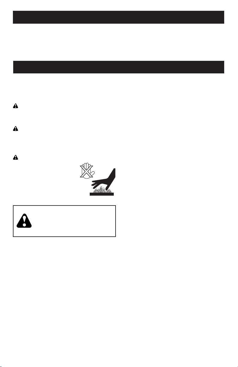
IMPORTANT: This cutting machine is
capable of amputating hands and feet and
throwing objects. Failure to observe the
following safety instructions could result in
serious injury or death.
Look for this symbol to point out im por-
tant safety precautions. It means
CAU TION!!! BECOME ALERT!!!
YOUR SAFE TY IS INVOLVED.
WARNING: In order to prevent ac ci-
den tal starting when setting up, trans port-
ing, ad just ing or making repairs, always
dis con nect spark plug wire and place wire
where it can not come in contact with plug.
CAUTION: Muffler and other engine
parts become extremely
hot during operation and
remain hot after engine
has stopped. To avoid
severe burns on contact,
stay away from these areas.
I. CHILDREN
WARNING: CHILDREN CAN
BE SERIOUSLY INJURED OR
KILLED BY THIS EQUIPMENT.
Carefully read and follow all of
the safety instructions below.
The American Academy of Pediatrics
recommends that children be a minimum
of 12 year of age before operating a
pedestrian controlled lawn mower and a
minimum of 16 years of age before operat-
ing a riding lawn mower.
Tragic accidents can occur if the op er a tor is
not alert to the presence of children. Children
are often attracted to the ma chine and the
mowing activity. Never assume that children
will remain where you last saw them.
• Keep children out of the mowing area
and under the watchful care of a re-
spon si ble adult other than the operator.
• Be alert and turn machine off if chil dren
enter the area.
• Before and while walking back wards,
look behind and down for small chil-
dren.
• Never allow children to operate the
machine.
II. GENERAL OPERATION
• Read, understand, and follow all
in struc tions on the machine and in the
manual(s) before starting. Be thor ough ly
familiar with the controls and the proper
use of the machine before starting.
• Do not put hands or feet near or under
rotating parts. Keep clear of the dis-
charge opening at all times.
• Only allow responsible individuals, who
are familiar with the in struc tions, to
operate the machine.
• Clear the area of objects such as rocks,
toys, wire, bones, sticks, etc., which
could be picked up and thrown by
blade. Stay behind the handle when the
engine (motor) is running.
• Be sure the area is clear of other people
before mowing. Stop ma chine if anyone
enters the area.
• Do not operate machine bare footed or
while wearing sandals. Al ways wear
substantial footwear with good ankle
support while mowing.
• Do not pull mower backwards unless
absolutely nec es sary. Always look down
and behind before and while moving
backwards.
• Never direct discharged material toward
anyone. Avoid discharging material
against a wall or obstruction. Material may
richochet back toward the operator. Stop
blade when crossing gravel surfaces.
• Do not operate the mower without
proper guards, plates, grass catcher or
oth er safety protective devices in place.
• See manufacturer’s instructions for
proper operation and installation of
accessories. Only use accessories ap-
proved by the manufacturer.
• Stop the blade(s) when crossing grav el
drives, walks, or roads.
• Never leave a running machine unattended.
• Stop the engine (motor) and wait until
the blade comes to a complete stop
before clean ing the machine, removing
the grass catcher, or unclogging the
discharge chute.
• Mow only in daylight or good artificial light.
SAFETY RULES
31
MODEL NUMBER 93J02-0098-F1
BRIGGS & STRATTON 4-CYCLE ENGINE
KEY PART
NO. NO. DESCRIPTION
404 690272 Washer (Governor Crank)
445 593260 Filter-Air Cleaner Cartridge
455 593960 Cup-Flywheel
493 593330 Bracket-Mounting
(Carburetor)
505 793515 Nut (Governor Control Lever)
523 796503 Dipstick
524 691876 Seal-Dipstick Tube
562 793514 Bolt
(Governor Control Lever)
598 592587 Shim-End Play (Crankshaft)
(Used After Date Code
15100100)
593291 Shim-End Play (Crankshaft)
(Used Before Date Code
15100200)
601 791850 Clamp-Hose (Green)
608 593959 Starter-Rewind
613 590562 Screw (Muffler)
615 690340 Retainer-Governor Shaft
616 590516 Crank-Governor
617 270344s Seal-O Ring (Intake Manifold)
621 692310 Switch-Stop
623 799581 Seal-O Ring
(Carburetor Spacer)
635 692076 Boot-Spark Plug
668 590546 Spacer (Flywheel)
718 690959 Pin-Locating
724 697478 Retainer-Seal
729 594752 Clip-Wire
741 594105 Gear-Timing
745 691146 Screw (Brake) (#10-32 x .8)
745A 690859 Screw (Brake) (#10-32 x .5)
770 595355 Kit-Rewind/Blower Housing
830 590536 Stud-Rocker Arm
836 690661 Screw (Muffler Guard)
(#8-18 x .4)
842 691031 Seal-O Ring (Dipstick)
847 590572 Dipstick/Tube Assembly
KEY PART
NO. NO. DESCRIPTION
850 100106 Sealant-Silicone
868 590534 Seal-Valve
875 595661 Base-Air Cleaner
914 591103 Screw (Rocker Cover)
922 692135 Spring-Brake
923 691487 Brake
951 591104 Lever-Choke
957 591003 Cap-Fuel
968 595658 Cover-Air Cleaner
971 590552 Screw (Air Cleaner Base
to Carburetor)
972 590568 Fuel-Tank
975 594632 Bowl-Float
1022 595341 Gasket-Rocker Cover
1023 590513 Cover-Rocker
1026 590515 Rod-Push
(Intake and Exhaust)
1029 590526 Arm-Rocker (Exhaust)
1029A 590527 Arm-Rocker (Intake)
1036 - - - Label-Emissions (Available
From A Briggs & Stratton
Authorized Dealer)
1127 590554 Screw (Float Bowl
to Carburetor Body)
1238 590562 Screw (Carburetor Spacer)
(M5 x 17mm)
1263 697124 Reed-Breather
1264 793453 Screw (Breather Reed)
1329 N/A Replacement Engine
1330 N/A Repair Manual
- - 398067 Spark Arrester
(available accessory)
Carburetor Overhaul Kit Key No. 121
Engine Gasket Set Key No. 358
NOTE: All component dimensions given in U.S.
inches. 1 inch = 25.4 mm

30
KEY PART
NO. NO. DESCRIPTION
1 592359 Cylinder Assembly
3 299819s Kit-Bushing / Seal
(Magneto Side)
4 594101 Sump-Engine
5 592641 Head-Cylinder
7 592358 Gasket-Cylinder Head
11 590522 Tube-Breather
12 799587 Gasket-Crankcase
13 590512 Screw (Cylinder Head)
16 595024 Crankshaft
20 391781s Seal-Oil (PTO Side)
22 692551 Screw (Crankcase Cover /
Sump) (1/4-20 x 1.1)
22A 590763 Screw (Crankcase Cover /
Sump) (1/4-20 x .78)
23 590544 Flywheel
24 222698s Key-Flywheel (Aluminum)
25 592360 Piston Assembly (Standard)
26 592660 Ring Set (Standard)
27 691588 Lock-Piston Pin
28 298909 Pin-Piston (Used After
Date Code 15100100)
699659 Pin-Piston Pin (Used Before
Date Code 15100200)
29 594089 Rod-Connecting (Used After
Date Code 15100100)
590518 Rod-Connecting (Used
Before Date Code 15100200)
32 691664 Screw (Connecting Rod)
33 590531 Valve-Exhaust
34 590530 Valve-Intake
35 590532 Spring-Valve (Intake)
36 590532 Spring-Valve (Exhaust)
37 594729 Guard-Flywheel
40 590528 Retainer-Valve
43 697799 Slinger-Governor/Oil
45 590514 Tappet-Valve
46 592968 Camshaft
48 N/A Short Block
KEY PART
NO. NO. DESCRIPTION
58 591108 Rope-Starter
60 281434s Grip-Starter Rope
78 793480 Screw (Flywheel Guard)
(M5 x 14mm)
104 590558 Pin-Float Hinge
117 592805 Jet-Main (Standard)
118 592690 Jet-Main (High Altitude)
(5000 > 9000 Feet)
121 590589 Kit-Carburetor Overhaul
122 590549 Spacer-Carburetor
125 592361 Carburetor
133 591120 Float-Carburetor
137 594633 Seal-O Ring (Float Bowl)
137A 593235 Seal-O Ring (Float Bowl)
155 590529 Plate-Cylinder Head
163 799580 Gasket-Air Cleaner
187 791766 Line-Fuel
(Cut To Required Length)
188 793480 Screw (Control Bracket)
(M5 x 14mm)
192 590535 Adjuster-Rocker Arm
202 590517 Link-Mechanical Governor
209 590541 Spring-Governor (Purple)
216 590547 Link-Choke
217 590740 Spring-Choke Return
222 590560 Bracket-Control
227 590520 Lever-Governor Control
238 590533 Cap-Valve
300 595516 Muffler
304 593961 Housing-Blower
305 590586 Screw (Blower Housing)
318 793480 Screw (Mounting Bracket)
332 690662 Nut (Flywheel)
333 593872 Armature-Magneto
334 691061 Screw (Magneto Armature)
(#8-32 x .9)
337 591039 Plug-Spark
356 692390 Wire-Stop
358 595350 Gasket Set-Engine
MODEL NUMBER 93J02-0098-F1
BRIGGS & STRATTON 4-CYCLE ENGINE
3
• Do not operate the machine while under
the influence of alcohol or drugs.
• Never operate machine in wet grass.
Always be sure of your footing: keep a
firm hold on the handle; walk, never run.
• Disengage the drive system, if so equipped,
before starting the engine (motor).
• If the equipment should start to vi brate
abnormally, stop the engine (motor) and
check immediately for the cause. Vibra-
tion is generally a warning of trouble.
• Always wear eye protection when op er-
at ing machine.
• Use extra care when approaching blind
corners, shrubs, trees, or other objects
that may obscure vision.
• When loading or unloading this ma-
chine, do not exceed the maximum
recommended operation angle of 15°.
• Wear proper Personal Protective Equip-
ment (PPE) while operating this ma-
chine, including (at a minimum) sturdy
footwear, eye protection, and hearing
protection. Do not mow in shorts or
open toed footwear.
Always let someone know you are outside
mowing.
III. SLOPE OPERATION
Slopes are a major factor related to slip &
fall accidents, which can result in severe
injury. All slopes require extra caution. If
you feel uneasy on a slope, do not mow it.
DO:
• Mow across the face of slopes: nev er
up and down. Exercise extreme caution
when changing direction on slopes.
• Remove obstacles such as rocks, tree
limbs, etc.
• Watch for holes, ruts, bumps or hidden
objects. Uneven terrain could cause a
slip and fall accident. Tall grass can hide
obstacles.
DO NOT:
• Do not mow near drop-offs, ditches or
embankments. You could lose your foot-
ing or balance.
• Do not mow on wet grass or excessively
steep slopes. Poor footing could cause
a slip and fall accident.
IV. SAFE HANDLING OF GASOLINE
To avoid personal injury or property dam-
age, use extreme care in handling gaso-
line. Gasoline is extremely flammable and
the vapors are explosive.
• Extinguish all cigarettes, cigars, pipes
and other sources of ignition.
• Use only an approved container.
• Never remove gas cap or add fuel with
the engine running.
• Allow engine to cool before refueling.
• Never refuel the machine indoors.
• Never store the machine or fuel contain-
er where there is an open flame, spark
or pilot light such as a water heater or
on other appliances.
• Never fill containers inside a vehicle, on
a truck or trailer bed with a plastic liner.
Always place containers on the ground
away from your vehicle before filling.
• Remove gas-powered equipment from
the truck or trailer and refuel it on the
ground. If this is not possible, then
refuel such equipment with a portable
container, rather than from a gasoline
dispenser nozzle.
• Keep the nozzle in contact with the rim
of the fuel tank or container opening at
all times until fueling is complete. Do
not use a nozzle lock-open device.
• If fuel is spilled on clothing, change
clothing immediately.
• Never overfill fuel tank. Replace gas
cap and tighten securely.
V. GENERAL SERVICE
• Never run a machine inside a closed area.
• Never make adjustments or repairs with
the engine (motor) running. Dis con nect the
spark plug wire, and keep the wire away
from the plug to prevent ac ci den tal starting.
• Keep all nuts and bolts tight to be sure the
equipment is in safe working condition.
• Never tamper with safety devices.
Check their proper operation reg u lar ly.
Never do anything to interfere with the
intended function of a safety device or
reduce the protection provided by a
safety device.
• Keep machine free of grass, leaves, or
other debris build-up. Clean oil or fuel spill-
age. Allow machine to cool before storing.
• Stop and inspect the equipment if you
strike an object. Repair, if nec es sary,
before restarting.
• Never attempt to make wheel height
adjustments while the engine is running.
• Grass catcher components are sub ject
to wear, dam age, and de te ri o ra tion,
which could expose moving parts or
allow objects to be thrown. Frequently
check com po nents and replace with
man u fac tur er’s recommended parts,
when necessary.
• Mower blades are sharp and can cut.
Wrap the blade(s) or wear gloves, and
use extra caution when ser vic ing them.
• Do not change the engine governor set-
ting or overspeed the engine.
• Maintain or replace safety and instruc-
tion labels, as necessary.

4
WARRANTY
GENERAL: Craftsman products are warranted to be free from defects in materials
or workmanship for a specific time period as set-out below (the “Warranty Period”).
Warranties extend to the original purchaser of a Craftsman product only. Purchases
made through an online auction or through any website other than www.sears.ca are
excluded. The relevant Warranty Period commences on the original date of purchase.
Within this period, Sears Canada, Inc. will, at its sole option, repair or replace any
products or components which fail in normal use. Such repairs or replacement will be
made at no charge to the customer for parts or labor, provided that the customer shall be
responsible for any transportation cost.
EXCLUSIONS: This warranty does not cover failures due to normal wear, abuse, misuse,
neglect (including but not limited to the use of stale fuel, dirt, abrasives, moisture, rust,
corrosion, or any adverse reaction due to improper storage or use habits), improper
maintenance or failure to follow maintenance guidelines and/or instructions, failure to
operate the product in accordance with the owner’s manual or any additional instructions
or information provided at the time of purchase or in subsequent communications with
the original purchaser, accident or unauthorized alterations or repairs made or attempted
by others. Also excluded from warranty coverage – except as provided below - are
the following: maintenance, adjustments, components subject to wear including but
not limited to: cosmetic components, belts, blades, blade adapters, bulbs, tires, filters,
guide bars, lubricants, seats, grips, recoil assy’s, saw chains and bars, trimmer lines and
spools, spark plugs, starter ropers and tines, and discoloration resulting from ultraviolet
light. Any product missing the model and/or serial number identification label will be
disqualified from coverage under this warranty.
REPAIRS: Repairs have a 90 day warranty. If the defective product is still within the
Warranty Period, then the new warranty is 90 days from the date of repair or to the end of
the original Warranty Period, whichever period is longer.
DISCLAIMERS: THE WARRANTIES AND REMEDIES CONTAINED HEREIN ARE
EXCLUSIVE AND IN LIEU OF ALL OTHER WARRANTIES, WHETHER ORAL OR
WRITTEN (OTHER THAN AS STATED HEREIN), AND WHETHER EXPRESS, IMPLIED
OR STATUTORY, INCLUDING BUT NOT LIMITED TO ANY. THIS WARRANTY GIVES YOU
SPECIFIC LEGAL RIGHTS, WHICH MAY VARY FROM PROVINCE TO PROVINCE.
IN NO EVENT SHALL SEARS BE LIABLE FOR ANY INCIDENTAL, SPECIAL, INDIRECT
OR CONSEQUENTIAL DAMAGES, WHETHER RESULTING FROM THE USE, MISUSE
OR INABILITY TO USE THE PRODUCT OR FROM DEFECTS IN THE PRODUCT. THE
EXCLUSIONS IN THIS PARAGRAPH SHALL NOT APPLY IN JURISDICATIONS WHERE
APPLICABLE LAW DOES NOT ALLOW FOR THE EXCLUSION OF INCIDENTAL OR
CONSEQUENTIAL DAMAGES. IN SUCH JURISDICTIONS, THIS PARAGRAPH SHALL
NOT APPLY, BUT THE REMAINING PROVISIONS OF THIS DOCUMENT SHALL REMAIN
VALID.
Sears retains the exclusive right to repair or replace the product or offer a full refund of
the purchase price at its sole discretion. SUCH REMEDY SHALL BE YOUR SOLE AND
EXCLUSIVE REMEDY FOR ANY BREACH OF WARRANTY.
CUSTOMER RESPONSIBILITIES: In additional to complying with all suggested
maintenance guidelines and instructions, customers’ obligations shall include but shall
not be limited to: operating the product in accordance with the owner’s manual or any
additional instructions or information provided at the time of purchase or in subsequent
communications to the purchaser from time to time, exhibit reasonable care in the use,
operation, maintenance, general upkeep and storage of the product. Failure to comply
with these requirements will void any applicable warranty.
29
MODEL NUMBER 93J02-0098-F1
BRIGGS & STRATTON 4-CYCLE ENGINE
Engine Power Rating Information
The gross power rating for individual gas engine models is labeled in accordance with SAE
(Society of Automotive Engineers) code J1940 (Small Engine Power & Torque Rating Procedure),
and rating performance has been obtained and corrected in accordance with SAE J1995 (Revision
2002-05). Torque values are derived at 3060 RPM; horsepower values are derived at 3600 RPM.
Actual gross engine power will be lower and is affected by, among other things, ambient operat-
ing conditions and engine-to-engine variability. Given both the wide array of products on which
engines are placed and the variety of environmental issues applicable to operating the equipment,
the gas engine will not develop the rated gross power when used in a given piece of power equip-
ment (actual “on-site” or net power). This difference is due to a variety of factors including, but not
limited to, accessories (air cleaner, exhaust, charging, cooling, carburetor, fuel pump, etc.), ap-
plication limitations, ambient operating conditions (temperature, humidity, altitude), and engine-to-
engine variability. Due to manufacturing and capacity limitations, Briggs & Stratton may substitute
an engine of higher rated power for this Series engine.
850
7
358
1472
868
163
623
12
3
20
163
121
104
617
623
217
1022
105
137A
1218
202
188
222
209
334
333
337
635

28
MODEL NUMBER 93J02-0098-F1
BRIGGS & STRATTON 4-CYCLE ENGINE
13
1026
1029
45
238
36
35
155
33
34
40
5
868
1029A
192
40
163
623
1022
914
1022
1023
7
830
850
337
635
445
875
968
11
971
163
505
616
562
615
227
404
46
43
745
745A
621
922
923
5
LIST OF APPLICABLE WARRANTY PERIODS: The following list contains the applicable
Warranty Period for your Craftsman product and is based on a combination of the type
of product or component and the intended and actual use of the product or component:
1. 90 DAYS: Craftsman products intended for use or actually used for commercial,
institutional, professional or income-producing purposes
2. 2 YEARS: Craftsman riding lawn mowers, yard and garden tractors, walk behind
mowers, tillers, brush cutters, snow blowers, handheld blowers, backpack blowers,
hedge trimmers and electrical products for noncommercial, nonprofessional, non-
institutional, or non-income-producing use, except for those components which are
part of engine systems manufactured by third party engine manufacturers for which
the purchase has received an separate warranty with product information supplied
at the time of purchase.
3. 1 YEAR: Craftsman power cutters, stump grinders, pole pruners, gas chain saws,
electric chain saws, trimmer attachments, baggers and pole saws for noncommercial,
nonprofessional, non-institutional, or non-income-producing use.
4. 90 DAYS: All defective batteries, which will be replaced during this 90-day Warranty
Period.
5. 60 DAYS: Additional Warranty Period of 60 days will apply to adjustments and worn
products or components BUT DOES NOT INCLUDE WEAR OR ADJUSTMENTS
for products used for commercial, institutional, professional or income-producing
purposes. Wear items include but are not limited to: belts, blades, tires, spark plugs,
air filters, chains, shear bolts, skid plates, scraper bars, drift cutters, ropes, tines,
collection bags and pulleys.
As the Warranty Period runs from the date of purchase and NOT from the date that a
product is delivered, opened, assembled or first used, plea se ensure during this time
period that your product or component has been assembled and tested for correction
operation regardless of when you intend to actually use it. Claims made after the
Warranty Period has expired will not be honored.
PROOF OF PURCHASE/DOCUMENTATION: Warranty coverage is conditioned upon
the original purchaser furnishing Sears Canada or its authorized third party service
provider if applicable, with the original sales receipt or other adequate written proof
of the original purchase date and identification of the product. In the event that the
original purchaser is unable to provide a company of the original sales receipt, Sears
Canada Inc. reserves the right to determine in its sole discretion what other written
proof of the original purchase date and identification of the product is acceptable.
WARRANTY
Serial Number:
Date of Purchase:
Gasoline Capacity / Type: 0,75 Litres (Unleaded Regular)
Oil Capacity: 0,42 Litres
Oil Type (API SJ–SN): SAE 30 (above 0°C/32°F); SAE 5W-30 (below 0°C/32°F)
Spark Plug: Champion RC12YC (Gap: 0,5 mm)
Blade Bolt Torque: 35–40 ft. lbs. (47–54 Nm)
• The model and serial numbers will be found on a decal on the rear of the lawn mower
housing. Record both serial number and date of purchase in space provided above.
PRODUCT SPECIFICATIONS
6
Read these instructions and this manual
in its entirety before you attempt to as-
semble or operate your new lawn mower.
IMPORTANT: This lawn mower is shipped
WITHOUT OIL OR GASOLINE in the
engine.
Your new lawn mower has been as sem bled
at the factory with the exception of those
parts left unassembled for shipping pur-
pos es. To ensure safe and proper op er a tion
of your lawn mower, all parts and hard ware
you assemble must be tight ened securely.
Use the correct tools as nec es sary to en-
sure proper tightness. All parts such as
nuts, wash ers, bolts, etc., nec es sary to
complete the as sem bly have been placed
in the parts bag.
TO REMOVE MOWER FROM
CARTON
1. Remove loose parts included with
mower.
2. Cut down two end corners of carton
and lay end panel down flat.
3. Remove all packing materials except
padding be tween upper and lower
handle and padding holding operator
presence control bar to upper handle.
4. Roll lawn mower out of carton and
check carton thor ough ly for additional
loose parts.
ASSEMBLY / PRE-OPERATION
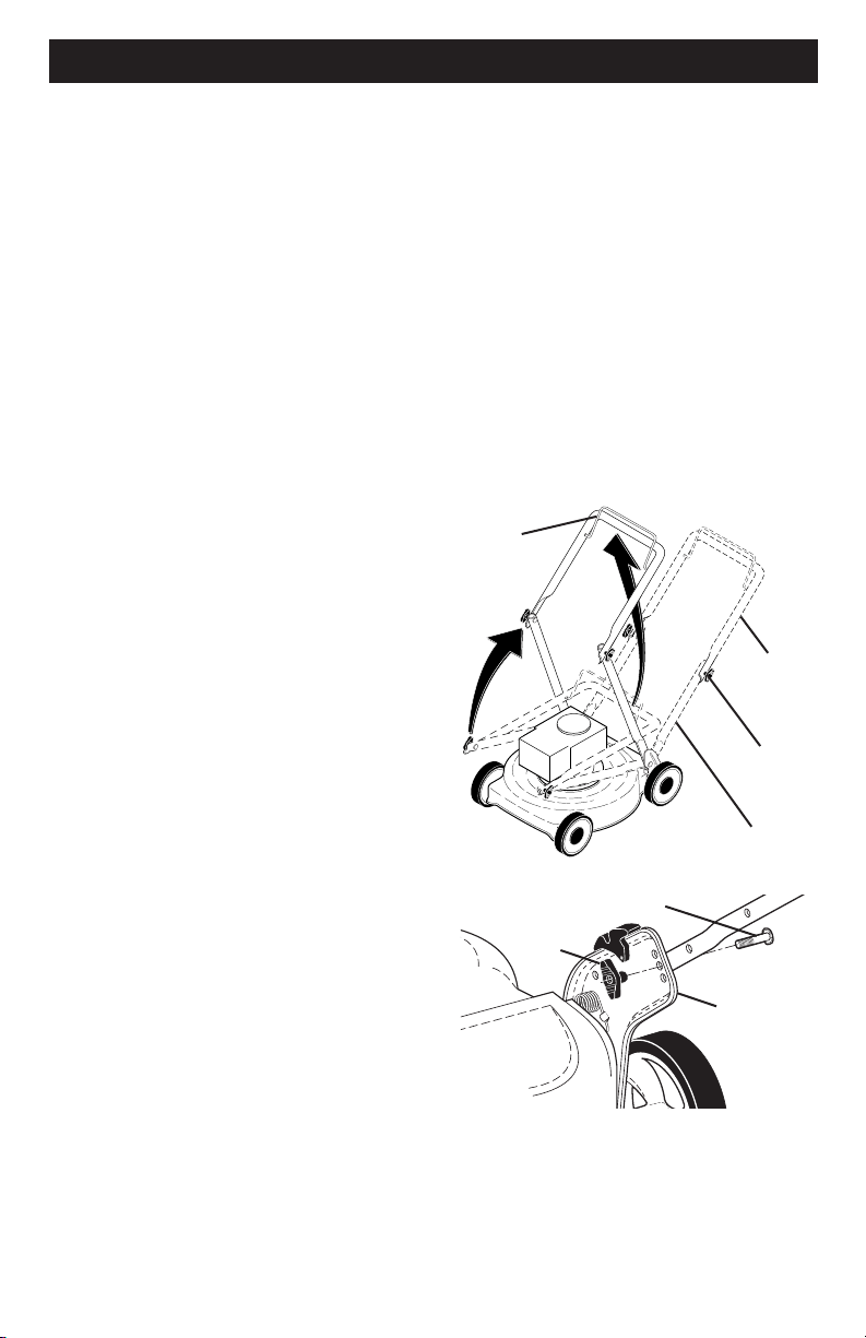
Handle
bracket
Knob
Bolt
MOWING
POSITION
Lower handle
LIFT
UP
Operator
presence
control bar
Upper
handle
LIFT
UP
Handle
knob
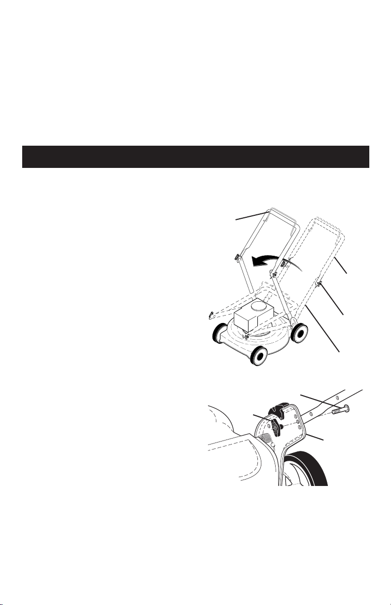
HOW TO SET UP YOUR MOW ER
TO UNFOLD HANDLE
IMPORTANT: Unfold handle carefully so
as not to pinch or damage con trol cables.
1. Raise handles until lower handle sec-
tion locks into place in mowing posi-
tion.
2. Remove protective padding, raise up-
per handle sec tion into place on lower
handle and tighten both handle knobs.
3. Remove handle padding holding
operator pres ence control bar to upper
handle.
Your lawn mower handle can be adjusted
for your mowing comfort. Refer to “AD-
JUST HANDLE” in the Service and Adjust-
ments section of this manual.
27
MODEL NUMBER 93J02-0098-F1
BRIGGS & STRATTON 4-CYCLE ENGINE
163
125
133
975
1127
617
104
217
623
724
117
118
623
493
1238
951
122
216
601
187
957
972
318
105
729
137
300
613
836
26
MODEL NUMBER 93J02-0098-F1
BRIGGS & STRATTON 4-CYCLE ENGINE
24
26
718
27
1
3
25
28
16
20
12
4
1264
1263
22
718
22A
741
32
29
27
850
598
332
668
48
133013291036
524
842
847
523
356
60
770
58
23
455
332
668
78
37
24
608
304
305
7
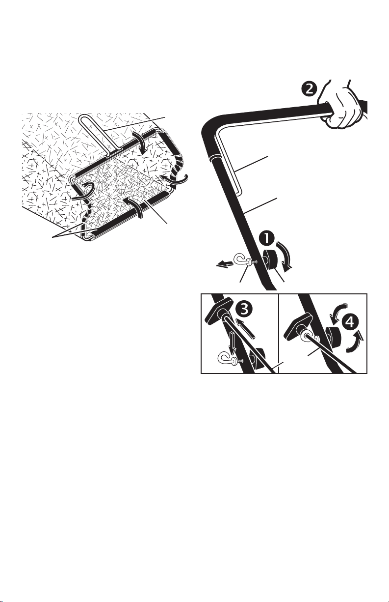
TO ASSEMBLE GRASS CATCH ER
1. Put grass catcher frame into grass bag
with rigid part of bag on the bottom.
Make sure the frame handle is outside
of the bag top.
2. Slip vinyl bindings over frame.
NOTE: If vinyl bindings are too stiff, hold
them in warm water for a few minutes. If
bag gets wet, let it dry before using.
Frame
opening
Vinyl
bindings
Frame
handle
INSTALL STARTER ROPE
1. Loosen T-knob.
2. Hold control bar against upper handle.
3. Slowly pull engine starter rope out until
rope will slip into loop of rope guide.
4. Tighten T-knob.
Upper handle
Control bar
Engine
starter rope
Rope guide
T-Knob
TO INSTALL ATTACHMENTS
Your lawn mower was shipped ready to
be used as a mulcher. To convert mower
to bagging or discharging, see “TO CON-
VERT MOWER” in the Operation section
of this manual.
8
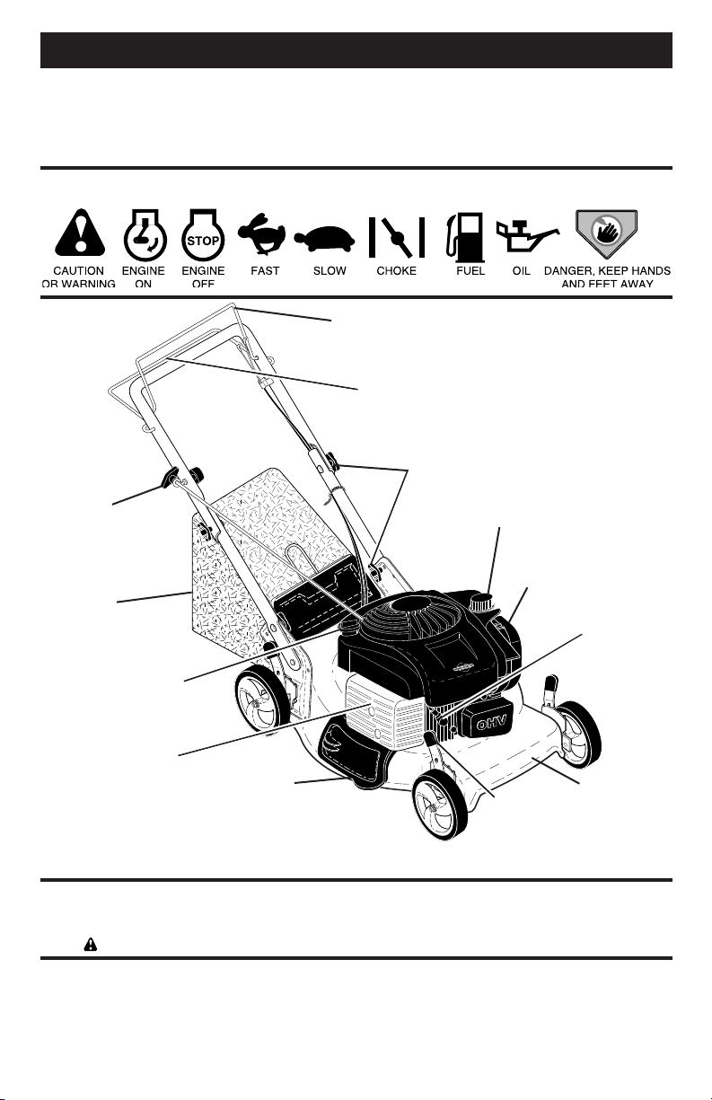
KNOW YOUR LAWN MOWER
READ THIS OWNER'S MANUAL AND ALL SAFETY RULES BEFORE OP ER AT ING YOUR
LAWN MOWER. Compare the illustrations with your lawn mower to familiarize yourself
with the location of various controls and adjustments. Save this manual for future refer-
ence.
These symbols may appear on your lawn mower or in literature supplied with the
product. Learn and understand their meaning.
OPERATION
Wheel adjuster
(on each wheel)
Operator presence control bar
Handle knobs
MEETS CPSC SAFETY REQUIREMENTS
Sears rotary walk-behind power lawn mowers conform to the safety standards of the
American National Standards Institute and the U.S. Consumer Product Safety Com mis-
sion.
WARNING: The blade turns when the engine is running.
Operator presence control bar – must
be held down to the handle to start the
engine. Release to stop the engine.
Primer– pumps additional fuel from the
carburetor to the cylinder for use when
starting a cold engine.
Starter handle – used for starting engine.
Drive control bar – used to engage pow-
er-pro pelled forward mo tion of mower.
Mulcher door – allows con ver sion to
discharging or bagging operation.
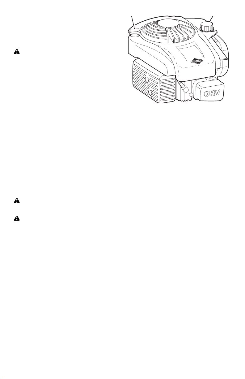
Grass
catcher
Drive control bar
Engine oil cap
with dipstick
Air filter
Gasoline filler cap
Housing
Mulcher door
Starter
handle
Spark
plug
IMPORTANT: This lawn mower is shipped
WITHOUT OIL OR GASOLINE in the engine.
NOTE: Gasoline containing up to 10% ethanol (E10) is acceptable for use in this machine.
The use of any gasoline exceeding 10% ethanol (E10) will void the product warranty.
Muffler
25
CRAFTSMAN ROTARY LAWN MOWER - - MODEL NUMBER 944.364702
NOTE: All component dimensions given in U.S. inches. 1 inch = 25.4 mm.
IMPORTANT: Use only Original Equipment Manufacturer (O.E.M.) replacement parts. Failure to do so could be hazardous, damage your lawn mower and void your warranty.
KEY PART
NO. NO. DESCRIPTION
KEY PART
NO. NO. DESCRIPTION
1 586033302 Drive Control Assembly
(Includes Cable)
4 197480 O-Ring
7 194185X428 Control Bar, Drive
12 580364604 Belt, Drive
13 581680801 Gear Case Assembly, Complete
14 586963001 Pulley, Drive
15 581497908 Wheel Adjuster, Rear, RH
16 581497907 Wheel Adjuster, Rear, LH
18 701037 Selector Knob
20 580806901 Debris Shield
22 17000510 Screw, Hex Head 5/16-18
25 581313802 Mounting Bracket, Debris Shield
26 589318301 Bracket, Gearcase
27 67725 Washer
28 12000058 E-Ring 7/16
29 581840401 Cover, Dust, Wheel
30 191730 Nut, Hex
31 404845 Pawl, Drive
32 581685301 Wheel & Tire Assembly, Rear
33 409148 Nut, Flangelock 3/8-16
34 404835 Pinion
35 431138 Wheel Adjuster, Front, RH
36 431139 Wheel Adjuster, Front, LH
37 163409 Screw, Hi-Lo Thread
40 400246X460 Wheel & Tire Assembly, Front
55 581351301 Spring, Return
59 441786X004 Support Bracket
86 587969201 Pulley, Idler
87 581127601 Screw
24
CRAFTSMAN ROTARY LAWN MOWER - - MODEL NUMBER 944.364702
33
40
12
13
14
15
16
18
26
27
4
27
4
28
28
29
29
30
30
30
31
31
34
34
35
36
37
55
18
18
18
22
22
59
59
20
25
22
86
87
32
32
33
33
33
40
1
7
9
HOW TO USE YOUR LAWN MOWER
ENGINE SPEED
Engine speed was set at the factory for
optimum performance. It is not adjustable.
ENGINE ZONE CONTROL
CAUTION: Federal regulations re quire
an engine control to be installed on this
lawn mower in order to minimize the risk
of blade contact injury. Do not un der
any circumstances attempt to de feat the
func tion of the operator con trol. The blade
turns when the engine is running.
• Your lawn mower is equipped with an
operator pres ence control bar which
requires the operator to be positioned
behind the lawn mower handle to start
and operate the lawn mower.
TO OPERATE DRIVE SYSTEM
• To start forward motion, lift drive con-
trol bar up to handle.
• To stop forward motion, release drive
control bar.
IMPORTANT: Always keep drive control
fully engaged against handle when in use.
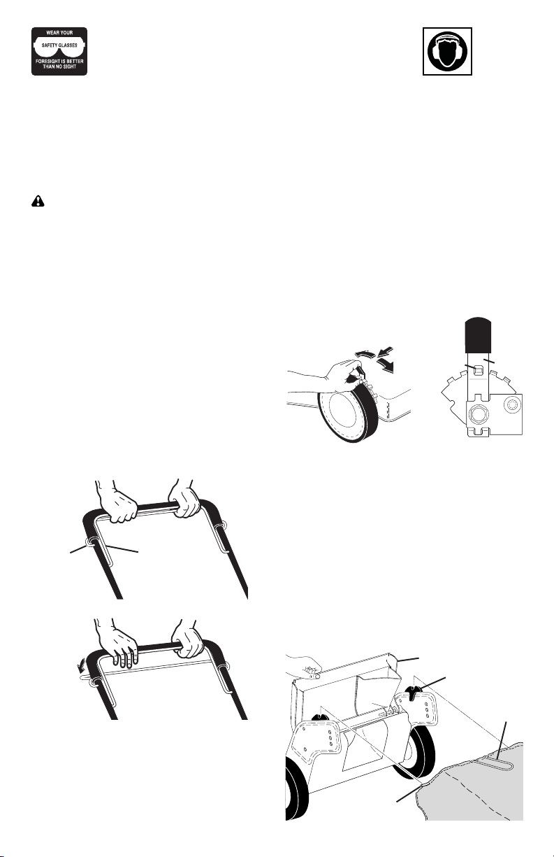
TO ADJUST CUTTING HEIGHT
Raise wheels for low cut and lower wheels
for high cut, adjust cutting height to suit
your requirements. Me di um position is
best for most lawns.
• To change cutting height, squeeze ad-
juster lever to ward wheel. Move wheel
up or down to suit your re quire ments.
Be sure all wheels are in the same set-
ting.
NOTE: Adjuster is properly positioned
when plate tab inserts into hole in lever.
Also, 9-position adjusters (if so equipped)
allow lever to be positioned between the
plate tabs.
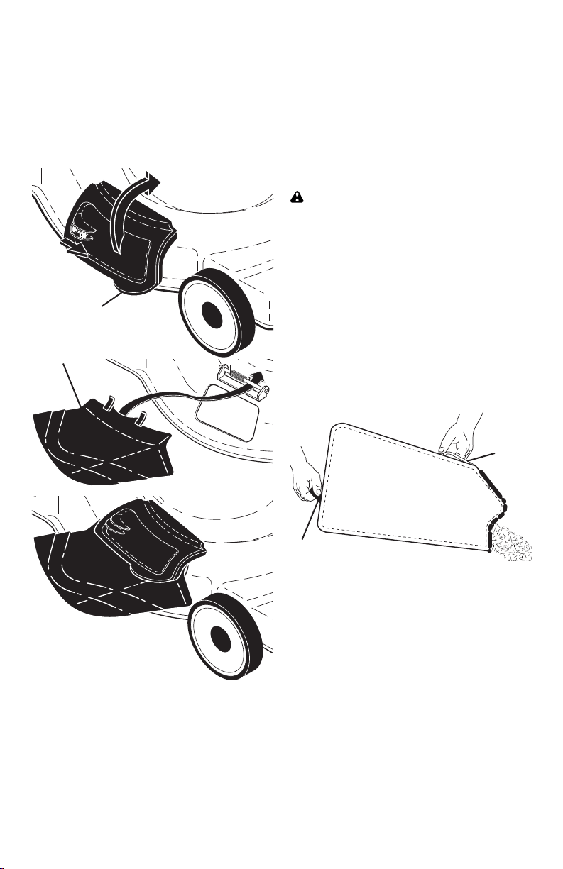
TO CONVERT MOWER
Your lawn mower was shipped ready to
be used as a mulcher. To convert to bag-
ging or discharging:
REAR BAGGING
• Lift rear door of the lawn mower and
place the grass catcher frame hooks
onto the grass bag brackets.
• To convert to mulching or dis charg ing
operation, remove grass catch er and
close rear door.
Grass bag
bracket
Grass
catcher
handle
Grass catcher
frame hook
Rear door
DRIVE CONTROL ENGAGED
Operator
pres ence
con trol bar
DRIVE CONTROL DIS EN GAGED
Drive
con trol
bar
ROTATE LEVER TOWARD
ENGINE TO LOWER MOWER
ROTATE LEVER AWAY FROM ENGINE
TO RAISE MOWER
Plate tab Lever
The operation of any lawn mower can result in foreign objects
thrown into the eyes, which can result in severe eye damage.
Always wear safety glasses or eye shields while operating your
lawn mower or performing any adjustments or repairs. We recom-
mend standard safety glasses or a wide vision safety mask over spectacles.
Use ear
protec-
tors to
avoid
damage to hearing.
10
SIMPLE STEPS TO
REMEMBER WHEN
CONVERTING YOUR LAWN MOWER
FOR MULCHING -
1. Rear door closed.
2. Mulcher door closed and locked.
FOR REAR BAGGING -
1. Grass catcher installed.
2. Mulcher door closed and locked.
FOR SIDE DISCHARGING -
1. Rear door closed.
2. Discharge deflector installed.
CAUTION: Do not run your lawn mow-
er with out rear door closed or ap proved
grass catcher in place. Never at tempt to
op er ate the lawn mow er with the rear door
re moved or propped open.
TO EMPTY GRASS CATCHER
1. Lift up on grass catcher using the
frame han dle.
2. Remove grass catcher with clippings
from under lawn mower han dle.
3. Empty clippings from bag using both
frame handle and bag handle.
NOTE: Do not drag the bag when empty-
ing; it will cause unnecessary wear.
Unlock
latch
Discharge
deflector
Open
mulcher door
SIDE DISCHARGING
• Rear door must be closed.
• Open mulcher door and install dis-
charge deflector under door as shown.
• Mower is now ready for discharging
operation.
• To convert to mulching or bagging
operation, dis charge deflector must be
removed and mulcher door must be
closed and locked.
MOWER IS NOW READY
FOR DISCHARGING
OPERATION
Grass
catcher
frame
handle
Bag
handle
23
CRAFTSMAN ROTARY LAWN MOWER - - MODEL NUMBER 944.364702
NOTE: All component dimensions given in U.S. inches. 1 inch = 25.4 mm.
IMPORTANT: Use only Original Equipment Manufacturer (O.E.M.) replacement parts. Failure to do so could be hazardous, damage your lawn mower and void your warranty.
30 580947303 Grassbag
31 585054703 Frame, Grass Catcher
32 419944X007 Latch, Mulcher Door
33 432642 Mulcher Door
34 419946X615 Bracket, Grassbag
36 175735 Hinge Bracket Assembly
38 419942X428 Discharge Deflector
39 585900702 Handle Bracket, LH
40 585900802 Handle Bracket, RH
41 150406 Screw, Dogpoint
3/8-16 x 1-1/8
42 193000 Spring, Torsion
43 191730 Nut, Hex, Nylock
44 586601602 Kit, Lawn Mower Housing
45 175650 Rod, Hinge
46 585481201 Blade Adapter / Pulley
47 421825 Blade, 22"
48 851074 Washer, Hardened
49 850263 Washer, Helical
50 851084 Screw, Machine, Hex Head
3/8-24 x 1-3/8 Grade 8
KEY PART
NO. NO. DESCRIPTION
1 585864805 Upper Handle Assembly
2 440385 Cable, Engine Zone Control
3 429930X004 Bracket, Upstop
6 189713X428 Handle Knob
7 178848 Screw, Hex Washer Head
#10-16 x 5/8
8 427612X428 Control Bar
9 585847601 Rear Door Assembly
11 425575 Hairpin, Door/Handle Pivot
13 437516 Plug, Handle Bar
17 581782101 Rear Baffle
18 581912601 T-Knob
19 581902101 Rope Guide
20 444501 Rear Skirt
21 419949 Spring, Rear Door, LH, Black
22 141841 Screw, Panhead, Torx #20
24 419948 Spring, Rear Door, RH, Grey
26 419945 Screw, Rear Door /
Handle Pivot
28 586212501 Bolt, Carriage 5/16-18 x 5/8
KEY PART
NO. NO. DESCRIPTION
51 430599 Front Baffle
52 182166 Decal, Danger
53 17000510 Screw
56 17411312 Screw, Hex Washer Head
#13 x 3/4
57 155377 Nut, Hex
58 585908202 Lower Handle
59 191574 Handle Bolt
64 - - - Engine, Briggs & Stratton,
Model Number 93J02-
0098-F1 (See Breakdown)
83 750097 Screw, Hex Washer Head
84 428124 Fastener, Push
85 429801X004 Mounting Bracket, Skirt
96 197991 Clip, Cable
97 581115302 Bracket
- - 423849 Bag of Parts (Includes
Key Numbers 12 and 59)
- - 587785602 Owner’s Manual, English
- - 587785603 Owner's Manual, French
KEY PART
NO. NO. DESCRIPTION
22
CRAFTSMAN ROTARY LAWN MOWER - - MODEL NUMBER 944.364702
REPAIR PARTS
1
3
7
8
9
21
30
31
32
33
36
53
38
39
42
44
45
46
47
48
49
50
51
52
53
57
22
34
53
57
28
28
22
34
40
41
41
43
53
97
59
13
11
17
26
56
56
58
59
11
26
59
24
20
83
85
2
6
6
6
6
84
96
18
19
64
56
84
11
TO STOP ENGINE
• To stop engine, release operator pres-
ence con trol bar.
TO START ENGINE
NOTE: Due to protective coatings on the
engine, a small amount of smoke may be
present during the initial use of the prod-
uct and should be considered normal.
NOTE: Your engine is equipped with an
automatic choke system. No priming or
choking is required before starting.
• To start engine, hold operator presence
control bar down to the han dle and
pull starter handle quickly. Do not allow
starter rope to snap back.
BEFORE STARTING ENGINE
ADD OIL
Your lawnmower is shipped without oil in
the engine. For type and grade of oil to
use, see “EN GINE” in the Maintenance
section of this manual.
CAUTION: DO NOT overfill engine with
oil, or it will smoke heavily from the muffler
on startup.
1. Be sure lawnmower is level.
2. Remove oil dipstick from oil fill spout.
3. You receive a container of oil with the
unit. Slowly pour the entire container
down the oil fill spout into the engine.
NOTE: Initial oil fill requires only 18 oz.
due to residual oil in engine from the
manufacturers 100% quality testing. When
changing oil you may need 20 oz.
4. Insert and tighten dipstick.
IMPORTANT:
• Check oil level before each use. Add
oil if needed. Fill to full line on dipstick.
ADD GASOLINE
• Fill fuel tank to bottom of tank filler
neck. Do not overfill. Use fresh, clean,
regular unleaded gasoline with a mini-
mum of 87 octane. Do not mix oil with
gasoline. Purchase fuel in quan ti ties
that can be used within 30 days to as-
sure fuel freshness.
CAUTION: Wipe off any spilled oil or
fuel. Do not store, spill or use gasoline
near an open flame.
CAUTION: Alcohol blended fuels
(called gasohol or using ethanol or meth-
anol) can attract moisture which leads to
separation and for ma tion of acids during
storage. Acidic gas can damage the fuel
system of an engine while in storage. To
avoid engine problems, the fuel system
should be emptied before stor age of 30
days or longer. Empty the gas tank, start
the engine and let it run until the fuel lines
and carburetor are empty. Use fresh fuel
next season. See Storage In struc tions for
additional information. Never use engine
or carburetor cleaner products in the fuel
tank or permanent damage may occur.
Engine oil cap Gasoline filler
cap
12
MULCHING MOWING TIPS
IMPORTANT: For best performance,
keep mower housing free of built-up
grass and trash. See “CLEANING” in the
Maintenance section of this manual.
• The special mulching blade will recut
the grass clip pings many times and
reduce them in size so that as they fall
onto the lawn they will disperse into
the grass and not be noticed. Also,
the mulched grass will bio de grade
quick ly to provide nu tri ents for the lawn.
Always mulch with your highest engine
(blade) speed as this will provide the
best recutting action of the blades.
• Avoid cutting your lawn when it is wet.
Wet grass tends to form clumps and
in ter feres with the mulch ing action. The
best time to mow your lawn is the early
afternoon. At this time the grass has
dried, yet the newly cut area will not be
exposed to direct sunlight.
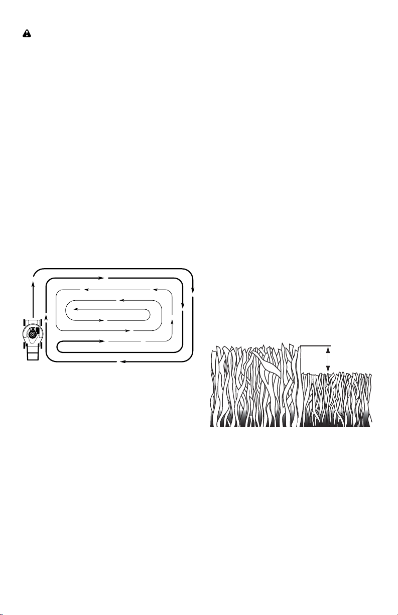
• For best results, adjust the lawn mower
cutting height so that the lawn mower
cuts off only the top one-third of the
grass blades. If the lawn is over grown
it will be nec es sary to raise the height
of cut to reduce pushing effort and to
keep from over load ing the engine and
leaving clumps of mulched grass. For
ex tremely heavy grass, reduce your
width of cut by overlapping previously
cut path and mow slowly.
• Certain types of grass and grass
con di tions may re quire that an area be
mulched a second time to com pletely
hide the clip pings. When doing a sec-
ond cut, mow across (perpendicular) to
the first cut path.
• Change your cutting pattern from week
to week. Mow north to south one week
then change to east to west the next
week. This will help prevent matting
and graining of the lawn.
MAX 1/3
MOWING TIPS
CAUTION: Do not use de-thatcher
blade attachments on your mower. Such
attachments are hazardous, will damage
your mower and could void your warranty.
• Under certain conditions, such as very
tall grass, it may be necessary to raise
the height of cut to reduce pushing
effort and to keep from over load ing the
en gine and leaving clumps of grass
clippings. It may also be necessary to
reduce ground speed and/or run the
lawn mower over the area a second
time.
• For extremely heavy cutting, reduce the
width of cut by overlapping pre vi ous ly
cut path and mow slowly.
• For side discharge operation, cut in
a coun ter clock wise di rec tion, start ing
at the outside of the area to be cut, in
order to spread grass clip pings more
evenly and to put less load on the
engine. To keep clip pings off of walk-
ways, flower beds, etc., make the first
cuts in a clock wise direction.
• If a trail of grass clipping is left on the
right side of the lawn mower during rear
discharge operation, mow in a clock-
wise direction with a small overlap to
collect the clippings on the next pass.
• Pores in cloth grass catchers can be-
come filled with dirt and dust with use
and catchers will collect less grass. To
prevent this, regularly hose catcher off
with water and let dry before using.
• Keep top of engine around starter clear
and clean of grass clippings and chaff.
This will help engine air flow and extend
engine life.
21
Loss of power 1. Rear of lawn mower 1. Raise cutting height.
housing or cutting blade
dragging in heavy grass.
2. Cutting too much grass. 2. Raise cutting height.
3. Dirty air filter. 3. Clean/replace air filter.
4. Buildup of grass, leaves, 4. Clean underside of mower
and trash under mower. housing.
5. Too much oil in engine. 5. Check oil level.
6. Walking speed too fast. 6. Cut at slower walking speed.
Poor cut – 1. Worn, bent or loose blade. 1. Replace blade. Tighten
uneven blade bolt.
2. Wheel heights uneven. 2. Set all wheels at same
height.
3. Buildup of grass, leaves 3. Clean underside of
and trash under mower. mower housing.
Excessive 1. Worn, bent or loose blade. 1. Replace blade. Tighten
vibration blade bolt.
2. Bent engine crankshaft. 2. Contact a Sears or other
qualified service centre.
Starter rope 1. Engine flywheel brake is on 1. Depress control bar to
hard to pull when control bar is released. upper handle before
pulling starter rope.
2. Bent engine crankshaft. 2. Contact a Sears or other
qualified service centre.
3. Blade adapter broken. 3. Replace blade adapter.
4. Blade dragging in grass. 4. Move lawn mower to cut
grass or to hard surface.
Grass catcher 1. Cutting height too low. 1. Raise cutting height.
not filling 2. Lift on blade worn off. 2. Replace blade.
(If so equipped) 3. Catcher not venting air. 3. Clean grass catcher.
Hard to push 1. Grass is too high or wheel 1. Raise cutting height.
height is too low.
2. Rear of lawn mower 2. Raise rear of lawn mower
housing or cutting blade housing one (1) setting
dragging in grass. higher.
3. Grass catcher too full. 3. Empty grass catcher.
4. Handle height position not 4. Adjust handle height to suit.
right for you.
Loss of drive 1. Belt wear. 1. Check/replace drive belt.
or slowing of 2. Belt off of pulley. 2. Check/reinstall drive belt.
drive speed 3. Drive cable worn or broken. 3. Replace drive cable.
4. “Loose” drive control system. 4. Adjust drive control.
PROBLEM CAUSE CORRECTION
TROUBLESHOOTING - See appropriate section in manual unless directed
to a Sears Parts & Repair Centre.
20
Does not start 1. Dirty air filter. 1. Clean/replace air filter.
2. Out of fuel. 2. Fill fuel tank.
3. Stale fuel. 3. Empty fuel tank and refill tank
with fresh, clean gasoline.
4. Water in fuel. 4. Empty fuel tank and refill tank
with fresh, clean gasoline.
5. Spark plug wire is 5. Connect wire to plug.
disconnected.
6. Bad spark plug. 6. Replace spark plug.
7. Loose blade or broken 7. Tighten blade bolt or
blade adapter. replace blade adapter.
8. Control bar in released 8. Depress control bar to
position. handle.
9. Control bar defective. 9. Replace control bar.
10. Fuel valve lever (if so 10. Turn fuel valve lever
equipped) in OFF position. to the ON position.
11. Weak battery (if equipped). 11. Charge battery.
12. Disconnected battery 12. Connect battery to engine.
connector (if equipped).
13. Blown fuse (if equipped). 13. Replace fuse.
PROBLEM CAUSE CORRECTION
TROUBLESHOOTING - See appropriate section in manual unless directed
to a Sears Parts & Repair Centre.
13
MAINTENANCE
GENERAL REC OM MEN DA TIONS
The warranty on this lawn mower does not
cover items that have been sub ject ed to
operator abuse or negligence. To receive
full value from the warranty, operator must
maintain unit as in struct ed in this manual.
Some adjustments will need to be made
periodically to properly maintain your unit.
At least once a season, check to see if
you should make any of the adjustments
described in the Service and Ad just ments
section of this manual.
• At least once a year, replace the spark
plug, clean or replace air filter element
and check blade for wear. A new spark
plug and clean/new air filter element
assure proper air-fuel mix ture and help
your engine run bet ter and last longer.
• Follow the maintenance schedule in this
manual.
BEFORE EACH USE
• Check engine oil level.
• Check for loose fasteners.
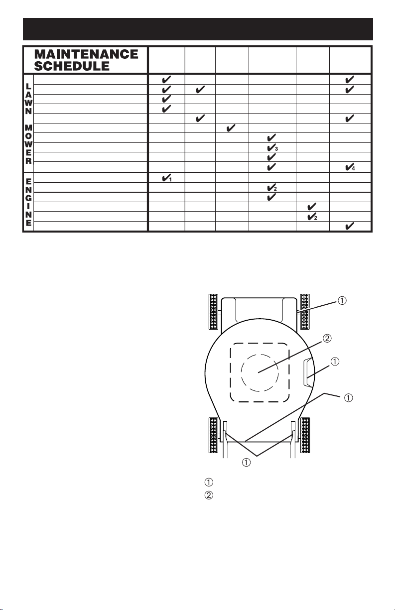
LUBRICATION
Keep unit well lubricated
(See “LU BRI CA TION CHART”).
LUBRICATION CHART
Spray lubricant
See "ENGINE" in Maintenance section.
Wheel
adjuster (on
each wheel)
Engine oil
Rear
door hinge
Handle bracket mounting pins
Mulcher
door hinge
pin
IMPORTANT: Do not oil or grease plastic
wheel bearings. Viscous lu bri cants will
attract dust and dirt that will short en the life
of the self-lu bri cat ing bearings. If you feel
they must be lu bri cated, use only a dry,
pow dered graphite type lubricant spar ingly.
Check for Loose Fasteners
Clean / Inspect Grass Catcher *
Check Tires
Check Drive Wheels ***
Clean Lawn Mower ****
Clean under Drive Cover ***
Check Drive Belt / Pulleys ***
Check / Sharpen / Replace Blade
Lubrication
Clean and Recharge Battery **
Check Engine Oil level
Clean Air Filter
Inspect Muffler
Replace Spark Plug
Replace Air Filter Paper Cartridge
Empty fuel system or add Stabilizer
BEFORE
EACH
USE
AFTER
EACH
USE
EVERY
10
HOURS
EVERY
25 HOURS
OR SEASON
EVERY
100
HOURS
BEFORE
STORAGE
(if so equipped)
Electric-Start mowers
Power-Propelled mowers
Use a scraper to clean under deck
*
**
***
****
1 - And after each 5 hours of use.
2 - Service more often if operating in dirty or dusty conditions.
3 - Replace blades more often when mowing in sandy soil.
4 - Charge 48 hours at end of season.
14
LAWN MOWER
Always observe safety rules when per-
form ing any main te nance.
TIRES
• Keep tires free of gasoline, oil, or insect
control chemi cals which can harm rubber.
• Avoid stumps, stones, deep ruts, sharp
objects and other hazards that may
cause tire damage.
DRIVE WHEELS
Check rear drive wheels each time you
mow to be sure they move freely. The
wheels not turning freely means trash,
grass cuttings, etc., may be inside the
drive wheel and dust cover area and must
be cleaned out to free drive wheels.
If necessary to clean the drive wheels,
check both rear wheels.
BLADE CARE
For best results, mower blade must be
kept sharp. Re place a bent or dam aged
blade.
CAUTION: Use only a replacement
blade approved by the manufacturer of
your mower. Using a blade not approved
by the manufacturer of your mower is
hazardous, could damage your mower
and void your warranty.
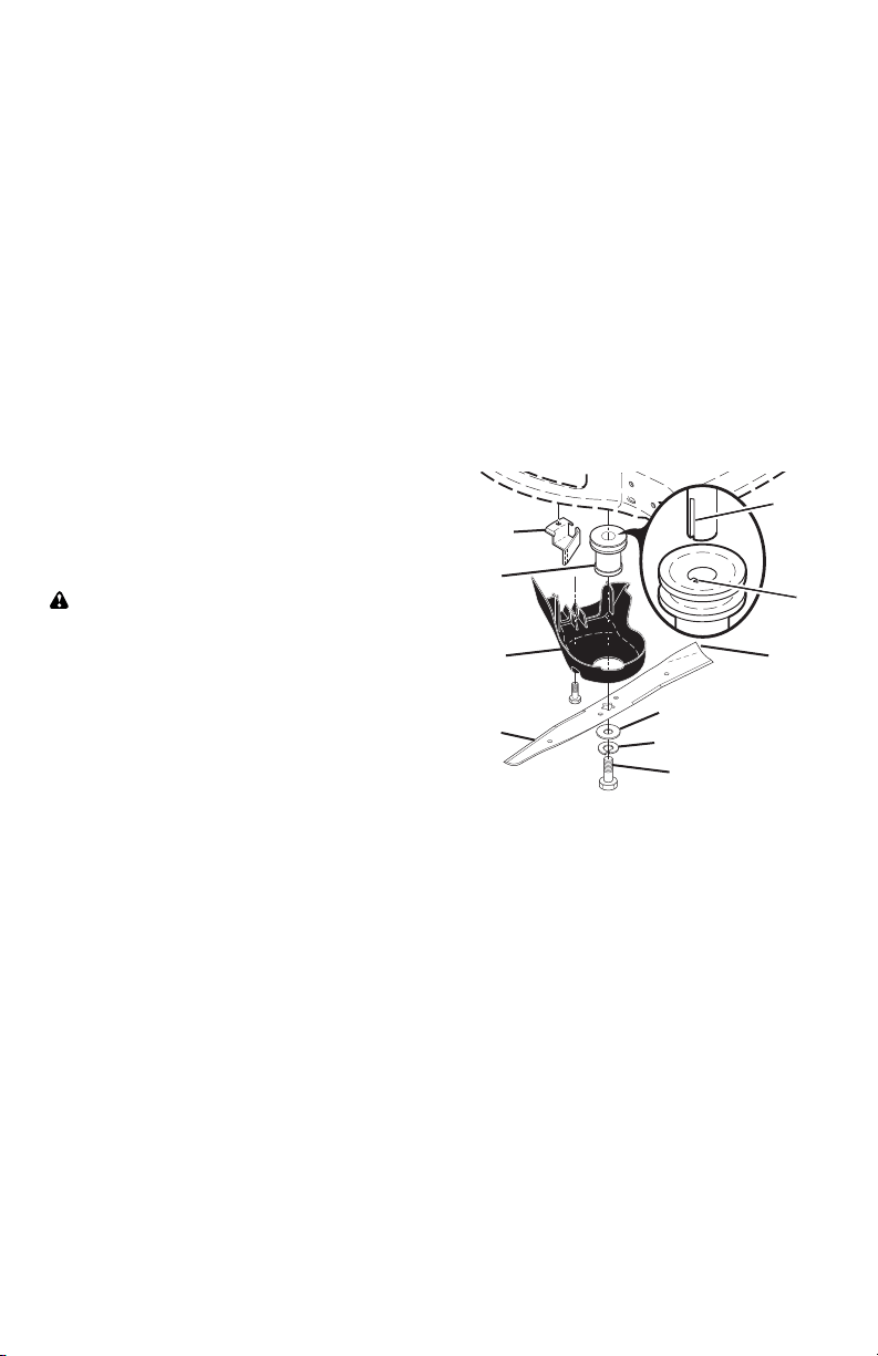
TO REMOVE BLADE
1. Disconnect spark plug wire from spark
plug and place wire where it cannot
come in contact with plug.
2. Turn lawn mower on its side. Make
sure air filter and carburetor are up.
3. Use a wood block between blade and
mower hous ing to prevent blade from
turning when re mov ing blade bolt.
NOTE: Protect your hands with gloves
and/or wrap blade with heavy cloth.
4. Remove blade bolt by turning counter-
clockwise.
5. Remove blade and attaching hardware
(bolt, lock wash er, hardened wash er).
6. Remove debris shield.
NOTE: Remove the blade adapter
and check the key inside hub of blade
adapter. The key must be in good condi-
tion to work properly. Replace adapter if
damaged.
TO REPLACE BLADE
1. Position the blade adapter on the
engine crank shaft. Be sure key in
adapter and crankshaft keyway are
aligned; and that the drive belt is
inside the tab of the belt retainer.
2. Install debris shield.
3. Position blade on the blade adapter.
IMPORTANT: To ensure proper as sem bly,
center hole in blade must align with star
on blade adapter.
4. Be sure the trailing edge of blade (op-
posite sharp edge) is up toward the
engine.
5. Install the blade bolt with the lock
washer and hardened washer into
blade adapter and crankshaft.
6. Use block of wood between blade and
lawn mower housing and tighten the
blade bolt, turning clockwise.
• The recommended tightening torque is
35–40 ft. lbs. (47–54 Nm).
IMPORTANT: Blade bolt is heat treated.
If bolt needs replacing, replace only with
approved bolt shown in the Repair Parts
section of this manual.
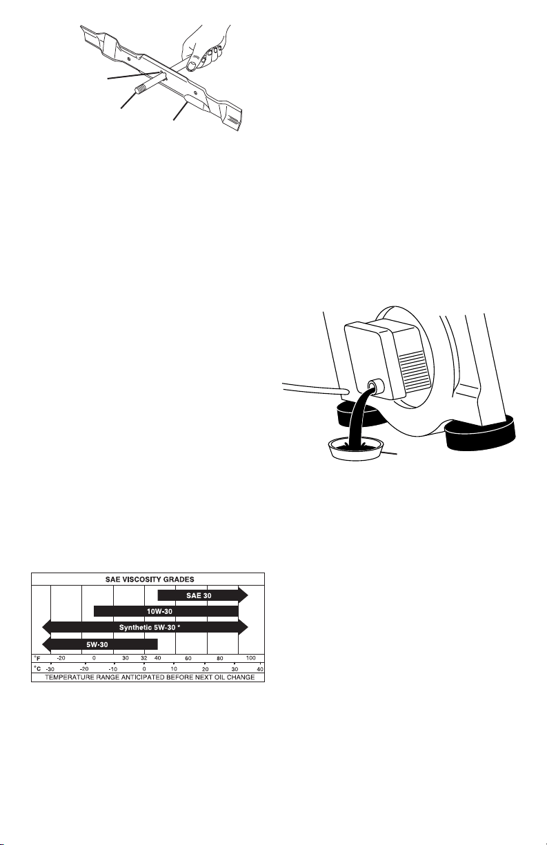
TO SHARPEN BLADE
NOTE: We do not recommend sharp-
en ing blade - but if you do, be sure the
blade is balanced. An un bal anced blade
will cause eventual damage to lawn
mower or engine.
• The blade can be sharp ened with a file
or on a grinding wheel. Do not attempt
to sharpen while on the mower.
• To check blade balance, you will need
a 5/8" diameter steel bolt, pin, or a cone
balancer. (When using a cone bal anc-
er, follow the in struc tions supplied with
bal anc er.)
NOTE: Do not use a nail for balancing
blade. The lobes of the center hole may
appear to be centered, but are not.
• Slide blade on to an unthreaded portion
of the steel bolt or pin and hold the
bolt or pin parallel with the ground. If
blade is bal anced, it should remain in a
horizontal po si tion. If either end of the
blade moves downward, sharpen the
heavy end until the blade is balanced.
Blade bolt
Crank-
shaft
keyway
Hardened washer
Lockwasher
Blade
adapter
Key
Blade
Trailing
edge
Belt
retainer
Debris
shield
19
ENGINE
FUEL SYS TEM
IMPORTANT: It is important to prevent
gum deposits from forming in essential
fuel system parts such as carburetor, fuel
filter, fuel hose, or tank during storage.
Alcohol blended fuels (called gasohol or
using ethanol or methanol) can attract
moisture which leads to separation and
formation of acids during storage. Acidic
gas can damage the fuel system of an
engine while in storage.
• Empty the fuel tank by starting the en-
gine and letting it run until the fuel lines
and car bu re tor are empty.
• Never use engine or carburetor cleaner
prod ucts in the fuel tank or permanent
damage may occur.
• Use fresh fuel next season.
NOTE: Fuel stabilizer is an acceptable
alternative in min i miz ing the formation of
fuel gum deposits during stor age. Add
stabilizer to gasoline in fuel tank or stor-
age container. Always follow the mix ratio
found on stabilizer container. Run engine
at least 10 min utes after adding stabilizer
to allow the stabilizer to reach the car-
buretor. Do not empty the gas tank and
carburetor if using fuel stabilizer.
CYLINDER
1. Remove spark plug.
2. Pour one ounce (29 ml) of oil through
spark plug hole into cylinder.
3. Pull starter handle slowly a few times
to dis trib ute oil.
4. Replace with new spark plug.
OTHER
• Do not store gasoline from one season
to another.
• Replace your gasoline can if your can
starts to rust. Rust and/or dirt in your
gasoline will cause problems.
• If possible, store your unit indoors and
cover it to protect it from dust and dirt.
• Cover your unit with a suitable pro tec-
tive cover that does not retain mois ture.
Do not use plastic. Plastic cannot
breathe, which allows condensation to
form and will cause your unit to rust.
IMPORTANT: Never cover mower while
engine and exhaust areas are still warm.
CAUTION: Never store the lawn mower
with gaso line in the tank in side a build ing
where fumes may reach an open flame
or spark. Allow the engine to cool before
storing in any enclosure.
18
IMPORTANT: Never tamper with the
engine governor, which is factory set
for proper engine speed. Over speed-
ing the engine above the factory high
speed setting can be dangerous. If you
think the engine-governed high speed
needs adjusting, contact a Sears or other
qualified service center, which has proper
equip ment and ex pe ri ence to make any
nec es sary adjustments.
ENGINE
ENGINE SPEED
Your engine speed has been factory set.
CARBURETOR
Your carburetor is not adjustable.
STORAGE
Immediately prepare your lawn mower for storage at the end of the season or if the unit
will not be used for 30 days or more.
LAWN MOWER
When lawn mower is to be stored for a
period of time, clean it thor oughly, remove
all dirt, grease, leaves, etc. Store in a
clean, dry area.
1. Clean entire lawn mower (See
“CLEANING” in the Maintenance sec-
tion of this manual).
2. Lubricate as shown in the Main te-
nance section of this manual.
3. Be sure that all nuts, bolts, screws,
and pins are securely fas tened. In-
spect moving parts for damage, break-
age and wear. Replace if necessary.
4. Touch up all rusted or chipped paint
surfaces; sand lightly before painting.
HANDLE
You can fold your han dle for storage.
1. Loosen the two (2) handle knobs on
sides of the upper handle and allow
handle to fold down to the rear.
2. Remove the two (2) handle knobs and
carriage bolts on sides of the lower
handle and pivot entire handle as sem bly
forward and allow it to rest on mower.
3. Reinstall knobs and carriage bolts to
lower handle / handle brackets for safe
keeping.
• When setting up your handle from
the storage position, lower han dle will
require manually locking into mowing
position.
IMPORTANT: When folding the handle
for storage or transportation, be sure to
fold the handle as shown or you may
damage the control cables.
FOLD
FORWARD
FOR
STORAGE
MOWING
POSITION
Lower handle
Operator
presence
control bar
Upper
handle
Handle
knob
Handle
bracket
Knob
Bolt
15
5/8" bolt or pin
Center hole
Blade
GRASS CATCHER
• The grass catcher may be hosed with
water, but must be dry when used.
• Check your grass catcher often for
damage or de te ri o ra tion. Through
normal use it will wear. If catcher needs
replacing, replace only with ap proved
replacement catcher shown in the Re-
pair Parts section of this manual. Give
the lawn mower model number when
ordering.
GEAR CASE
• To keep your drive system work-
ing properly, the gear case and area
around the drive should be kept clean
and free of trash build-up. Clean under
the drive cover twice a season.
• The gear case is filled with lubricant to the
proper level at the factory. The only time
the lubricant needs attention is if service
has been performed on the gear case.
ENGINE
LUBRICATION
Use only high quality detergent oil rated
with API service classification SJ–SN.
Select the oil's SAE viscosity grade
according to your expected operating
temperature.
* NOTE: An oil change is not required but
if you desire to change the oil follow the
procedure below.
Check the crankcase oil level before
starting the engine and after each five (5)
hours of continuous use. Tighten oil plug
securely each time you check the oil level.
TO CHANGE ENGINE OIL
NOTE: Before tipping lawn mower to
drain oil, empty fuel tank by running en-
gine until fuel tank is empty.
1. Disconnect spark plug wire from spark
plug and place wire where it cannot
come in contact with plug.
2. Remove engine oil cap; lay aside on a
clean surface.
3. Tip lawn mower on its side as shown
and drain oil into a suitable container.
Rock lawn mower back and forth to re-
move any oil trapped inside of engine.
NOTE: Although multi-viscosity oils
(5W30, 10W30 etc.) improve starting in
cold weather, these multi-viscosity oils will
result in increased oil consumption when
used above 32°F. Check your engine oil
level more frequently to avoid possible en-
gine damage from running low on oil.
4. Wipe off any spilled oil from lawn
mower or side of engine.
5. Slowly pour oil down the oil fill spout,
stopping every few ounces to check
the oil level with the dipstick.
6. Stop adding oil when you reach the
FULL mark on the dipstick. Wait a
minute to allow oil to settle.
7. Continue adding small amounts of oil,
rechecking the dipstick until oil level
settles at FULL. DO NOT overfill, or
engine will smoke heavily from the
muffler on startup.
8. Always be sure to retighten oil dipstick
before starting engine.
9. Re con nect spark plug wire to spark
plug.
Container
16
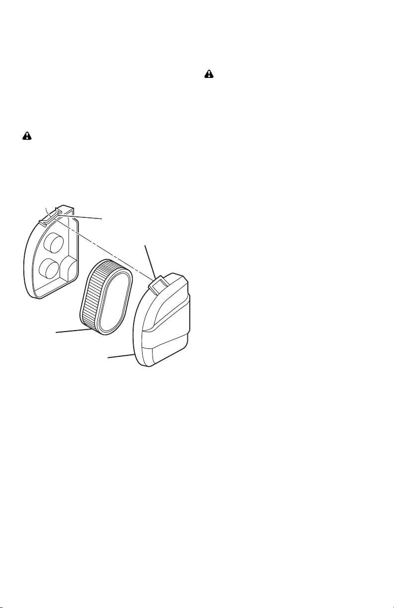
AIR FILTER
Your engine will not run properly and may
be damaged by using a dirty air filter.
Replace the air filter every 100 hours of
operation or every season, whichever oc-
curs first. Service air cleaner more often
under dusty conditions.
TO CLEAN AIR FILTER
1. Remove cover.
2. Carefully remove cartridge.
3. Clean by gently tapping on a flat sur-
face. If very dirty, replace cartridge.
CAUTION: Petroleum solvents, such
as ker o sene, are not to be used to clean
car tridge. They may cause de te ri o ra tion
of the cartridge. Do not oil car tridge. Do
not use pres sur ized air to clean or dry
car tridge.
4. Install cartridge, then replace cover.
CLEANING
IMPORTANT: For best performance,
keep mower housing free of built-grass
and trash. Clean the underside of your
mower after each use.
CAUTION: Disconnect spark plug wire
from spark plug and place wire where it
cannot come in contact with spark plug.
• Clean the underside of your lawn
mower by scraping to remove build-up
of grass and trash.
• Clean engine often to keep trash from
accumulating. A clogged engine runs
hotter and shortens engine life.
• Keep finished surfaces and wheels free
of all gasoline, oil, etc.
• With the exception of the water wash-
out port (if equipped), we do not rec-
ommend using a garden hose to clean
the outside of your lawn mower unless
the elec tri cal system, muffler, air filter
and carburetor are covered to keep
water out. Water in engine can result in
shortened engine life.
CLEAN UNDER DRIVE COVER
Clean under drive cover at least twice a
season. Scrape underside of cover with
putty knife or similar tool to remove any
build-up of trash or grass on underside of
drive cover.
MUFFLER
Inspect and replace corroded muffler as it
could create a fire hazard and/or dam age.
SPARK PLUG
Replace spark plug at the beginning of
each mowing season or after every 100
hours of operation, whichever occurs
first. Spark plug type and gap setting
are shown in the “PROD UCT SPEC I FI CA-
TIONS” section of this manual.
Tab
Cartridge
Filter cover
Slot
17
SERVICE AND ADJUSTMENTS
WARNING: To avoid serious injury,
before performing any service and
adjustments:
1. Release control bar and stop engine.
2. Make sure the blade and all moving
parts have completely stopped.
3. Disconnect spark plug wire from spark
plug and place wire where it cannot
come in contact with plug.
LAWN MOWER
TO ADJUST CUTTING HEIGHT
See “TO ADJUST CUTTING HEIGHT” in
the Operation sec tion of this manual.
REAR DEFLECTOR
The rear deflector, attached between the
rear wheels of your mower, is provided to
min i mize the possibility that objects will be
thrown out of the rear of the mower into the
operator's mowing position. Replace the rear
deflector if it becomes dam aged.
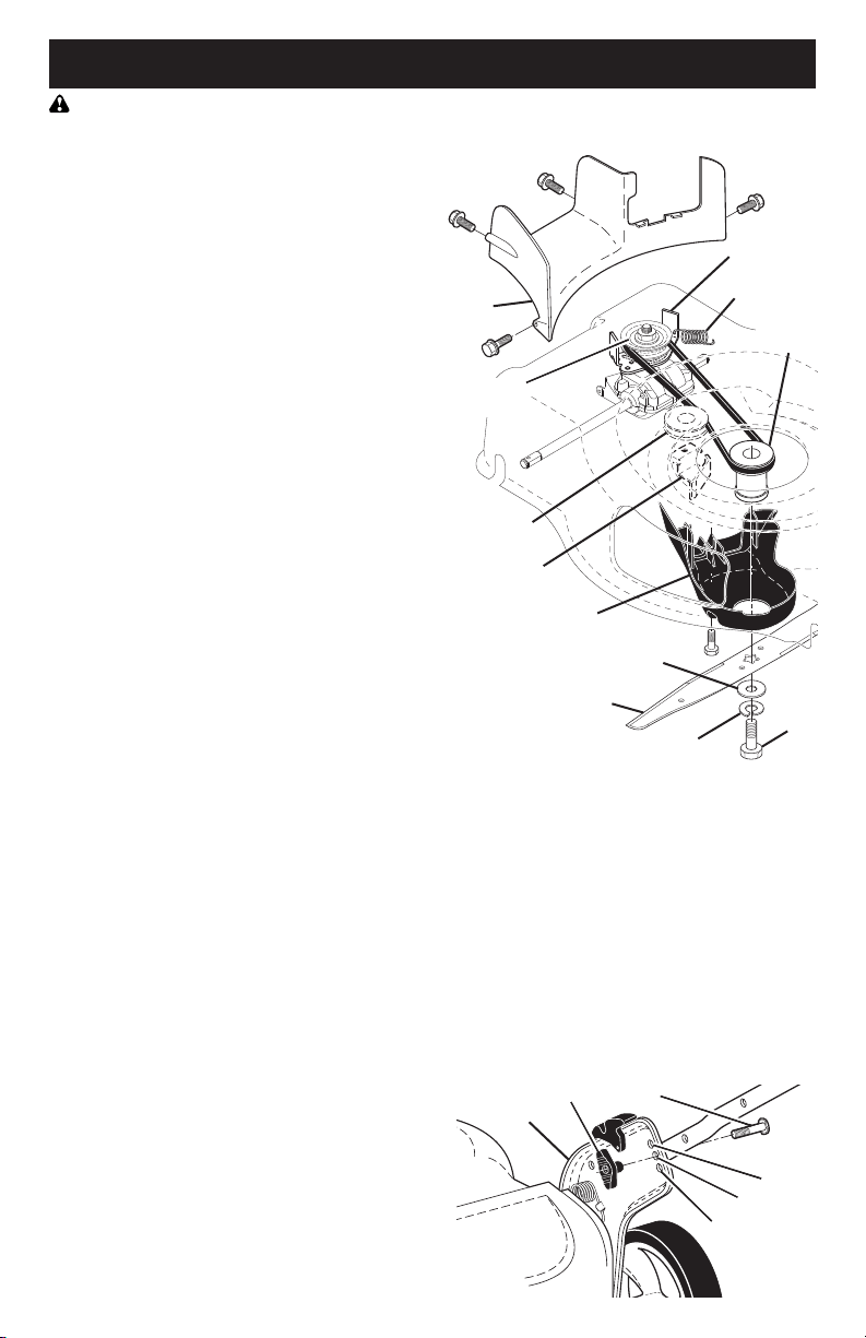
TO REMOVE DRIVE BELT
1. Remove screws securing rear baffle.
2. Turn lawn mower on its side with air
filter and car bu re tor up.
3. Remove rear baffle from mower.
4. Disconnect return spring from rear baffle
/ rear gearcase belt keeper.
5. Remove blade bolt, lockwasher, hard-
ened washer and blade.
6. Remove debris shield.
7. Remove gearcase belt keeper.
8. Remove drive belt.
TO REPLACE DRIVE BELT
1. Place new drive belt on gearcase pulley.
NOTE: Always use factory approved belt
to assure proper fit and long life.
2. Reinstall gearcase belt keeper. Be
sure the new drive belt is inside the
tabs of the gearcase belt keeper.
3. Position the blade adapter on the
engine crank shaft. Be sure key in
adapter and crankshaft keyway are
aligned; and that the new drive belt is
inside the tabs of the belt retainer.
4. Reattach return spring to rear baffle /
rear gearcase belt keeper.
5. Place rear baffle in mower housing.
6. Reinstall debris shield.
7. Reinstall blade. The recommended
tightening torque is 35–40 ft. lbs.
(47–54 Nm).
8. Return mower to upright po si tion.
9. Reinstall rear baffle screws.
Handle
bracket
Low
Knob
High
Medium
Bolt
TO ADJUST HANDLE
Your handle has three (3) height positions
- adjust to a height that suits you.
1. Remove knob and carriage bolt on
one side of the lower handle.
2. While holding handle assembly,
remove knob and car riage bolt from
opposite side, align hole in handle with
desired hole in handle bracket and
reassemble bolt and knob and tighten
securely.
3. Align opposite side of handle with
same positioning hole and secure with
bolt and knob.
Blade
bolt
Hardened washer
Lockwasher
Blade
adapter
Blade
Belt retainer
Gearcase
belt keeper
Return spring
Debris shield
Idler pulley
Rear
baffle
Gearcase
pulley
16
AIR FILTER
Your engine will not run properly and may
be damaged by using a dirty air filter.
Replace the air filter every 100 hours of
operation or every season, whichever oc-
curs first. Service air cleaner more often
under dusty conditions.
TO CLEAN AIR FILTER
1. Remove cover.
2. Carefully remove cartridge.
3. Clean by gently tapping on a flat sur-
face. If very dirty, replace cartridge.
CAUTION: Petroleum solvents, such
as ker o sene, are not to be used to clean
car tridge. They may cause de te ri o ra tion
of the cartridge. Do not oil car tridge. Do
not use pres sur ized air to clean or dry
car tridge.
4. Install cartridge, then replace cover.
CLEANING
IMPORTANT: For best performance,
keep mower housing free of built-grass
and trash. Clean the underside of your
mower after each use.
CAUTION: Disconnect spark plug wire
from spark plug and place wire where it
cannot come in contact with spark plug.
• Clean the underside of your lawn
mower by scraping to remove build-up
of grass and trash.
• Clean engine often to keep trash from
accumulating. A clogged engine runs
hotter and shortens engine life.
• Keep finished surfaces and wheels free
of all gasoline, oil, etc.
• With the exception of the water wash-
out port (if equipped), we do not rec-
ommend using a garden hose to clean
the outside of your lawn mower unless
the elec tri cal system, muffler, air filter
and carburetor are covered to keep
water out. Water in engine can result in
shortened engine life.
CLEAN UNDER DRIVE COVER
Clean under drive cover at least twice a
season. Scrape underside of cover with
putty knife or similar tool to remove any
build-up of trash or grass on underside of
drive cover.
MUFFLER
Inspect and replace corroded muffler as it
could create a fire hazard and/or dam age.
SPARK PLUG
Replace spark plug at the beginning of
each mowing season or after every 100
hours of operation, whichever occurs
first. Spark plug type and gap setting
are shown in the “PROD UCT SPEC I FI CA-
TIONS” section of this manual.
Tab
Cartridge
Filter cover
Slot
17
SERVICE AND ADJUSTMENTS
WARNING: To avoid serious injury,
before performing any service and
adjustments:
1. Release control bar and stop engine.
2. Make sure the blade and all moving
parts have completely stopped.
3. Disconnect spark plug wire from spark
plug and place wire where it cannot
come in contact with plug.
LAWN MOWER
TO ADJUST CUTTING HEIGHT
See “TO ADJUST CUTTING HEIGHT” in
the Operation sec tion of this manual.
REAR DEFLECTOR
The rear deflector, attached between the
rear wheels of your mower, is provided to
min i mize the possibility that objects will be
thrown out of the rear of the mower into the
operator's mowing position. Replace the rear
deflector if it becomes dam aged.
TO REMOVE DRIVE BELT
1. Remove screws securing rear baffle.
2. Turn lawn mower on its side with air
filter and car bu re tor up.
3. Remove rear baffle from mower.
4. Disconnect return spring from rear baffle
/ rear gearcase belt keeper.
5. Remove blade bolt, lockwasher, hard-
ened washer and blade.
6. Remove debris shield.
7. Remove gearcase belt keeper.
8. Remove drive belt.
TO REPLACE DRIVE BELT
1. Place new drive belt on gearcase pulley.
NOTE: Always use factory approved belt
to assure proper fit and long life.
2. Reinstall gearcase belt keeper. Be
sure the new drive belt is inside the
tabs of the gearcase belt keeper.
3. Position the blade adapter on the
engine crank shaft. Be sure key in
adapter and crankshaft keyway are
aligned; and that the new drive belt is
inside the tabs of the belt retainer.
4. Reattach return spring to rear baffle /
rear gearcase belt keeper.
5. Place rear baffle in mower housing.
6. Reinstall debris shield.
7. Reinstall blade. The recommended
tightening torque is 35–40 ft. lbs.
(47–54 Nm).
8. Return mower to upright po si tion.
9. Reinstall rear baffle screws.
Handle
bracket
Low
Knob
High
Medium
Bolt
TO ADJUST HANDLE
Your handle has three (3) height positions
- adjust to a height that suits you.
1. Remove knob and carriage bolt on
one side of the lower handle.
2. While holding handle assembly,
remove knob and car riage bolt from
opposite side, align hole in handle with
desired hole in handle bracket and
reassemble bolt and knob and tighten
securely.
3. Align opposite side of handle with
same positioning hole and secure with
bolt and knob.
Blade
bolt
Hardened washer
Lockwasher
Blade
adapter
Blade
Belt retainer
Gearcase
belt keeper
Return spring
Debris shield
Idler pulley
Rear
baffle
Gearcase
pulley
18
IMPORTANT: Never tamper with the
engine governor, which is factory set
for proper engine speed. Over speed-
ing the engine above the factory high
speed setting can be dangerous. If you
think the engine-governed high speed
needs adjusting, contact a Sears or other
qualified service center, which has proper
equip ment and ex pe ri ence to make any
nec es sary adjustments.
ENGINE
ENGINE SPEED
Your engine speed has been factory set.
CARBURETOR
Your carburetor is not adjustable.
STORAGE
Immediately prepare your lawn mower for storage at the end of the season or if the unit
will not be used for 30 days or more.
LAWN MOWER
When lawn mower is to be stored for a
period of time, clean it thor oughly, remove
all dirt, grease, leaves, etc. Store in a
clean, dry area.
1. Clean entire lawn mower (See
“CLEANING” in the Maintenance sec-
tion of this manual).
2. Lubricate as shown in the Main te-
nance section of this manual.
3. Be sure that all nuts, bolts, screws,
and pins are securely fas tened. In-
spect moving parts for damage, break-
age and wear. Replace if necessary.
4. Touch up all rusted or chipped paint
surfaces; sand lightly before painting.
HANDLE
You can fold your han dle for storage.
1. Loosen the two (2) handle knobs on
sides of the upper handle and allow
handle to fold down to the rear.
2. Remove the two (2) handle knobs and
carriage bolts on sides of the lower
handle and pivot entire handle as sem bly
forward and allow it to rest on mower.
3. Reinstall knobs and carriage bolts to
lower handle / handle brackets for safe
keeping.
• When setting up your handle from
the storage position, lower han dle will
require manually locking into mowing
position.
IMPORTANT: When folding the handle
for storage or transportation, be sure to
fold the handle as shown or you may
damage the control cables.
FOLD
FORWARD
FOR
STORAGE
MOWING
POSITION
Lower handle
Operator
presence
control bar
Upper
handle
Handle
knob
Handle
bracket
Knob
Bolt
15
5/8" bolt or pin
Center hole
Blade
GRASS CATCHER
• The grass catcher may be hosed with
water, but must be dry when used.
• Check your grass catcher often for
damage or de te ri o ra tion. Through
normal use it will wear. If catcher needs
replacing, replace only with ap proved
replacement catcher shown in the Re-
pair Parts section of this manual. Give
the lawn mower model number when
ordering.
GEAR CASE
• To keep your drive system work-
ing properly, the gear case and area
around the drive should be kept clean
and free of trash build-up. Clean under
the drive cover twice a season.
• The gear case is filled with lubricant to the
proper level at the factory. The only time
the lubricant needs attention is if service
has been performed on the gear case.
ENGINE
LUBRICATION
Use only high quality detergent oil rated
with API service classification SJ–SN.
Select the oil's SAE viscosity grade
according to your expected operating
temperature.
* NOTE: An oil change is not required but
if you desire to change the oil follow the
procedure below.
Check the crankcase oil level before
starting the engine and after each five (5)
hours of continuous use. Tighten oil plug
securely each time you check the oil level.
TO CHANGE ENGINE OIL
NOTE: Before tipping lawn mower to
drain oil, empty fuel tank by running en-
gine until fuel tank is empty.
1. Disconnect spark plug wire from spark
plug and place wire where it cannot
come in contact with plug.
2. Remove engine oil cap; lay aside on a
clean surface.
3. Tip lawn mower on its side as shown
and drain oil into a suitable container.
Rock lawn mower back and forth to re-
move any oil trapped inside of engine.
NOTE: Although multi-viscosity oils
(5W30, 10W30 etc.) improve starting in
cold weather, these multi-viscosity oils will
result in increased oil consumption when
used above 32°F. Check your engine oil
level more frequently to avoid possible en-
gine damage from running low on oil.
4. Wipe off any spilled oil from lawn
mower or side of engine.
5. Slowly pour oil down the oil fill spout,
stopping every few ounces to check
the oil level with the dipstick.
6. Stop adding oil when you reach the
FULL mark on the dipstick. Wait a
minute to allow oil to settle.
7. Continue adding small amounts of oil,
rechecking the dipstick until oil level
settles at FULL. DO NOT overfill, or
engine will smoke heavily from the
muffler on startup.
8. Always be sure to retighten oil dipstick
before starting engine.
9. Re con nect spark plug wire to spark
plug.
Container

14
LAWN MOWER
Always observe safety rules when per-
form ing any main te nance.
TIRES
• Keep tires free of gasoline, oil, or insect
control chemi cals which can harm rubber.
• Avoid stumps, stones, deep ruts, sharp
objects and other hazards that may
cause tire damage.
DRIVE WHEELS
Check rear drive wheels each time you
mow to be sure they move freely. The
wheels not turning freely means trash,
grass cuttings, etc., may be inside the
drive wheel and dust cover area and must
be cleaned out to free drive wheels.
If necessary to clean the drive wheels,
check both rear wheels.
BLADE CARE
For best results, mower blade must be
kept sharp. Re place a bent or dam aged
blade.
CAUTION: Use only a replacement
blade approved by the manufacturer of
your mower. Using a blade not approved
by the manufacturer of your mower is
hazardous, could damage your mower
and void your warranty.
TO REMOVE BLADE
1. Disconnect spark plug wire from spark
plug and place wire where it cannot
come in contact with plug.
2. Turn lawn mower on its side. Make
sure air filter and carburetor are up.
3. Use a wood block between blade and
mower hous ing to prevent blade from
turning when re mov ing blade bolt.
NOTE: Protect your hands with gloves
and/or wrap blade with heavy cloth.
4. Remove blade bolt by turning counter-
clockwise.
5. Remove blade and attaching hardware
(bolt, lock wash er, hardened wash er).
6. Remove debris shield.
NOTE: Remove the blade adapter
and check the key inside hub of blade
adapter. The key must be in good condi-
tion to work properly. Replace adapter if
damaged.
TO REPLACE BLADE
1. Position the blade adapter on the
engine crank shaft. Be sure key in
adapter and crankshaft keyway are
aligned; and that the drive belt is
inside the tab of the belt retainer.
2. Install debris shield.
3. Position blade on the blade adapter.
IMPORTANT: To ensure proper as sem bly,
center hole in blade must align with star
on blade adapter.
4. Be sure the trailing edge of blade (op-
posite sharp edge) is up toward the
engine.
5. Install the blade bolt with the lock
washer and hardened washer into
blade adapter and crankshaft.
6. Use block of wood between blade and
lawn mower housing and tighten the
blade bolt, turning clockwise.
• The recommended tightening torque is
35–40 ft. lbs. (47–54 Nm).
IMPORTANT: Blade bolt is heat treated.
If bolt needs replacing, replace only with
approved bolt shown in the Repair Parts
section of this manual.
TO SHARPEN BLADE
NOTE: We do not recommend sharp-
en ing blade - but if you do, be sure the
blade is balanced. An un bal anced blade
will cause eventual damage to lawn
mower or engine.
• The blade can be sharp ened with a file
or on a grinding wheel. Do not attempt
to sharpen while on the mower.
• To check blade balance, you will need
a 5/8" diameter steel bolt, pin, or a cone
balancer. (When using a cone bal anc-
er, follow the in struc tions supplied with
bal anc er.)
NOTE: Do not use a nail for balancing
blade. The lobes of the center hole may
appear to be centered, but are not.
• Slide blade on to an unthreaded portion
of the steel bolt or pin and hold the
bolt or pin parallel with the ground. If
blade is bal anced, it should remain in a
horizontal po si tion. If either end of the
blade moves downward, sharpen the
heavy end until the blade is balanced.
Blade bolt
Crank-
shaft
keyway
Hardened washer
Lockwasher
Blade
adapter
Key
Blade
Trailing
edge
Belt
retainer
Debris
shield
19
ENGINE
FUEL SYS TEM
IMPORTANT: It is important to prevent
gum deposits from forming in essential
fuel system parts such as carburetor, fuel
filter, fuel hose, or tank during storage.
Alcohol blended fuels (called gasohol or
using ethanol or methanol) can attract
moisture which leads to separation and
formation of acids during storage. Acidic
gas can damage the fuel system of an
engine while in storage.
• Empty the fuel tank by starting the en-
gine and letting it run until the fuel lines
and car bu re tor are empty.
• Never use engine or carburetor cleaner
prod ucts in the fuel tank or permanent
damage may occur.
• Use fresh fuel next season.
NOTE: Fuel stabilizer is an acceptable
alternative in min i miz ing the formation of
fuel gum deposits during stor age. Add
stabilizer to gasoline in fuel tank or stor-
age container. Always follow the mix ratio
found on stabilizer container. Run engine
at least 10 min utes after adding stabilizer
to allow the stabilizer to reach the car-
buretor. Do not empty the gas tank and
carburetor if using fuel stabilizer.
CYLINDER
1. Remove spark plug.
2. Pour one ounce (29 ml) of oil through
spark plug hole into cylinder.
3. Pull starter handle slowly a few times
to dis trib ute oil.
4. Replace with new spark plug.
OTHER
• Do not store gasoline from one season
to another.
• Replace your gasoline can if your can
starts to rust. Rust and/or dirt in your
gasoline will cause problems.
• If possible, store your unit indoors and
cover it to protect it from dust and dirt.
• Cover your unit with a suitable pro tec-
tive cover that does not retain mois ture.
Do not use plastic. Plastic cannot
breathe, which allows condensation to
form and will cause your unit to rust.
IMPORTANT: Never cover mower while
engine and exhaust areas are still warm.
CAUTION: Never store the lawn mower
with gaso line in the tank in side a build ing
where fumes may reach an open flame
or spark. Allow the engine to cool before
storing in any enclosure.

20
Does not start 1. Dirty air filter. 1. Clean/replace air filter.
2. Out of fuel. 2. Fill fuel tank.
3. Stale fuel. 3. Empty fuel tank and refill tank
with fresh, clean gasoline.
4. Water in fuel. 4. Empty fuel tank and refill tank
with fresh, clean gasoline.
5. Spark plug wire is 5. Connect wire to plug.
disconnected.
6. Bad spark plug. 6. Replace spark plug.
7. Loose blade or broken 7. Tighten blade bolt or
blade adapter. replace blade adapter.
8. Control bar in released 8. Depress control bar to
position. handle.
9. Control bar defective. 9. Replace control bar.
10. Fuel valve lever (if so 10. Turn fuel valve lever
equipped) in OFF position. to the ON position.
11. Weak battery (if equipped). 11. Charge battery.
12. Disconnected battery 12. Connect battery to engine.
connector (if equipped).
13. Blown fuse (if equipped). 13. Replace fuse.
PROBLEM CAUSE CORRECTION
TROUBLESHOOTING - See appropriate section in manual unless directed
to a Sears Parts & Repair Centre.
13
MAINTENANCE
GENERAL REC OM MEN DA TIONS
The warranty on this lawn mower does not
cover items that have been sub ject ed to
operator abuse or negligence. To receive
full value from the warranty, operator must
maintain unit as in struct ed in this manual.
Some adjustments will need to be made
periodically to properly maintain your unit.
At least once a season, check to see if
you should make any of the adjustments
described in the Service and Ad just ments
section of this manual.
• At least once a year, replace the spark
plug, clean or replace air filter element
and check blade for wear. A new spark
plug and clean/new air filter element
assure proper air-fuel mix ture and help
your engine run bet ter and last longer.
• Follow the maintenance schedule in this
manual.
BEFORE EACH USE
• Check engine oil level.
• Check for loose fasteners.
LUBRICATION
Keep unit well lubricated
(See “LU BRI CA TION CHART”).
LUBRICATION CHART
Spray lubricant
See "ENGINE" in Maintenance section.
Wheel
adjuster (on
each wheel)
Engine oil
Rear
door hinge
Handle bracket mounting pins
Mulcher
door hinge
pin
IMPORTANT: Do not oil or grease plastic
wheel bearings. Viscous lu bri cants will
attract dust and dirt that will short en the life
of the self-lu bri cat ing bearings. If you feel
they must be lu bri cated, use only a dry,
pow dered graphite type lubricant spar ingly.
Check for Loose Fasteners
Clean / Inspect Grass Catcher *
Check Tires
Check Drive Wheels ***
Clean Lawn Mower ****
Clean under Drive Cover ***
Check Drive Belt / Pulleys ***
Check / Sharpen / Replace Blade
Lubrication
Clean and Recharge Battery **
Check Engine Oil level
Clean Air Filter
Inspect Muffler
Replace Spark Plug
Replace Air Filter Paper Cartridge
Empty fuel system or add Stabilizer
BEFORE
EACH
USE
AFTER
EACH
USE
EVERY
10
HOURS
EVERY
25 HOURS
OR SEASON
EVERY
100
HOURS
BEFORE
STORAGE
(if so equipped)
Electric-Start mowers
Power-Propelled mowers
Use a scraper to clean under deck
*
**
***
****
1 - And after each 5 hours of use.
2 - Service more often if operating in dirty or dusty conditions.
3 - Replace blades more often when mowing in sandy soil.
4 - Charge 48 hours at end of season.

12
MULCHING MOWING TIPS
IMPORTANT: For best performance,
keep mower housing free of built-up
grass and trash. See “CLEANING” in the
Maintenance section of this manual.
• The special mulching blade will recut
the grass clip pings many times and
reduce them in size so that as they fall
onto the lawn they will disperse into
the grass and not be noticed. Also,
the mulched grass will bio de grade
quick ly to provide nu tri ents for the lawn.
Always mulch with your highest engine
(blade) speed as this will provide the
best recutting action of the blades.
• Avoid cutting your lawn when it is wet.
Wet grass tends to form clumps and
in ter feres with the mulch ing action. The
best time to mow your lawn is the early
afternoon. At this time the grass has
dried, yet the newly cut area will not be
exposed to direct sunlight.
• For best results, adjust the lawn mower
cutting height so that the lawn mower
cuts off only the top one-third of the
grass blades. If the lawn is over grown
it will be nec es sary to raise the height
of cut to reduce pushing effort and to
keep from over load ing the engine and
leaving clumps of mulched grass. For
ex tremely heavy grass, reduce your
width of cut by overlapping previously
cut path and mow slowly.
• Certain types of grass and grass
con di tions may re quire that an area be
mulched a second time to com pletely
hide the clip pings. When doing a sec-
ond cut, mow across (perpendicular) to
the first cut path.
• Change your cutting pattern from week
to week. Mow north to south one week
then change to east to west the next
week. This will help prevent matting
and graining of the lawn.
MAX 1/3
MOWING TIPS
CAUTION: Do not use de-thatcher
blade attachments on your mower. Such
attachments are hazardous, will damage
your mower and could void your warranty.
• Under certain conditions, such as very
tall grass, it may be necessary to raise
the height of cut to reduce pushing
effort and to keep from over load ing the
en gine and leaving clumps of grass
clippings. It may also be necessary to
reduce ground speed and/or run the
lawn mower over the area a second
time.
• For extremely heavy cutting, reduce the
width of cut by overlapping pre vi ous ly
cut path and mow slowly.
• For side discharge operation, cut in
a coun ter clock wise di rec tion, start ing
at the outside of the area to be cut, in
order to spread grass clip pings more
evenly and to put less load on the
engine. To keep clip pings off of walk-
ways, flower beds, etc., make the first
cuts in a clock wise direction.
• If a trail of grass clipping is left on the
right side of the lawn mower during rear
discharge operation, mow in a clock-
wise direction with a small overlap to
collect the clippings on the next pass.
• Pores in cloth grass catchers can be-
come filled with dirt and dust with use
and catchers will collect less grass. To
prevent this, regularly hose catcher off
with water and let dry before using.
• Keep top of engine around starter clear
and clean of grass clippings and chaff.
This will help engine air flow and extend
engine life.
21
Loss of power 1. Rear of lawn mower 1. Raise cutting height.
housing or cutting blade
dragging in heavy grass.
2. Cutting too much grass. 2. Raise cutting height.
3. Dirty air filter. 3. Clean/replace air filter.
4. Buildup of grass, leaves, 4. Clean underside of mower
and trash under mower. housing.
5. Too much oil in engine. 5. Check oil level.
6. Walking speed too fast. 6. Cut at slower walking speed.
Poor cut – 1. Worn, bent or loose blade. 1. Replace blade. Tighten
uneven blade bolt.
2. Wheel heights uneven. 2. Set all wheels at same
height.
3. Buildup of grass, leaves 3. Clean underside of
and trash under mower. mower housing.
Excessive 1. Worn, bent or loose blade. 1. Replace blade. Tighten
vibration blade bolt.
2. Bent engine crankshaft. 2. Contact a Sears or other
qualified service centre.
Starter rope 1. Engine flywheel brake is on 1. Depress control bar to
hard to pull when control bar is released. upper handle before
pulling starter rope.
2. Bent engine crankshaft. 2. Contact a Sears or other
qualified service centre.
3. Blade adapter broken. 3. Replace blade adapter.
4. Blade dragging in grass. 4. Move lawn mower to cut
grass or to hard surface.
Grass catcher 1. Cutting height too low. 1. Raise cutting height.
not filling 2. Lift on blade worn off. 2. Replace blade.
(If so equipped) 3. Catcher not venting air. 3. Clean grass catcher.
Hard to push 1. Grass is too high or wheel 1. Raise cutting height.
height is too low.
2. Rear of lawn mower 2. Raise rear of lawn mower
housing or cutting blade housing one (1) setting
dragging in grass. higher.
3. Grass catcher too full. 3. Empty grass catcher.
4. Handle height position not 4. Adjust handle height to suit.
right for you.
Loss of drive 1. Belt wear. 1. Check/replace drive belt.
or slowing of 2. Belt off of pulley. 2. Check/reinstall drive belt.
drive speed 3. Drive cable worn or broken. 3. Replace drive cable.
4. “Loose” drive control system. 4. Adjust drive control.
PROBLEM CAUSE CORRECTION
TROUBLESHOOTING - See appropriate section in manual unless directed
to a Sears Parts & Repair Centre.
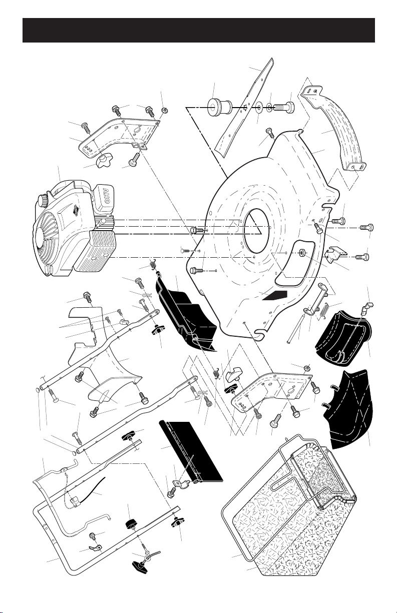
22
CRAFTSMAN ROTARY LAWN MOWER - - MODEL NUMBER 944.364702
REPAIR PARTS
1
3
7
8
9
21
30
31
32
33
36
53
38
39
42
44
45
46
47
48
49
50
51
52
53
57
22
34
53
57
28
28
22
34
40
41
41
43
53
97
59
13
11
17
26
56
56
58
59
11
26
59
24
20
83
85
2
6
6
6
6
84
96
18
19
64
56
84
11
TO STOP ENGINE
• To stop engine, release operator pres-
ence con trol bar.
TO START ENGINE
NOTE: Due to protective coatings on the
engine, a small amount of smoke may be
present during the initial use of the prod-
uct and should be considered normal.
NOTE: Your engine is equipped with an
automatic choke system. No priming or
choking is required before starting.
• To start engine, hold operator presence
control bar down to the han dle and
pull starter handle quickly. Do not allow
starter rope to snap back.
BEFORE STARTING ENGINE
ADD OIL
Your lawnmower is shipped without oil in
the engine. For type and grade of oil to
use, see “EN GINE” in the Maintenance
section of this manual.
CAUTION: DO NOT overfill engine with
oil, or it will smoke heavily from the muffler
on startup.
1. Be sure lawnmower is level.
2. Remove oil dipstick from oil fill spout.
3. You receive a container of oil with the
unit. Slowly pour the entire container
down the oil fill spout into the engine.
NOTE: Initial oil fill requires only 18 oz.
due to residual oil in engine from the
manufacturers 100% quality testing. When
changing oil you may need 20 oz.
4. Insert and tighten dipstick.
IMPORTANT:
• Check oil level before each use. Add
oil if needed. Fill to full line on dipstick.
ADD GASOLINE
• Fill fuel tank to bottom of tank filler
neck. Do not overfill. Use fresh, clean,
regular unleaded gasoline with a mini-
mum of 87 octane. Do not mix oil with
gasoline. Purchase fuel in quan ti ties
that can be used within 30 days to as-
sure fuel freshness.
CAUTION: Wipe off any spilled oil or
fuel. Do not store, spill or use gasoline
near an open flame.
CAUTION: Alcohol blended fuels
(called gasohol or using ethanol or meth-
anol) can attract moisture which leads to
separation and for ma tion of acids during
storage. Acidic gas can damage the fuel
system of an engine while in storage. To
avoid engine problems, the fuel system
should be emptied before stor age of 30
days or longer. Empty the gas tank, start
the engine and let it run until the fuel lines
and carburetor are empty. Use fresh fuel
next season. See Storage In struc tions for
additional information. Never use engine
or carburetor cleaner products in the fuel
tank or permanent damage may occur.
Engine oil cap Gasoline filler
cap

10
SIMPLE STEPS TO
REMEMBER WHEN
CONVERTING YOUR LAWN MOWER
FOR MULCHING -
1. Rear door closed.
2. Mulcher door closed and locked.
FOR REAR BAGGING -
1. Grass catcher installed.
2. Mulcher door closed and locked.
FOR SIDE DISCHARGING -
1. Rear door closed.
2. Discharge deflector installed.
CAUTION: Do not run your lawn mow-
er with out rear door closed or ap proved
grass catcher in place. Never at tempt to
op er ate the lawn mow er with the rear door
re moved or propped open.
TO EMPTY GRASS CATCHER
1. Lift up on grass catcher using the
frame han dle.
2. Remove grass catcher with clippings
from under lawn mower han dle.
3. Empty clippings from bag using both
frame handle and bag handle.
NOTE: Do not drag the bag when empty-
ing; it will cause unnecessary wear.
Unlock
latch
Discharge
deflector
Open
mulcher door
SIDE DISCHARGING
• Rear door must be closed.
• Open mulcher door and install dis-
charge deflector under door as shown.
• Mower is now ready for discharging
operation.
• To convert to mulching or bagging
operation, dis charge deflector must be
removed and mulcher door must be
closed and locked.
MOWER IS NOW READY
FOR DISCHARGING
OPERATION
Grass
catcher
frame
handle
Bag
handle
23
CRAFTSMAN ROTARY LAWN MOWER - - MODEL NUMBER 944.364702
NOTE: All component dimensions given in U.S. inches. 1 inch = 25.4 mm.
IMPORTANT: Use only Original Equipment Manufacturer (O.E.M.) replacement parts. Failure to do so could be hazardous, damage your lawn mower and void your warranty.
30 580947303 Grassbag
31 585054703 Frame, Grass Catcher
32 419944X007 Latch, Mulcher Door
33 432642 Mulcher Door
34 419946X615 Bracket, Grassbag
36 175735 Hinge Bracket Assembly
38 419942X428 Discharge Deflector
39 585900702 Handle Bracket, LH
40 585900802 Handle Bracket, RH
41 150406 Screw, Dogpoint
3/8-16 x 1-1/8
42 193000 Spring, Torsion
43 191730 Nut, Hex, Nylock
44 586601602 Kit, Lawn Mower Housing
45 175650 Rod, Hinge
46 585481201 Blade Adapter / Pulley
47 421825 Blade, 22"
48 851074 Washer, Hardened
49 850263 Washer, Helical
50 851084 Screw, Machine, Hex Head
3/8-24 x 1-3/8 Grade 8
KEY PART
NO. NO. DESCRIPTION
1 585864805 Upper Handle Assembly
2 440385 Cable, Engine Zone Control
3 429930X004 Bracket, Upstop
6 189713X428 Handle Knob
7 178848 Screw, Hex Washer Head
#10-16 x 5/8
8 427612X428 Control Bar
9 585847601 Rear Door Assembly
11 425575 Hairpin, Door/Handle Pivot
13 437516 Plug, Handle Bar
17 581782101 Rear Baffle
18 581912601 T-Knob
19 581902101 Rope Guide
20 444501 Rear Skirt
21 419949 Spring, Rear Door, LH, Black
22 141841 Screw, Panhead, Torx #20
24 419948 Spring, Rear Door, RH, Grey
26 419945 Screw, Rear Door /
Handle Pivot
28 586212501 Bolt, Carriage 5/16-18 x 5/8
KEY PART
NO. NO. DESCRIPTION
51 430599 Front Baffle
52 182166 Decal, Danger
53 17000510 Screw
56 17411312 Screw, Hex Washer Head
#13 x 3/4
57 155377 Nut, Hex
58 585908202 Lower Handle
59 191574 Handle Bolt
64 - - - Engine, Briggs & Stratton,
Model Number 93J02-
0098-F1 (See Breakdown)
83 750097 Screw, Hex Washer Head
84 428124 Fastener, Push
85 429801X004 Mounting Bracket, Skirt
96 197991 Clip, Cable
97 581115302 Bracket
- - 423849 Bag of Parts (Includes
Key Numbers 12 and 59)
- - 587785602 Owner’s Manual, English
- - 587785603 Owner's Manual, French
KEY PART
NO. NO. DESCRIPTION
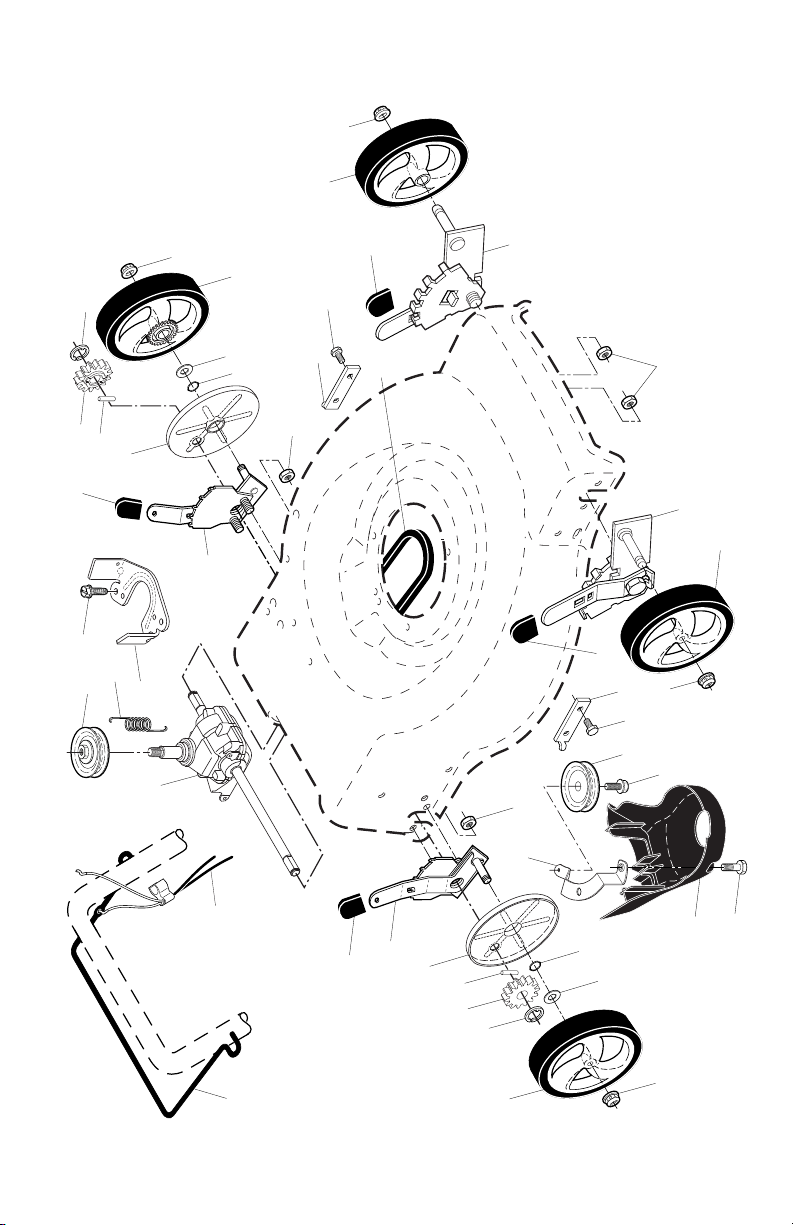
24
CRAFTSMAN ROTARY LAWN MOWER - - MODEL NUMBER 944.364702
33
40
12
13
14
15
16
18
26
27
4
27
4
28
28
29
29
30
30
30
31
31
34
34
35
36
37
55
18
18
18
22
22
59
59
20
25
22
86
87
32
32
33
33
33
40
1
7
9
HOW TO USE YOUR LAWN MOWER
ENGINE SPEED
Engine speed was set at the factory for
optimum performance. It is not adjustable.
ENGINE ZONE CONTROL
CAUTION: Federal regulations re quire
an engine control to be installed on this
lawn mower in order to minimize the risk
of blade contact injury. Do not un der
any circumstances attempt to de feat the
func tion of the operator con trol. The blade
turns when the engine is running.
• Your lawn mower is equipped with an
operator pres ence control bar which
requires the operator to be positioned
behind the lawn mower handle to start
and operate the lawn mower.
TO OPERATE DRIVE SYSTEM
• To start forward motion, lift drive con-
trol bar up to handle.
• To stop forward motion, release drive
control bar.
IMPORTANT: Always keep drive control
fully engaged against handle when in use.
TO ADJUST CUTTING HEIGHT
Raise wheels for low cut and lower wheels
for high cut, adjust cutting height to suit
your requirements. Me di um position is
best for most lawns.
• To change cutting height, squeeze ad-
juster lever to ward wheel. Move wheel
up or down to suit your re quire ments.
Be sure all wheels are in the same set-
ting.
NOTE: Adjuster is properly positioned
when plate tab inserts into hole in lever.
Also, 9-position adjusters (if so equipped)
allow lever to be positioned between the
plate tabs.
TO CONVERT MOWER
Your lawn mower was shipped ready to
be used as a mulcher. To convert to bag-
ging or discharging:
REAR BAGGING
• Lift rear door of the lawn mower and
place the grass catcher frame hooks
onto the grass bag brackets.
• To convert to mulching or dis charg ing
operation, remove grass catch er and
close rear door.
Grass bag
bracket
Grass
catcher
handle
Grass catcher
frame hook
Rear door
DRIVE CONTROL ENGAGED
Operator
pres ence
con trol bar
DRIVE CONTROL DIS EN GAGED
Drive
con trol
bar
ROTATE LEVER TOWARD
ENGINE TO LOWER MOWER
ROTATE LEVER AWAY FROM ENGINE
TO RAISE MOWER
Plate tab Lever
The operation of any lawn mower can result in foreign objects
thrown into the eyes, which can result in severe eye damage.
Always wear safety glasses or eye shields while operating your
lawn mower or performing any adjustments or repairs. We recom-
mend standard safety glasses or a wide vision safety mask over spectacles.
Use ear
protec-
tors to
avoid
damage to hearing.

8
KNOW YOUR LAWN MOWER
READ THIS OWNER'S MANUAL AND ALL SAFETY RULES BEFORE OP ER AT ING YOUR
LAWN MOWER. Compare the illustrations with your lawn mower to familiarize yourself
with the location of various controls and adjustments. Save this manual for future refer-
ence.
These symbols may appear on your lawn mower or in literature supplied with the
product. Learn and understand their meaning.
OPERATION
Wheel adjuster
(on each wheel)
Operator presence control bar
Handle knobs
MEETS CPSC SAFETY REQUIREMENTS
Sears rotary walk-behind power lawn mowers conform to the safety standards of the
American National Standards Institute and the U.S. Consumer Product Safety Com mis-
sion.
WARNING: The blade turns when the engine is running.
Operator presence control bar – must
be held down to the handle to start the
engine. Release to stop the engine.
Primer– pumps additional fuel from the
carburetor to the cylinder for use when
starting a cold engine.
Starter handle – used for starting engine.
Drive control bar – used to engage pow-
er-pro pelled forward mo tion of mower.
Mulcher door – allows con ver sion to
discharging or bagging operation.
Grass
catcher
Drive control bar
Engine oil cap
with dipstick
Air filter
Gasoline filler cap
Housing
Mulcher door
Starter
handle
Spark
plug
IMPORTANT: This lawn mower is shipped
WITHOUT OIL OR GASOLINE in the engine.
NOTE: Gasoline containing up to 10% ethanol (E10) is acceptable for use in this machine.
The use of any gasoline exceeding 10% ethanol (E10) will void the product warranty.
Muffler
25
CRAFTSMAN ROTARY LAWN MOWER - - MODEL NUMBER 944.364702
NOTE: All component dimensions given in U.S. inches. 1 inch = 25.4 mm.
IMPORTANT: Use only Original Equipment Manufacturer (O.E.M.) replacement parts. Failure to do so could be hazardous, damage your lawn mower and void your warranty.
KEY PART
NO. NO. DESCRIPTION
KEY PART
NO. NO. DESCRIPTION
1 586033302 Drive Control Assembly
(Includes Cable)
4 197480 O-Ring
7 194185X428 Control Bar, Drive
12 580364604 Belt, Drive
13 581680801 Gear Case Assembly, Complete
14 586963001 Pulley, Drive
15 581497908 Wheel Adjuster, Rear, RH
16 581497907 Wheel Adjuster, Rear, LH
18 701037 Selector Knob
20 580806901 Debris Shield
22 17000510 Screw, Hex Head 5/16-18
25 581313802 Mounting Bracket, Debris Shield
26 589318301 Bracket, Gearcase
27 67725 Washer
28 12000058 E-Ring 7/16
29 581840401 Cover, Dust, Wheel
30 191730 Nut, Hex
31 404845 Pawl, Drive
32 581685301 Wheel & Tire Assembly, Rear
33 409148 Nut, Flangelock 3/8-16
34 404835 Pinion
35 431138 Wheel Adjuster, Front, RH
36 431139 Wheel Adjuster, Front, LH
37 163409 Screw, Hi-Lo Thread
40 400246X460 Wheel & Tire Assembly, Front
55 581351301 Spring, Return
59 441786X004 Support Bracket
86 587969201 Pulley, Idler
87 581127601 Screw
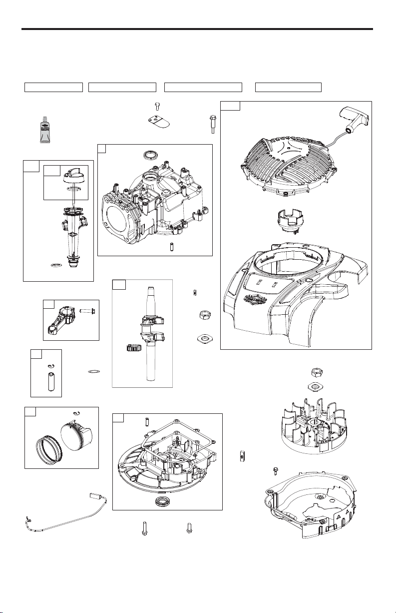
26
MODEL NUMBER 93J02-0098-F1
BRIGGS & STRATTON 4-CYCLE ENGINE
24
26
718
27
1
3
25
28
16
20
12
4
1264
1263
22
718
22A
741
32
29
27
850
598
332
668
48
133013291036
524
842
847
523
356
60
770
58
23
455
332
668
78
37
24
608
304
305
7
TO ASSEMBLE GRASS CATCH ER
1. Put grass catcher frame into grass bag
with rigid part of bag on the bottom.
Make sure the frame handle is outside
of the bag top.
2. Slip vinyl bindings over frame.
NOTE: If vinyl bindings are too stiff, hold
them in warm water for a few minutes. If
bag gets wet, let it dry before using.
Frame
opening
Vinyl
bindings
Frame
handle
INSTALL STARTER ROPE
1. Loosen T-knob.
2. Hold control bar against upper handle.
3. Slowly pull engine starter rope out until
rope will slip into loop of rope guide.
4. Tighten T-knob.
Upper handle
Control bar
Engine
starter rope
Rope guide
T-Knob
TO INSTALL ATTACHMENTS
Your lawn mower was shipped ready to
be used as a mulcher. To convert mower
to bagging or discharging, see “TO CON-
VERT MOWER” in the Operation section
of this manual.

6
Read these instructions and this manual
in its entirety before you attempt to as-
semble or operate your new lawn mower.
IMPORTANT: This lawn mower is shipped
WITHOUT OIL OR GASOLINE in the
engine.
Your new lawn mower has been as sem bled
at the factory with the exception of those
parts left unassembled for shipping pur-
pos es. To ensure safe and proper op er a tion
of your lawn mower, all parts and hard ware
you assemble must be tight ened securely.
Use the correct tools as nec es sary to en-
sure proper tightness. All parts such as
nuts, wash ers, bolts, etc., nec es sary to
complete the as sem bly have been placed
in the parts bag.
TO REMOVE MOWER FROM
CARTON
1. Remove loose parts included with
mower.
2. Cut down two end corners of carton
and lay end panel down flat.
3. Remove all packing materials except
padding be tween upper and lower
handle and padding holding operator
presence control bar to upper handle.
4. Roll lawn mower out of carton and
check carton thor ough ly for additional
loose parts.
ASSEMBLY / PRE-OPERATION
Handle
bracket
Knob
Bolt
MOWING
POSITION
Lower handle
LIFT
UP
Operator
presence
control bar
Upper
handle
LIFT
UP
Handle
knob
HOW TO SET UP YOUR MOW ER
TO UNFOLD HANDLE
IMPORTANT: Unfold handle carefully so
as not to pinch or damage con trol cables.
1. Raise handles until lower handle sec-
tion locks into place in mowing posi-
tion.
2. Remove protective padding, raise up-
per handle sec tion into place on lower
handle and tighten both handle knobs.
3. Remove handle padding holding
operator pres ence control bar to upper
handle.
Your lawn mower handle can be adjusted
for your mowing comfort. Refer to “AD-
JUST HANDLE” in the Service and Adjust-
ments section of this manual.
27
MODEL NUMBER 93J02-0098-F1
BRIGGS & STRATTON 4-CYCLE ENGINE
163
125
133
975
1127
617
104
217
623
724
117
118
623
493
1238
951
122
216
601
187
957
972
318
105
729
137
300
613
836
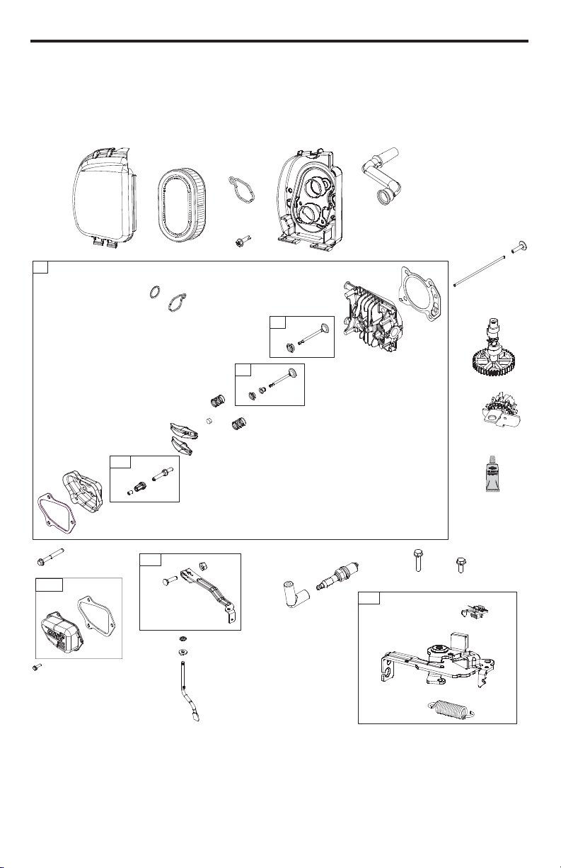
28
MODEL NUMBER 93J02-0098-F1
BRIGGS & STRATTON 4-CYCLE ENGINE
13
1026
1029
45
238
36
35
155
33
34
40
5
868
1029A
192
40
163
623
1022
914
1022
1023
7
830
850
337
635
445
875
968
11
971
163
505
616
562
615
227
404
46
43
745
745A
621
922
923
5
LIST OF APPLICABLE WARRANTY PERIODS: The following list contains the applicable
Warranty Period for your Craftsman product and is based on a combination of the type
of product or component and the intended and actual use of the product or component:
1. 90 DAYS: Craftsman products intended for use or actually used for commercial,
institutional, professional or income-producing purposes
2. 2 YEARS: Craftsman riding lawn mowers, yard and garden tractors, walk behind
mowers, tillers, brush cutters, snow blowers, handheld blowers, backpack blowers,
hedge trimmers and electrical products for noncommercial, nonprofessional, non-
institutional, or non-income-producing use, except for those components which are
part of engine systems manufactured by third party engine manufacturers for which
the purchase has received an separate warranty with product information supplied
at the time of purchase.
3. 1 YEAR: Craftsman power cutters, stump grinders, pole pruners, gas chain saws,
electric chain saws, trimmer attachments, baggers and pole saws for noncommercial,
nonprofessional, non-institutional, or non-income-producing use.
4. 90 DAYS: All defective batteries, which will be replaced during this 90-day Warranty
Period.
5. 60 DAYS: Additional Warranty Period of 60 days will apply to adjustments and worn
products or components BUT DOES NOT INCLUDE WEAR OR ADJUSTMENTS
for products used for commercial, institutional, professional or income-producing
purposes. Wear items include but are not limited to: belts, blades, tires, spark plugs,
air filters, chains, shear bolts, skid plates, scraper bars, drift cutters, ropes, tines,
collection bags and pulleys.
As the Warranty Period runs from the date of purchase and NOT from the date that a
product is delivered, opened, assembled or first used, plea se ensure during this time
period that your product or component has been assembled and tested for correction
operation regardless of when you intend to actually use it. Claims made after the
Warranty Period has expired will not be honored.
PROOF OF PURCHASE/DOCUMENTATION: Warranty coverage is conditioned upon
the original purchaser furnishing Sears Canada or its authorized third party service
provider if applicable, with the original sales receipt or other adequate written proof
of the original purchase date and identification of the product. In the event that the
original purchaser is unable to provide a company of the original sales receipt, Sears
Canada Inc. reserves the right to determine in its sole discretion what other written
proof of the original purchase date and identification of the product is acceptable.
WARRANTY
Serial Number:
Date of Purchase:
Gasoline Capacity / Type: 0,75 Litres (Unleaded Regular)
Oil Capacity: 0,42 Litres
Oil Type (API SJ–SN): SAE 30 (above 0°C/32°F); SAE 5W-30 (below 0°C/32°F)
Spark Plug: Champion RC12YC (Gap: 0,5 mm)
Blade Bolt Torque: 35–40 ft. lbs. (47–54 Nm)
• The model and serial numbers will be found on a decal on the rear of the lawn mower
housing. Record both serial number and date of purchase in space provided above.
PRODUCT SPECIFICATIONS
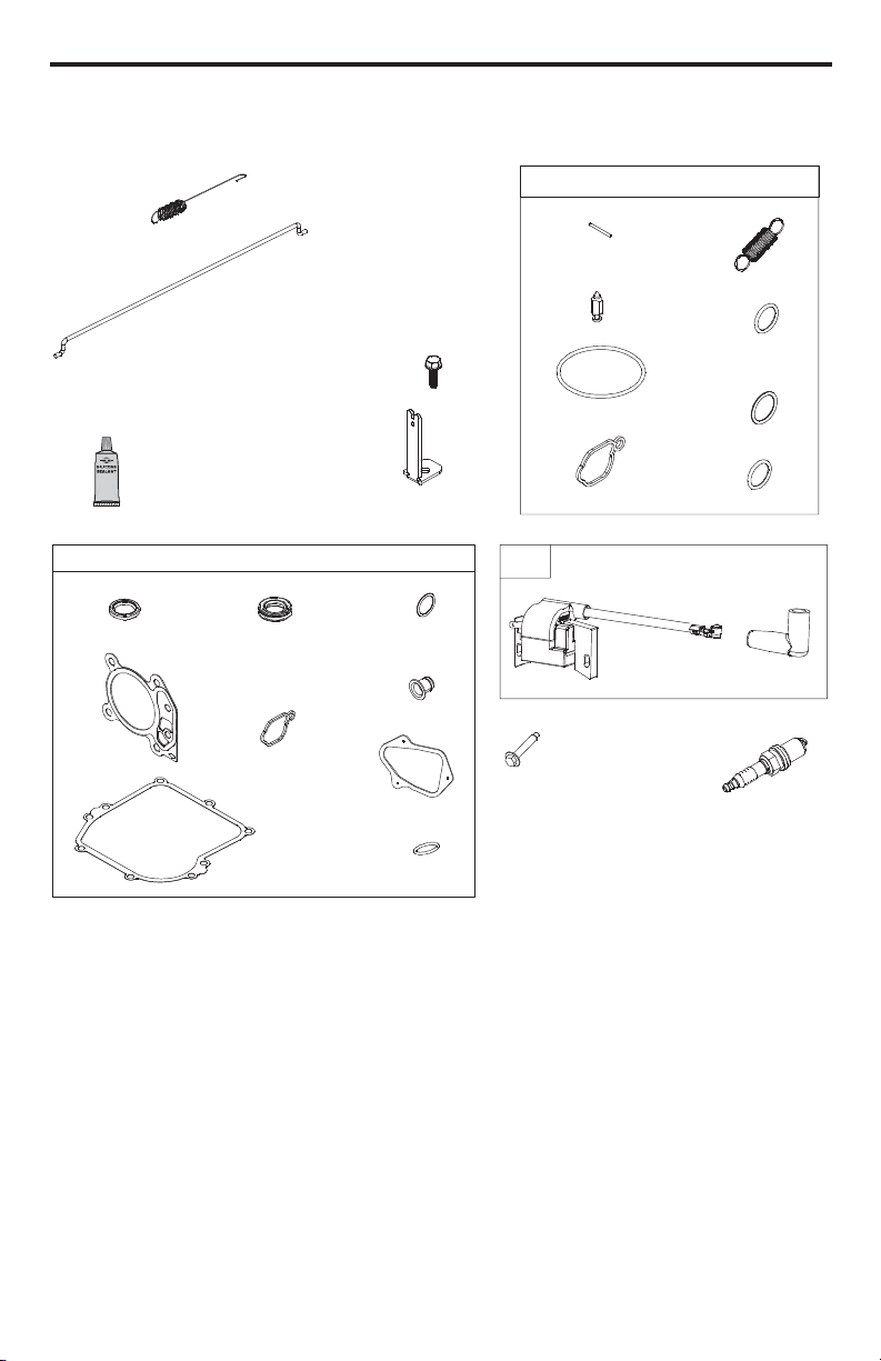
4
WARRANTY
GENERAL: Craftsman products are warranted to be free from defects in materials
or workmanship for a specific time period as set-out below (the “Warranty Period”).
Warranties extend to the original purchaser of a Craftsman product only. Purchases
made through an online auction or through any website other than www.sears.ca are
excluded. The relevant Warranty Period commences on the original date of purchase.
Within this period, Sears Canada, Inc. will, at its sole option, repair or replace any
products or components which fail in normal use. Such repairs or replacement will be
made at no charge to the customer for parts or labor, provided that the customer shall be
responsible for any transportation cost.
EXCLUSIONS: This warranty does not cover failures due to normal wear, abuse, misuse,
neglect (including but not limited to the use of stale fuel, dirt, abrasives, moisture, rust,
corrosion, or any adverse reaction due to improper storage or use habits), improper
maintenance or failure to follow maintenance guidelines and/or instructions, failure to
operate the product in accordance with the owner’s manual or any additional instructions
or information provided at the time of purchase or in subsequent communications with
the original purchaser, accident or unauthorized alterations or repairs made or attempted
by others. Also excluded from warranty coverage – except as provided below - are
the following: maintenance, adjustments, components subject to wear including but
not limited to: cosmetic components, belts, blades, blade adapters, bulbs, tires, filters,
guide bars, lubricants, seats, grips, recoil assy’s, saw chains and bars, trimmer lines and
spools, spark plugs, starter ropers and tines, and discoloration resulting from ultraviolet
light. Any product missing the model and/or serial number identification label will be
disqualified from coverage under this warranty.
REPAIRS: Repairs have a 90 day warranty. If the defective product is still within the
Warranty Period, then the new warranty is 90 days from the date of repair or to the end of
the original Warranty Period, whichever period is longer.
DISCLAIMERS: THE WARRANTIES AND REMEDIES CONTAINED HEREIN ARE
EXCLUSIVE AND IN LIEU OF ALL OTHER WARRANTIES, WHETHER ORAL OR
WRITTEN (OTHER THAN AS STATED HEREIN), AND WHETHER EXPRESS, IMPLIED
OR STATUTORY, INCLUDING BUT NOT LIMITED TO ANY. THIS WARRANTY GIVES YOU
SPECIFIC LEGAL RIGHTS, WHICH MAY VARY FROM PROVINCE TO PROVINCE.
IN NO EVENT SHALL SEARS BE LIABLE FOR ANY INCIDENTAL, SPECIAL, INDIRECT
OR CONSEQUENTIAL DAMAGES, WHETHER RESULTING FROM THE USE, MISUSE
OR INABILITY TO USE THE PRODUCT OR FROM DEFECTS IN THE PRODUCT. THE
EXCLUSIONS IN THIS PARAGRAPH SHALL NOT APPLY IN JURISDICATIONS WHERE
APPLICABLE LAW DOES NOT ALLOW FOR THE EXCLUSION OF INCIDENTAL OR
CONSEQUENTIAL DAMAGES. IN SUCH JURISDICTIONS, THIS PARAGRAPH SHALL
NOT APPLY, BUT THE REMAINING PROVISIONS OF THIS DOCUMENT SHALL REMAIN
VALID.
Sears retains the exclusive right to repair or replace the product or offer a full refund of
the purchase price at its sole discretion. SUCH REMEDY SHALL BE YOUR SOLE AND
EXCLUSIVE REMEDY FOR ANY BREACH OF WARRANTY.
CUSTOMER RESPONSIBILITIES: In additional to complying with all suggested
maintenance guidelines and instructions, customers’ obligations shall include but shall
not be limited to: operating the product in accordance with the owner’s manual or any
additional instructions or information provided at the time of purchase or in subsequent
communications to the purchaser from time to time, exhibit reasonable care in the use,
operation, maintenance, general upkeep and storage of the product. Failure to comply
with these requirements will void any applicable warranty.
29
MODEL NUMBER 93J02-0098-F1
BRIGGS & STRATTON 4-CYCLE ENGINE
Engine Power Rating Information
The gross power rating for individual gas engine models is labeled in accordance with SAE
(Society of Automotive Engineers) code J1940 (Small Engine Power & Torque Rating Procedure),
and rating performance has been obtained and corrected in accordance with SAE J1995 (Revision
2002-05). Torque values are derived at 3060 RPM; horsepower values are derived at 3600 RPM.
Actual gross engine power will be lower and is affected by, among other things, ambient operat-
ing conditions and engine-to-engine variability. Given both the wide array of products on which
engines are placed and the variety of environmental issues applicable to operating the equipment,
the gas engine will not develop the rated gross power when used in a given piece of power equip-
ment (actual “on-site” or net power). This difference is due to a variety of factors including, but not
limited to, accessories (air cleaner, exhaust, charging, cooling, carburetor, fuel pump, etc.), ap-
plication limitations, ambient operating conditions (temperature, humidity, altitude), and engine-to-
engine variability. Due to manufacturing and capacity limitations, Briggs & Stratton may substitute
an engine of higher rated power for this Series engine.
850
7
358
1472
868
163
623
12
3
20
163
121
104
617
623
217
1022
105
137A
1218
202
188
222
209
334
333
337
635

30
KEY PART
NO. NO. DESCRIPTION
1 592359 Cylinder Assembly
3 299819s Kit-Bushing / Seal
(Magneto Side)
4 594101 Sump-Engine
5 592641 Head-Cylinder
7 592358 Gasket-Cylinder Head
11 590522 Tube-Breather
12 799587 Gasket-Crankcase
13 590512 Screw (Cylinder Head)
16 595024 Crankshaft
20 391781s Seal-Oil (PTO Side)
22 692551 Screw (Crankcase Cover /
Sump) (1/4-20 x 1.1)
22A 590763 Screw (Crankcase Cover /
Sump) (1/4-20 x .78)
23 590544 Flywheel
24 222698s Key-Flywheel (Aluminum)
25 592360 Piston Assembly (Standard)
26 592660 Ring Set (Standard)
27 691588 Lock-Piston Pin
28 298909 Pin-Piston (Used After
Date Code 15100100)
699659 Pin-Piston Pin (Used Before
Date Code 15100200)
29 594089 Rod-Connecting (Used After
Date Code 15100100)
590518 Rod-Connecting (Used
Before Date Code 15100200)
32 691664 Screw (Connecting Rod)
33 590531 Valve-Exhaust
34 590530 Valve-Intake
35 590532 Spring-Valve (Intake)
36 590532 Spring-Valve (Exhaust)
37 594729 Guard-Flywheel
40 590528 Retainer-Valve
43 697799 Slinger-Governor/Oil
45 590514 Tappet-Valve
46 592968 Camshaft
48 N/A Short Block
KEY PART
NO. NO. DESCRIPTION
58 591108 Rope-Starter
60 281434s Grip-Starter Rope
78 793480 Screw (Flywheel Guard)
(M5 x 14mm)
104 590558 Pin-Float Hinge
117 592805 Jet-Main (Standard)
118 592690 Jet-Main (High Altitude)
(5000 > 9000 Feet)
121 590589 Kit-Carburetor Overhaul
122 590549 Spacer-Carburetor
125 592361 Carburetor
133 591120 Float-Carburetor
137 594633 Seal-O Ring (Float Bowl)
137A 593235 Seal-O Ring (Float Bowl)
155 590529 Plate-Cylinder Head
163 799580 Gasket-Air Cleaner
187 791766 Line-Fuel
(Cut To Required Length)
188 793480 Screw (Control Bracket)
(M5 x 14mm)
192 590535 Adjuster-Rocker Arm
202 590517 Link-Mechanical Governor
209 590541 Spring-Governor (Purple)
216 590547 Link-Choke
217 590740 Spring-Choke Return
222 590560 Bracket-Control
227 590520 Lever-Governor Control
238 590533 Cap-Valve
300 595516 Muffler
304 593961 Housing-Blower
305 590586 Screw (Blower Housing)
318 793480 Screw (Mounting Bracket)
332 690662 Nut (Flywheel)
333 593872 Armature-Magneto
334 691061 Screw (Magneto Armature)
(#8-32 x .9)
337 591039 Plug-Spark
356 692390 Wire-Stop
358 595350 Gasket Set-Engine
MODEL NUMBER 93J02-0098-F1
BRIGGS & STRATTON 4-CYCLE ENGINE
3
• Do not operate the machine while under
the influence of alcohol or drugs.
• Never operate machine in wet grass.
Always be sure of your footing: keep a
firm hold on the handle; walk, never run.
• Disengage the drive system, if so equipped,
before starting the engine (motor).
• If the equipment should start to vi brate
abnormally, stop the engine (motor) and
check immediately for the cause. Vibra-
tion is generally a warning of trouble.
• Always wear eye protection when op er-
at ing machine.
• Use extra care when approaching blind
corners, shrubs, trees, or other objects
that may obscure vision.
• When loading or unloading this ma-
chine, do not exceed the maximum
recommended operation angle of 15°.
• Wear proper Personal Protective Equip-
ment (PPE) while operating this ma-
chine, including (at a minimum) sturdy
footwear, eye protection, and hearing
protection. Do not mow in shorts or
open toed footwear.
Always let someone know you are outside
mowing.
III. SLOPE OPERATION
Slopes are a major factor related to slip &
fall accidents, which can result in severe
injury. All slopes require extra caution. If
you feel uneasy on a slope, do not mow it.
DO:
• Mow across the face of slopes: nev er
up and down. Exercise extreme caution
when changing direction on slopes.
• Remove obstacles such as rocks, tree
limbs, etc.
• Watch for holes, ruts, bumps or hidden
objects. Uneven terrain could cause a
slip and fall accident. Tall grass can hide
obstacles.
DO NOT:
• Do not mow near drop-offs, ditches or
embankments. You could lose your foot-
ing or balance.
• Do not mow on wet grass or excessively
steep slopes. Poor footing could cause
a slip and fall accident.
IV. SAFE HANDLING OF GASOLINE
To avoid personal injury or property dam-
age, use extreme care in handling gaso-
line. Gasoline is extremely flammable and
the vapors are explosive.
• Extinguish all cigarettes, cigars, pipes
and other sources of ignition.
• Use only an approved container.
• Never remove gas cap or add fuel with
the engine running.
• Allow engine to cool before refueling.
• Never refuel the machine indoors.
• Never store the machine or fuel contain-
er where there is an open flame, spark
or pilot light such as a water heater or
on other appliances.
• Never fill containers inside a vehicle, on
a truck or trailer bed with a plastic liner.
Always place containers on the ground
away from your vehicle before filling.
• Remove gas-powered equipment from
the truck or trailer and refuel it on the
ground. If this is not possible, then
refuel such equipment with a portable
container, rather than from a gasoline
dispenser nozzle.
• Keep the nozzle in contact with the rim
of the fuel tank or container opening at
all times until fueling is complete. Do
not use a nozzle lock-open device.
• If fuel is spilled on clothing, change
clothing immediately.
• Never overfill fuel tank. Replace gas
cap and tighten securely.
V. GENERAL SERVICE
• Never run a machine inside a closed area.
• Never make adjustments or repairs with
the engine (motor) running. Dis con nect the
spark plug wire, and keep the wire away
from the plug to prevent ac ci den tal starting.
• Keep all nuts and bolts tight to be sure the
equipment is in safe working condition.
• Never tamper with safety devices.
Check their proper operation reg u lar ly.
Never do anything to interfere with the
intended function of a safety device or
reduce the protection provided by a
safety device.
• Keep machine free of grass, leaves, or
other debris build-up. Clean oil or fuel spill-
age. Allow machine to cool before storing.
• Stop and inspect the equipment if you
strike an object. Repair, if nec es sary,
before restarting.
• Never attempt to make wheel height
adjustments while the engine is running.
• Grass catcher components are sub ject
to wear, dam age, and de te ri o ra tion,
which could expose moving parts or
allow objects to be thrown. Frequently
check com po nents and replace with
man u fac tur er’s recommended parts,
when necessary.
• Mower blades are sharp and can cut.
Wrap the blade(s) or wear gloves, and
use extra caution when ser vic ing them.
• Do not change the engine governor set-
ting or overspeed the engine.
• Maintain or replace safety and instruc-
tion labels, as necessary.

2
TABLE OF CONTENTS
Safety Rules .......................................... 2-3
Warranty ................................................ 4-5
Product Spec i fi ca tions ........................... 5
Assembly/Pre-Operation ....................... 6-7
Operation ............................................ 8-12
Maintenance Schedule .......................... 13
Maintenance ...................................... 13-16
Service and Adjustments .................. 17-18
Storage .............................................. 18-19
Troubleshooting ................................ 20-21
Repair Parts ....................................... 22-31
Sears Service ...........................Back Cover
IMPORTANT: This cutting machine is
capable of amputating hands and feet and
throwing objects. Failure to observe the
following safety instructions could result in
serious injury or death.
Look for this symbol to point out im por-
tant safety precautions. It means
CAU TION!!! BECOME ALERT!!!
YOUR SAFE TY IS INVOLVED.
WARNING: In order to prevent ac ci-
den tal starting when setting up, trans port-
ing, ad just ing or making repairs, always
dis con nect spark plug wire and place wire
where it can not come in contact with plug.
CAUTION: Muffler and other engine
parts become extremely
hot during operation and
remain hot after engine
has stopped. To avoid
severe burns on contact,
stay away from these areas.
I. CHILDREN
WARNING: CHILDREN CAN
BE SERIOUSLY INJURED OR
KILLED BY THIS EQUIPMENT.
Carefully read and follow all of
the safety instructions below.
The American Academy of Pediatrics
recommends that children be a minimum
of 12 year of age before operating a
pedestrian controlled lawn mower and a
minimum of 16 years of age before operat-
ing a riding lawn mower.
Tragic accidents can occur if the op er a tor is
not alert to the presence of children. Children
are often attracted to the ma chine and the
mowing activity. Never assume that children
will remain where you last saw them.
• Keep children out of the mowing area
and under the watchful care of a re-
spon si ble adult other than the operator.
• Be alert and turn machine off if chil dren
enter the area.
• Before and while walking back wards,
look behind and down for small chil-
dren.
• Never allow children to operate the
machine.
II. GENERAL OPERATION
• Read, understand, and follow all
in struc tions on the machine and in the
manual(s) before starting. Be thor ough ly
familiar with the controls and the proper
use of the machine before starting.
• Do not put hands or feet near or under
rotating parts. Keep clear of the dis-
charge opening at all times.
• Only allow responsible individuals, who
are familiar with the in struc tions, to
operate the machine.
• Clear the area of objects such as rocks,
toys, wire, bones, sticks, etc., which
could be picked up and thrown by
blade. Stay behind the handle when the
engine (motor) is running.
• Be sure the area is clear of other people
before mowing. Stop ma chine if anyone
enters the area.
• Do not operate machine bare footed or
while wearing sandals. Al ways wear
substantial footwear with good ankle
support while mowing.
• Do not pull mower backwards unless
absolutely nec es sary. Always look down
and behind before and while moving
backwards.
• Never direct discharged material toward
anyone. Avoid discharging material
against a wall or obstruction. Material may
richochet back toward the operator. Stop
blade when crossing gravel surfaces.
• Do not operate the mower without
proper guards, plates, grass catcher or
oth er safety protective devices in place.
• See manufacturer’s instructions for
proper operation and installation of
accessories. Only use accessories ap-
proved by the manufacturer.
• Stop the blade(s) when crossing grav el
drives, walks, or roads.
• Never leave a running machine unattended.
• Stop the engine (motor) and wait until
the blade comes to a complete stop
before clean ing the machine, removing
the grass catcher, or unclogging the
discharge chute.
• Mow only in daylight or good artificial light.
SAFETY RULES
31
MODEL NUMBER 93J02-0098-F1
BRIGGS & STRATTON 4-CYCLE ENGINE
KEY PART
NO. NO. DESCRIPTION
404 690272 Washer (Governor Crank)
445 593260 Filter-Air Cleaner Cartridge
455 593960 Cup-Flywheel
493 593330 Bracket-Mounting
(Carburetor)
505 793515 Nut (Governor Control Lever)
523 796503 Dipstick
524 691876 Seal-Dipstick Tube
562 793514 Bolt
(Governor Control Lever)
598 592587 Shim-End Play (Crankshaft)
(Used After Date Code
15100100)
593291 Shim-End Play (Crankshaft)
(Used Before Date Code
15100200)
601 791850 Clamp-Hose (Green)
608 593959 Starter-Rewind
613 590562 Screw (Muffler)
615 690340 Retainer-Governor Shaft
616 590516 Crank-Governor
617 270344s Seal-O Ring (Intake Manifold)
621 692310 Switch-Stop
623 799581 Seal-O Ring
(Carburetor Spacer)
635 692076 Boot-Spark Plug
668 590546 Spacer (Flywheel)
718 690959 Pin-Locating
724 697478 Retainer-Seal
729 594752 Clip-Wire
741 594105 Gear-Timing
745 691146 Screw (Brake) (#10-32 x .8)
745A 690859 Screw (Brake) (#10-32 x .5)
770 595355 Kit-Rewind/Blower Housing
830 590536 Stud-Rocker Arm
836 690661 Screw (Muffler Guard)
(#8-18 x .4)
842 691031 Seal-O Ring (Dipstick)
847 590572 Dipstick/Tube Assembly
KEY PART
NO. NO. DESCRIPTION
850 100106 Sealant-Silicone
868 590534 Seal-Valve
875 595661 Base-Air Cleaner
914 591103 Screw (Rocker Cover)
922 692135 Spring-Brake
923 691487 Brake
951 591104 Lever-Choke
957 591003 Cap-Fuel
968 595658 Cover-Air Cleaner
971 590552 Screw (Air Cleaner Base
to Carburetor)
972 590568 Fuel-Tank
975 594632 Bowl-Float
1022 595341 Gasket-Rocker Cover
1023 590513 Cover-Rocker
1026 590515 Rod-Push
(Intake and Exhaust)
1029 590526 Arm-Rocker (Exhaust)
1029A 590527 Arm-Rocker (Intake)
1036 - - - Label-Emissions (Available
From A Briggs & Stratton
Authorized Dealer)
1127 590554 Screw (Float Bowl
to Carburetor Body)
1238 590562 Screw (Carburetor Spacer)
(M5 x 17mm)
1263 697124 Reed-Breather
1264 793453 Screw (Breather Reed)
1329 N/A Replacement Engine
1330 N/A Repair Manual
- - 398067 Spark Arrester
(available accessory)
Carburetor Overhaul Kit Key No. 121
Engine Gasket Set Key No. 358
NOTE: All component dimensions given in U.S.
inches. 1 inch = 25.4 mm

587785602 Rev. 2 12.13.16 BY Printed in U.S.A.
Model No.
944.364702
CAUTION:
Read and follow all
Safety Rules and In struc tions
before operating this equipment
Owner’s Manual
ROTARY LAWN MOWER
625 Series Briggs & Stratton Engine
Power-Propelled
22" Multi-Cut
Sears Canada, Inc., Toronto, Ontario M5B 2B8