Loading ...
Loading ...
Loading ...
page 7
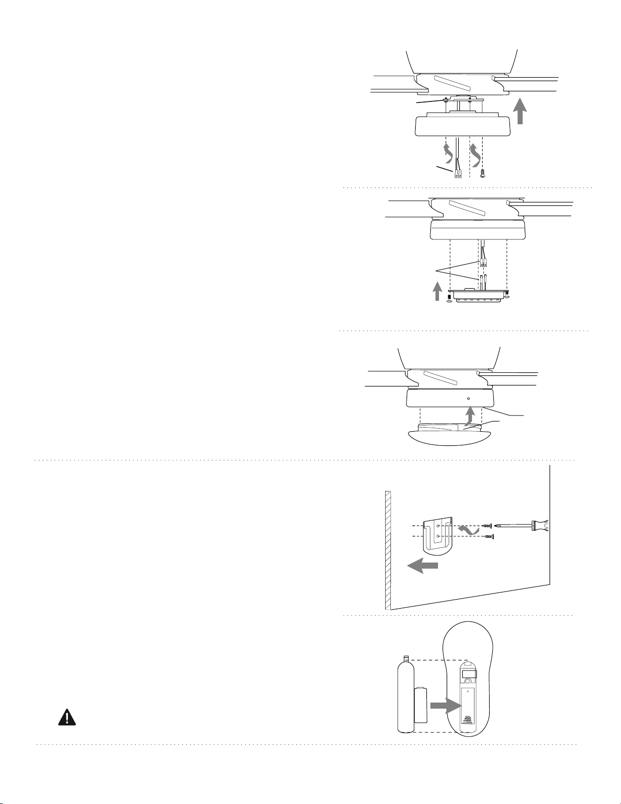
9. Light Kit Assembly.
Remove 1 screw from motor plate on underside
of motor housing and partially loosen the other
2 screws. Align slotted holes in fitter plate with
loosened screws in motor plate, allowing molex
plugs from motor housing to come through
hole in middle of fitter plate. Twist fitter plate to
lock. Re-insert screw that was previously
removed and securely tighten all 3 screws with
a Phillips screwdriver. [Refer to diagram 1.]
Remove 3 screws from underside of fitter plate.
Save for later use.
Connect WHITE wire from LED light kit to
WHITE wire from motor housing. Connect
BLACK wire from LED light kit to BLUE (or
BLACK) wire from motor housing. Be sure that
molex connections snap together completely.
Carefully arrange wiring within the back of
LED light kit.
Align holes in
LED light kit
with
holes in fitter plate. Re-insert screws that were
previously removed and tighten all 3 screws
securely. [Refer to diagram 2.]
Locate slots on glass shade and align with
nodules on inside of fitter plate. Gently push up
on glass shade and turn to the RIGHT
(clockwise) until it slides completely into place.
[Refer to diagram 3.] Note: Pull down VERY
GENTLY on glass shade to make sure that glass
shade is secure.
(back side)
Battery Cover
Remote Control
Transmitter
Battery
10. Remote Control Operation.
If you wish to use the remote control bracket, install
screws, included in remote pack, through bracket and
into the desired installation site. The remote control
transmitter rests inside the bracket.
CAUTION: The remote control transmitter can be
programmed to multiple receivers or fans. If this is not
desired, turn wall switch off to any other programmable
receiver or fan.
Remove battery cover from back of remote control
transmitter. Install battery (included) with positive (+)
end toward top of remote control transmitter. Replace
battery cover.
["Remote Control Operation" continued on next
page.]
WARNING: Choking Hazard - Small parts.
Keep battery away from children.
Remote Control
Bracket
Wall
Bracket
Screws
fitter plate
motor housing
molex connections
diagram 1
motor plate
diagram 3
molex connections
diagram 2
fitter plate
LED light kit
fitter plate
motor housing
glass shade
slot
nodule
Loading ...
Loading ...