Loading ...
Loading ...
Loading ...
INSTALLINGTHEFRONTRAIL
See Figures 15, 16, and 17.
• Locate the front rail pieces, the switch assembly,
and the following hardware:
6 square head bolts (5/16-18 x 3/4 in.)
6 flat washers (5/16 in.)
6 hex nuts (5/16-18)
Front rail connector
Right and left end caps for front rail
2 screws (#8-32 x 1/2 in.) for end caps
• Set aside the end caps and two screws until the rip
fence and front rail have been aligned and the
switch has been installed.
[] Insert the six square head bolts into table and
extensions, so the bolt heads extend out 1/2 in.
• Loosely attach a flat washer and a hex nut to each
bolt. See Figure 15.
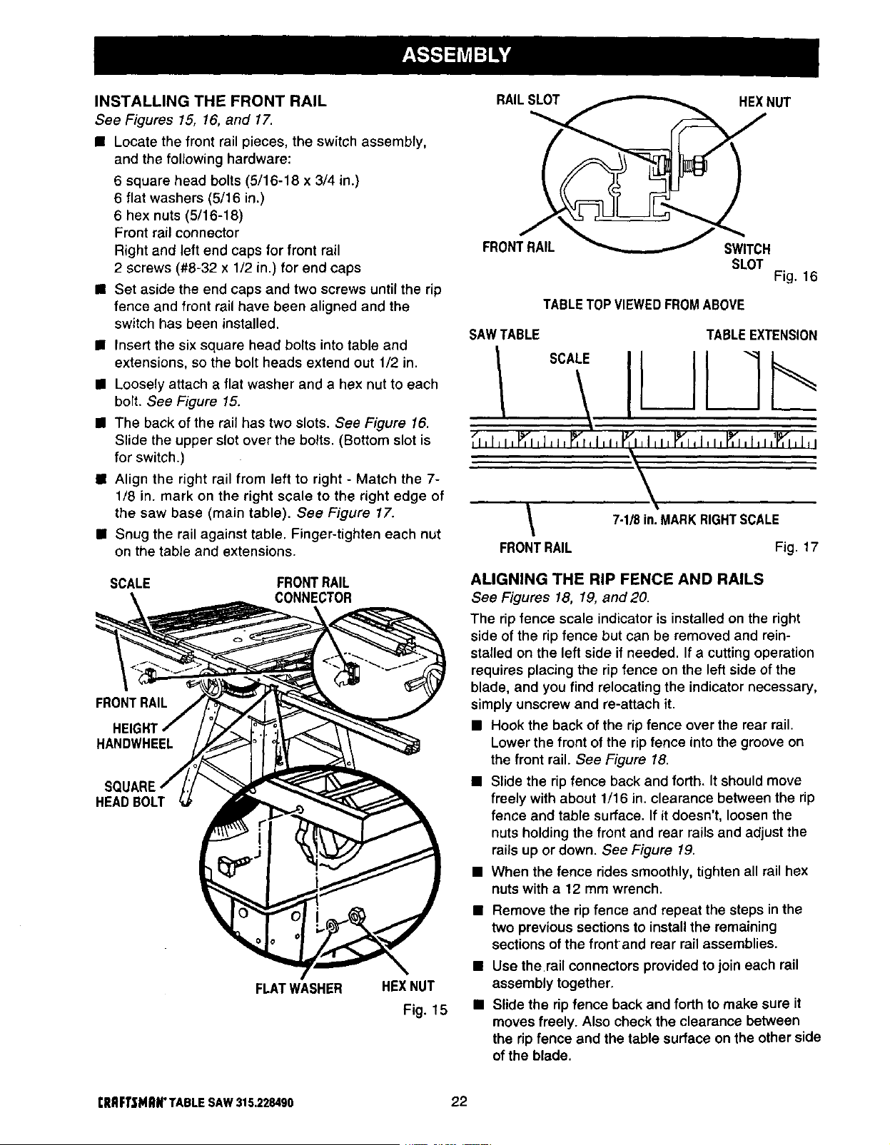
• The back of the rail has two slots. See Figure 16.
Slide the upper slot over the bolts. (Bottom slot is
for switch.)
• Align the right rail from left to right - Match the 7-
1/8 in. mark on the right scale to the right edge of
the saw base (main table). See Figure 17.
• Snug the rail against table. Finger-tighten each nut
on the table and extensions.
SCALE FRONTRAIL
CONNECTOR
FRONTRAIL
HEIG
HANDWHEEL
HEADBOLT
FLATWASHER HEXNUT
Fig. 15
RAILSLOT
HEXNUT
FRONTRAIL
SWITCH
SLOT
Fig. 16
TABLETOPVIEWEDFROMABOVE
ALIGNING THE RIP FENCE AND RAILS
See Figures 18, 19, and20
The ripfence scale indicator is installed on the right
side of the ripfence but can be removed and rein-
stalled on the left side if needed, If a cutting operation
requires placing the ripfence on the left side of the
blade, and you find relocating the indicator necessary,
simply unscrew and re-attach it.
• Hook the back of the ripfence over the rear rail
Lower the front of the ripfence into the groove on
the front rail. See Figure 18
• Slide the ripfence back and forth. It should move
freely with about 1/16 in clearance between the rip
fence and table surface If itdoesn't, loosen the
nuts holding the front and rear railsand adjust the
rails up or down. See Figure 19,
• When the fence rides smoothly, tighten all rail hex
nuts with a 12 mm wrench.
• Remove the rip fence and repeat the steps inthe
two previous sections to install the remaining
sections of the frontand rear rail assemblies.
• Use the rail connectors provided tojoin each rail
assembly together,
• Slide the rip fence back and forth to make sure it
moves freely. Also check the clearance between
the ripfence and the table surface on the other side
of the blade.
I:RRFI'SMNN"TABLESAW315.228490 22
Loading ...
Loading ...
Loading ...