Loading ...
Loading ...
Loading ...
Q
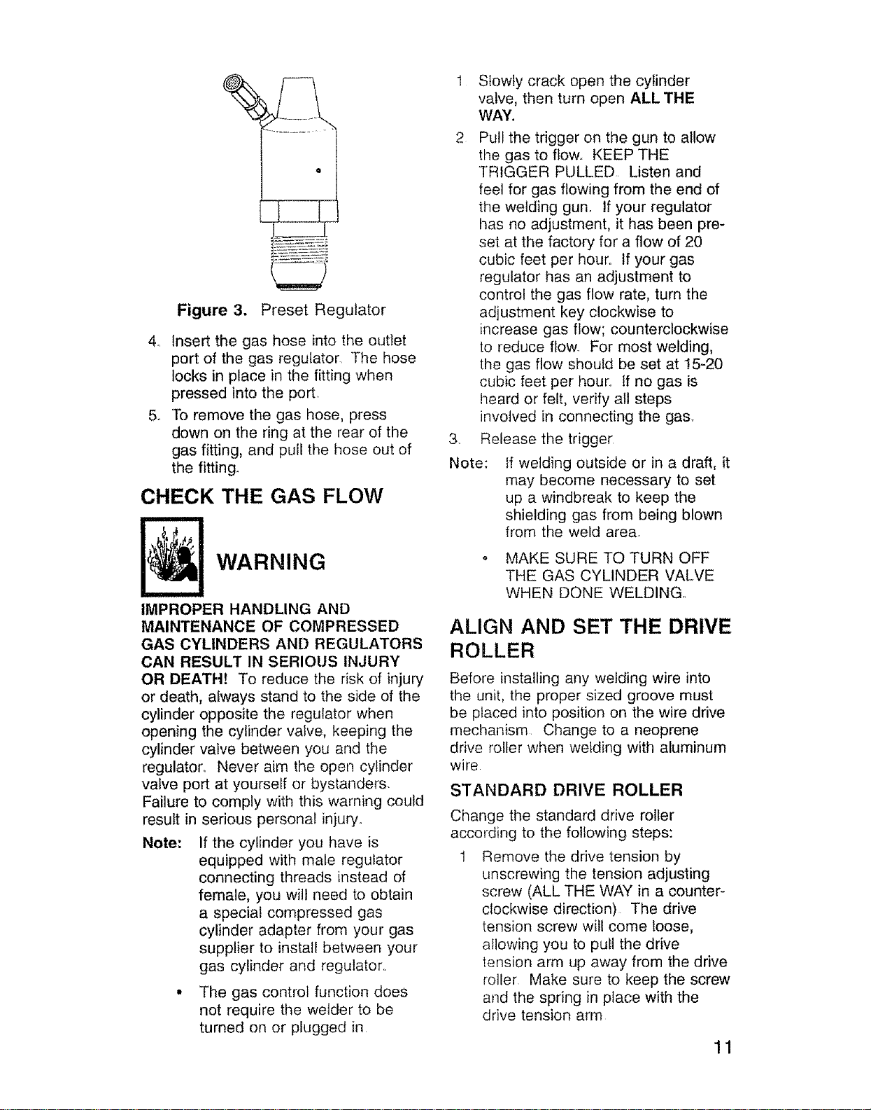
Figure 3. Preset Regulator
4. Insert the gas hose into the outlet
port of the gas regulator The hose
locks in place in the fitting when
pressed into the port
5. To remove the gas hose, press
down on the ring at the rear of the
gas fitting, and pull the hose out of
the fitting.
CHECK THE GAS FLOW
WARNING
IMPROPER HANDLING AND
MAINTENANCE OF COMPRESSED
GAS CYLINDERS AND REGULATORS
CAN RESULT IN SERIOUS INJURY
OR DEATH! To reduce tile risk of injury
or death, always stand to the side of the
cylinder opposite the regulator when
opening the cylinder valve, keeping the
cylinder valve between you and the
regulaton Never aim the open cylinder
valve port at yourself or bystanders.
Failure to comply with this warning could
result in serious personal injury.
Note: If the cylinder you have is
equipped with male regulator
connecting threads hqstead of
female, you will need to obtain
a special compressed gas
cylinder adapter from your gas
supplier to install between your
gas cylinder and regulator,,
• The gas control function does
not require the welder to be
turned on or plugged in
Note:
Slowly crack open the cylinder
valve, then turn open ALL THE
WAY.
Pull the trigger on the gun to allow
the gas to flow.. KEEP THE
TRIGGER PULLED. Listen and
feel for gas flowing from the end of
the welding gun. If your regulator
has no adjustment, it has been pre-
set at the factory for a flow of 20
cubic feet per hour° If your gas
regulator has an adjustment to
control the gas flow rate, turn the
adjustment key clockwise to
increase gas flow; counterclockwise
to reduce flow_ For most welding,
the gas flow should be set at 15-20
cubic feet per hour.. If no gas is
heard or felt, verify all steps
involved in connecting the ga&
Refease the trigger
If welding outside or in a draft, it
may become necessary to set
up a windbreak to keep the
shielding gas from being blown
from the weld area°
MAKE SURE TO TURN OFF
THE GAS CYLINDER VALVE
WHEN DONE WELDING,,
ALIGN AND SET THE DRIVE
ROLLER
Before installing any welding wire into
the unit, the proper sized groove must
be placed into position on the wire drive
mechanism Change to a neoprene
drive roller when welding with aluminum
wire
STANDARD DRIVE ROLLER
Change the standard drive roller
according to the following steps:
1 Remove the drive tension by
unscrewing the tension adjusting
screw (ALL THE WAY in a counter-
clockwise direction) The drive
tension screw will come loose,
allowing you to pull the drive
tension arm up away from the drive
roller Make sure to keep the screw
and the spring in place with the
drive tension arm
11
Loading ...
Loading ...
Loading ...