Loading ...
Loading ...
Loading ...
DXS-3610 Series Layer 3 Stackable 10GbE Managed Switch Hardware Installation Guide
5
Phase LED(s) Behavior
Phase 1 Locator Lights solid blue during this phase.
Power Remains off during this phase.
Status Remains off during this phase.
Fan Remains off during this phase.
Port Link/Act Remains off during this phase.
Phase 2 Locator Turns off during this phase.
Power Remains off during this phase.
Status Remains off during this phase.
Fan Remains off during this phase.
Port Link/Act Remains off during this phase.
Phase 3 Locator Lights solid green during this phase.
Power Lights solid green during this phase.
Status Blinks green during this phase.
Fan Lights solid green during this phase.
Port Link/Act Lights solid amber during this phase.
System Ready All Return to normal operation behavior.
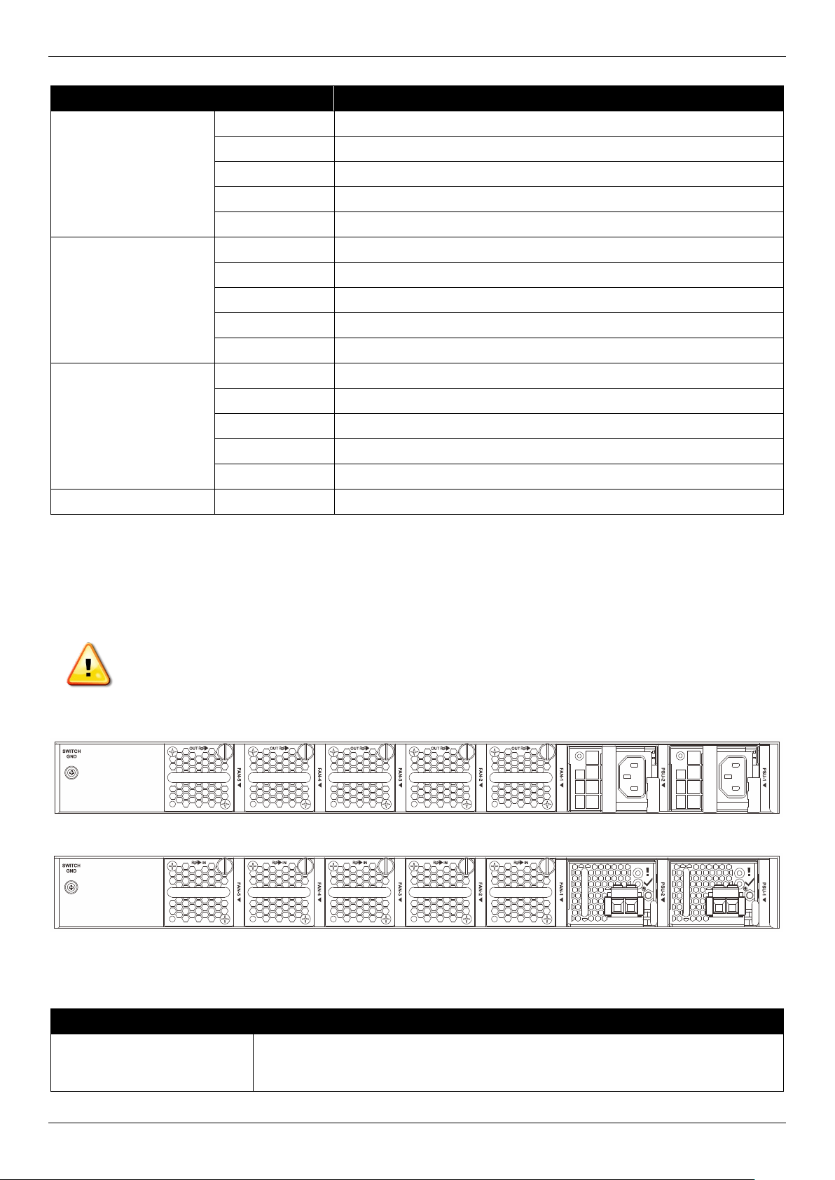
Rear Panel Components
The rear panel features components like LED indicators, PSU (Power Supply Unit) modules, fan modules, and an
electrical grounding point. These components are described in detail below.
CAUTION: When two PSU modules are installed, they must be the same type (two ACs or two DC) and
also use the same airflow direction (back-to-front or front-to-back).
ATTENTION : Lorsque deux modules d'alimentation sont installés, ils doivent être du même type (deux
CA ou deux CC) et utiliser le même sens du flux d'air (dos à dos ou face à face).
Figure 2-5 DXS-3610-54T/DXS-3610-54S Rear Panel (AC PSU)
Figure 2-6 DXS-3610-54T/DXS-3610-54S Rear Panel (DC PSU)
This following table lists the rear panel components on the Switch:
Port Description
Switch GND Use an electrical grounding wire and connect one end of the wire to the switch
GND and the other end of the wire to an electrical grounding point most commonly
found on the Switch mounting rack itself.
Loading ...
Loading ...
Loading ...