Loading ...
Loading ...
Loading ...
www.factorybuysdirect.com
9200253-01D
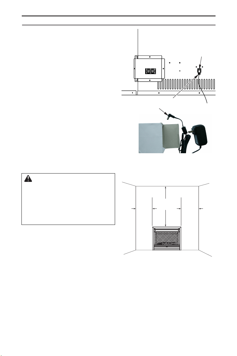
Connector End
of Adapter
Power
Change
Assembly
Back of
Fireplace
Insert
Figure 4 - Connecting to Power Supply
INSTALLATION
CLEARANCES TO COMBUSTIBLES
Figure 5 - Minimum Clearances to Wall
and Ceiling
Ceiling
6"
Min.
6"
Min.
36"
Min.
Side
Wall
Side
Wall
Front View
WARNING: You must main-
tain the minimum clearances
shown in Figure 5. If you can,
provide greater clearances from
oor, ceiling, and joining wall.
Measure from outermost point
of heater.
Minimum Wall and Ceiling
Clearances
A. Clearances from outermost point of heater
to any combustible side wall should not be
less than 6".
B. Clearances from the heater to the ceiling
should not be less than 36".
Note: When heater is installed directly on
carpeting, tile or other combustible material,
other than wood ooring, the heater must be
installed on a metal or wood panel extending
the full width and depth of the heater.
CONNECTING ELECTRICAL
SUPPLY
This replace insert requires an 120V electri-
cal outlet within 4 feet of the unit. There is a
power supply for the remote receiver located
in the bottom of the replace insert. Exten-
sions cords may be used.
The remote receiver requires 4 AA batteries.
This powers the stove in case of an electrical
power outage.
1. Locate 6V DC adapter.
2. Plug connector end of adapter into the
power change assembly on the back of
the replace insert.
3. Plug adapter into a 120V electrical outlet.
Loading ...
Loading ...
Loading ...